
At this stage, you are probably hungry to do some actual UCS server configuration, I am, and this is where it all starts; with policies.
Policies are used to create service profile templates, and from these templates we can assign service profiles to our servers. Before we start though, we should create our UCS organization.
Creating the UCS Organization

A screenshot of create organization window. Values are visible for name and description. O K and the cancel buttons are at the bottom right.
Creating the Organization

A screenshot of create organization pop up. The text in the pop up reads successfully created organization learning U C S. O K button is at the bottom right.
The organization has been completed
You will also notice that the same organization has been created under Service Profiles and also under Service Profile Templates, as well as Pools. You will also find the new organization in the LAN tab, the SAN tab, the Storage tab, and the Chassis tab.
Now, we can start to create our policies. We will not cover every single policy option, as there are a lot of them. Instead, we will focus on the ones required to create a service profile template, which will then be applied to our servers.
Storage Policies

A screenshot of create local disk configuration policy. Values are visible for name, description, and mode and with other selectable option. O K and cancel buttons are at the bottom right.
Local Disk policy
Dynamic vNIC Connection Policies
Dynamic vNICs are not applicable to us (in our sandboxed environment), as these are used for determining connectivity between virtual machines and dynamic vNICs running on servers with VIC adapters. However, if we were running through the service profile wizard (which we will do in the next chapter), this is where we would set up this connectivity. In the same wizard though, is the VLAN creation, which is where we are going to sidestep to.
Creating VLANs

A screenshot of L A N slash LAN cloud. L A N cloud is selected from various options on the left panel. V L A N s tab is selected in the right panel. A pop up window create V L A Ns is in the right panel.
Creating the DB VLAN
As the GUI shows, we can use this to create ranges of VLANs on both fabrics (Common/Global), individual fabrics, or we can configure the fabrics differently. The latter option allows us to specify different VLAN IDs for each fabric (though the name we give this particular VLAN will be the same across both fabrics, just the VLAN ID will be different).
The sharing type is for setting up private VLANs (PVLAN) and allows us, if we should so desire, to isolate ports. We create a primary VLAN and one (or more) secondary VLANs, which can either be an isolated or a community VLAN. Isolated ports can only communicate with the associated port in the primary VLAN, not even with each other. Community ports – communicate with each other and with promiscuous ports. For both Isolated and Community VLANs, we must create a primary VLAN first.

A screenshot of L A N slash L A N cloud. V L A N s tab is selected in the top panel. A table of 7 columns and 9 rows is under a section titled all under the tab.
Our VLANs
vNIC/vHBA Placement
UCS blades have a component called a “Mezzanine” card. Mezzanine cards can give us storage acceleration, port expansion, GPUs (Graphics Processing Units) and VICs (Virtual Interface Cards). We also have mLOMs (modular LAN on Motherboard) cards, which offer VIC expansion.
The UCS, as we spoke about back in Chapter 2, has an IOM and each IOM has a defined internal bandwidth (the bandwidth that goes to the blades). The 2104 has 2x 10GB, the 2204 has 4x 10GB, and the 2208 has 8x 10GB. This means that a blade can get 80Gb-KR bandwidth across a pair of IOMs.
The “KR” in this equation is a data rate specification across a backplane medium (K), using a 64B/66B (R) coding scheme (which is all to do with the electrical encoding at the physical layer) in a single lane configuration. For a deeper dive into this, check out this very good blog post: www.tbijlsma.com/2012/03/how-ucs-achieves-80gbe-of-bandwidth-per-blade/
We can control how each of our vNICs are assigned to these lanes through a “Placement Policy,” allowing us to utilize the hardware capacity to its fullest. Such as all having all vNICs on one card and all vHBAs (virtual Host Bus Adaptors) on another card; this could be due to compatibility reasons, or card speed.

A screenshot of create placement policy window. Values are visible for name, and the virtual slot machine scheme has selectable options. A table of 3 columns and 4 rows is at the bottom.
Placement Policies
All: the vCON (virtual network interface connection) is used for all vNICS and vHBAs that are assigned to it, not assigned to it, or are dynamic.
Assigned only: Only vNICs and vHBAs are assigned to the vCON.
Exclude-Dynamic: The vCON cannot be used for dynamic vNICS or vHBAs.
Exclude-Unassigned: the vCON can only be used for vNICs or vHBAs assigned to it, or dynamic vNICs and vHBAs.
Exclude usNIC: The vCON cannot be used by user-space NICs.
User-space NICs bypass the kernel when sending packets, improving the performance of the software. For a great blog post on actual use-cases, have a read of https://jeremywaldrop.wordpress.com/2010/08/26/cisco-ucs-vnicvhba-placement-policies/
vMedia Policies

A screenshot of create v media policy window. A pop-up window titled create v media mount has editable and selectable options for name, description, device type, protocol, and so on.
A vMedia policy
In the preceding policy, we would be loading a CD ISO image called Linux.iso from https://san.domain.local/ISOs/Linux. Well, depending on our server boot policy, that is.
Server Boot Policies

A screenshot of create boot policy window. Values are visible for name, description, and so on. A table titled boot order displays 2 options at the bottom.
Server Boot Policy
Maintenance Policies

A screenshot of create maintenance policy window. Values are visible for name, description, and so on. O K and cancel buttons are at the bottom right.
Maintenance Policy
Server Pool Policies
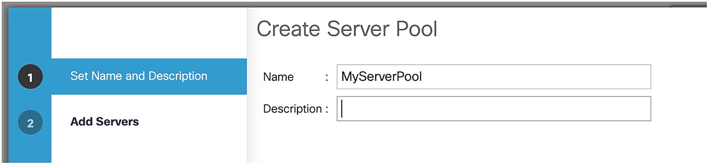
A screenshot of create server pool window. Option 1 set name and description is selected on the left panel. Values are visible only for name and the description box is empty on the right panel.
Creating a server pool
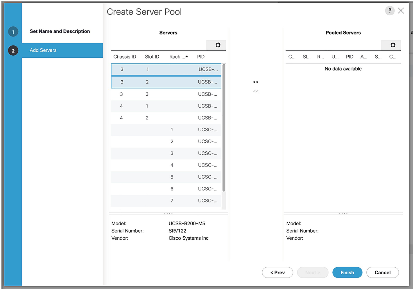
A screenshot of create server pool window. Option 2 add servers is selected on the left panel. Data for servers and pooled servers are on the right panel.
Selecting the servers for the pool

A screenshot of create server pool window. Option 2 add servers is selected on the left panel. Data for servers and pooled servers is visible on the right panel.
Our server pool

A screenshot of create server pool policy qualification window. Values are visible for name and description. No data is available for a section titled qualification.
Server pool policy qualifications

A screenshot of create server P I D qualifications window. U C S B-B 200-M 5 is selected in P I D. O K and cancel buttons are visible at the bottom right.
A server PID qualification
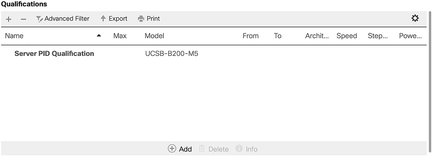
A screenshot of the qualifications section. A table of 9 columns and 1 row. The data in the table are name, server P I D qualification and Model, U C S B-B 200-M 5.
Our completed qualification

A screenshot of create server pool policy window. Values are visible for name, description, and the target pool and qualification have selectable options.
Our Server Pool Policy
The last policies we are going to cover are some small but very important ones!
Operational Policies
Operational policies cover aspects of the servers like BIOS, IPMI, management IP addresses, power control, scrub policies, KVM management and graphics card policies. There are three that we should cover, starting with management IP addresses.
Management IP Addresses

A screenshot of create I P pool window. Option 1 define name and description is selected on the left panel. Values are visible for name, description, and assignment order is set to default.
The KVM pool

A screenshot of create block of I P v 4 addresses window. Values are entered for from, subnet mask, primary D N S, size, default gateway, and secondary D N S.
The KVM Pool IP range

A screenshot of create I P pool window. Option 2 add I P v 4 blocks is selected on the left panel. Data for name, from, to, subnet, default gateway, and so on are on the right panel.
The finished IP pool
As we are not adding an IPv6 pool, click “Next,” and then click “Finish.” Now that we have our port range, we need to specify which port we will be using.
KVM Management Policy
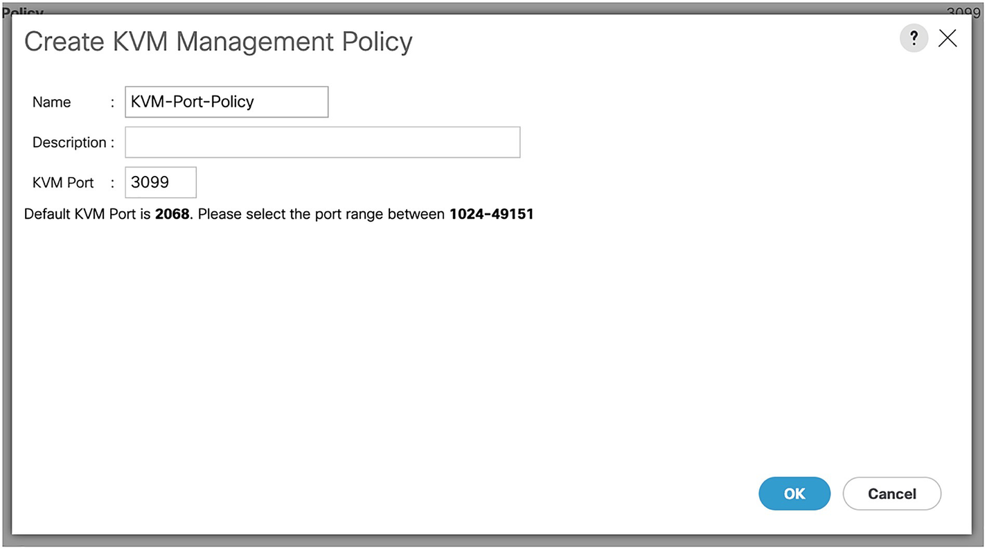
A screenshot of create K V M management policy window. Values are entered for name and K V M port, and the description field is empty. O K and the cancel buttons are at the bottom right.
The KVM management port policy
Onto our final policy.
Scrub Policies
The last set of policies we are going to implement are scrub policies. These control how the disks on a server will be treated in scenarios such as moving blades. For example, you are balancing the blades in your UCS chassis, evening out three application blades across three chassis. You have arranged the downtime, attached the service profile to the empty destination slot, and removed the blade. When you put it in the new chassis slot, the blade is picked up and once it’s booted up, you find that (due to the configured Scrub policy) the disks have been wiped.

A screenshot of create scrub policy window. Value is entered for name, and the description field is empty. No is selected for disk scrub, B I O S setting scrub, flex flash scrub, and persistent memory scrub.
Our scrub policy
Now, we can keep our data safe if we move a blade! Before we move onto the next chapter, however, we need to create a few more items, namely our pools and a VSAN
UUID Pool

A screenshot of create a block of U U I D suffixes window. Values are entered for from and size. The values are from, 0000-000000000001, and size is set to 30. O K and cancel button are at the bottom right.
Creating a UUID Suffix pool
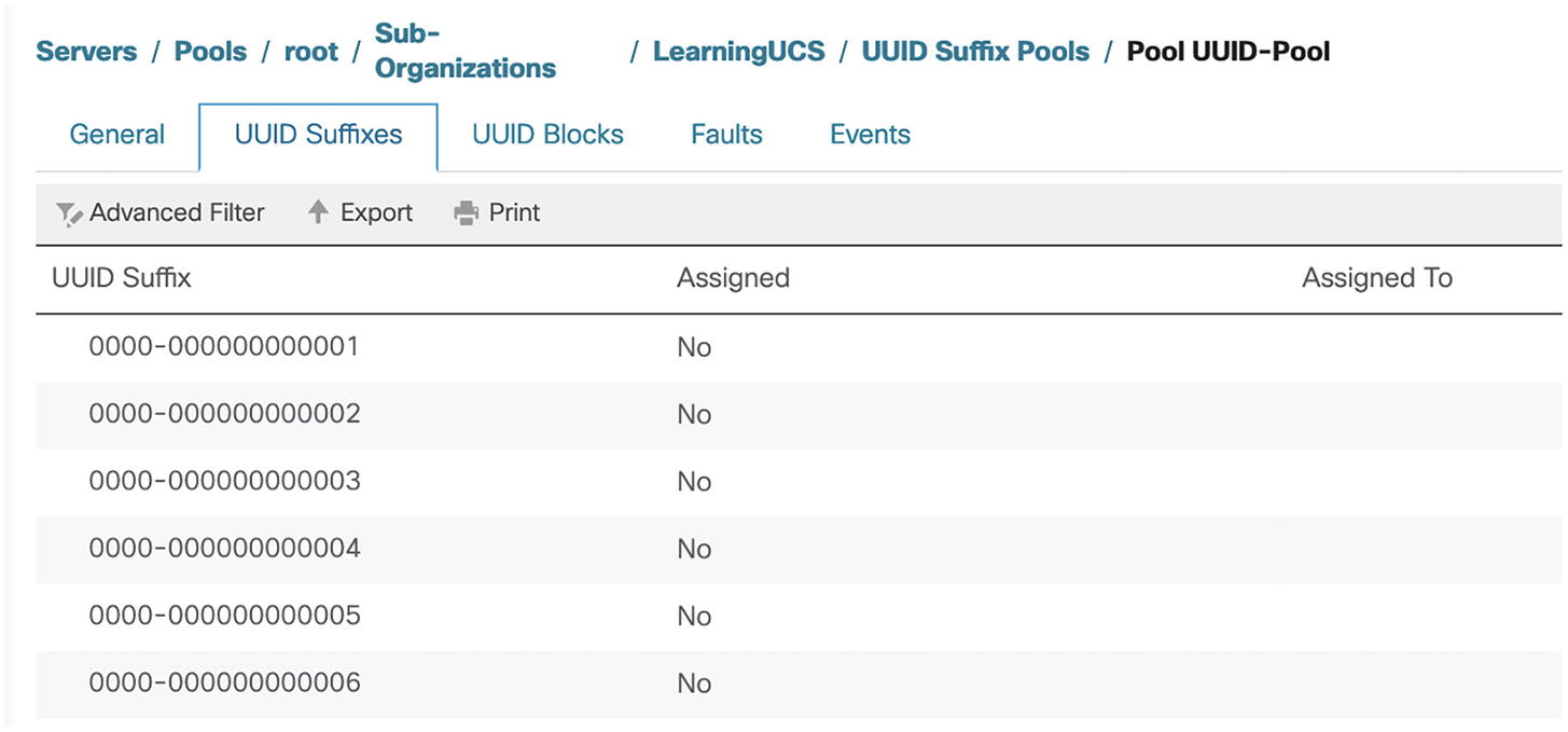
A screenshot of pool U U I D pool. U U I D suffixes tab is selected on the top panel. U U I D suffixes 0000-000000000001, 2, 3, 4, 5, and 6 are not assigned.
Our UUID pool
MAC Pools

A screenshot of create M A C pool. Option 1 define name and description is selected on the left panel. A value is entered for name, the description field is empty, and the assignment order is set to default.
MyMacPool

A screenshot of create M A C pool window. Option 2 add M A C addresses is selected on the left panel. A pop-up window titled create a block of M A C addresses has values for the first M A C address and size.
Our MAC address block
WWNN

A screenshot of create W W N N pool. Option 1 define name and description is selected on the left panel. Value is entered for name, description field is empty, and assignment order is set to default.
Our WWNN pool

A screenshot of create W W N block window. Option 2 W W N blocks is selected on the left panel. A pop-up window titled create a W W N has values for from and size.
Our WWN block
VSAN
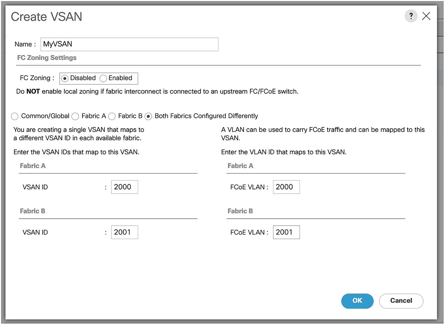
A screenshot of create V S A N window. The screenshot lists various editable fields and selectable options under section F C zoning settings, fabric A, and fabric B.
Our VSAN
Summary
In this chapter, we have created the policies and pools to control our servers. In the next chapter, we will start assigning these to our servers.