
Chapter Three
Structural Infrastructure
Chapter Outline
- Prelude to Chapters 3 through 5
- Introduction
- Foundations
- Skyscrapers
- Schools (ASCE 2009 Grade: D)
- Bridges (ASCE 2009 Grade: C)
- Dams (ASCE 2009 Grade: D)
- Levees and Floodwalls (ASCE 2009 Grade: D–)
- Retaining Walls
- Outro
Learning Objectives
After reading this chapter, you should be able to:
- List the main subsectors and components of the structural sector of the infrastructure.
- Explain the purpose of and list some design criteria for various components of the structural sector.
- Identify various components of the structural sector.
Prelude to Chapters 3 through 5
Chapters 3 through 5 introduce you to the physical portion of the built environment. The broadest categories are termed infrastructure sectors, such as transportation, structural, or environmental. Some sectors are further broken down into subsectors; for example, the transportation sector includes aviation and mass transit. We will also introduce various components, the most fundamental “building blocks” of the sectors. Examples of mass transit components include roadways (with sub-components of pavement, curbs, etc.), buses, rail lines, and trains. Knowledge of these sectors, subsectors, and components is necessary to understand topics presented throughout the remainder of this textbook. In addition to being able to identify components, you will also begin to understand the interrelationships between components, sectors, society, and the environment.

Note that the sectors, subsectors, and components introduced by these chapters are not inclusive (due to the vastness of our infrastructure), nor is our treatment of each exhaustive. In writing these three chapters, we decided to include all sectors or subsectors from the ASCE Report Card for America's Infrastructure, which was introduced in Chapter 1; additional sectors and subsectors are included to demonstrate the variety of infrastructure that exists.
Multi-Disciplinary Aspects of Large Infrastructure Projects
 Hoover Dam Bypass Project
Videos and Animations Demonstrating Construction of Improvements to the Greater New Orleans Hurricane and Storm Damage Risk Reduction System
Additionally, some of the sectors, subsectors, and components are covered in more detail than others. Greater level of detail will be provided for the most common sectors, subsectors, and components (e.g., roads and stormwater management), whereas the less ubiquitous examples (e.g., ports, skyscrapers) are introduced with less detail. This varying level of coverage mirrors that of typical undergraduate civil and environmental engineering programs (e.g., skyscraper and port design are not commonly taught at the undergraduate level). Also, in an attempt to begin to “paint the big picture,” we will briefly discuss design parameters, planning, maintenance, etc., which are topics of more detailed coverage in later chapters.
While reading Chapters 3 through 5, note the interrelationships between sectors and components from each of the chapters; for example, the bridges of this chapter and the roads of Chapter 4, Transportation Infrastructure. Given these interrelationships, categorization of the built environment into three distinct groupings (i.e., structural, transportation, and environmental) is inherently difficult. For example, dams and levees are indeed structures, but have distinct environmental aspects to their design and planning. Likewise the treatment processes at a wastewater treatment facility are designed to protect the environment, but are contained within tanks, reactors, and buildings designed by structural engineers.
Introduction
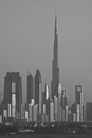
In this chapter, we introduce many types of structures that are part of the built environment. Skyscrapers have long captured the imagination of many young people, inspiring them to become civil engineers. Many of these structures are national or international landmarks (Figure 3.1 and Figure 3.2). However, many additional types of structures exist with the purposes of housing people; storing goods; holding back water; providing places of employment, education, or worship; allowing for the movement of goods and people across water bodies and other obstructions, etc.

Figure 3.1 The Empire State Building (Center) Dominates the Manhattan Skyline. Completed in 1931, this 102-story building was the tallest in the world for four decades. It was named one of the Seven Wonders of the Modern World by the American Society of Civil Engineers (ASCE).
Source: Copyright © oversnap/iStockphoto.

Figure 3.2 Dubai Skyline. The Burj Khalifa, completed in 2010 at a cost of over $1 billion, is the tallest structure in the world at 2,717 feet.
Source: Copyright © Uwe Merkel/iStockphoto.

Foundations
Virtually any structure, be it a building or a bridge, requires a foundation. The foundation may be as simple as a concrete slab, or much more complicated. Foundations are necessary to distribute the weight of the structure onto the soil or rock below it. Without a proper foundation, a structure may sink (settle), tip, crack, or collapse. The strength of the soil or rock below a structure is a critical factor in foundation design. “Weak” soil or rock cannot support much weight. Consequently, the structure's weight must be distributed over a larger area in contact with the soil or rock; this is the fundamental principle behind footings (Figure 3.3).
Figure 3.3 Concrete Footing with Reinforcing Steel (Rebar) for Walls. The footing is approximately three times the width of the wall that will be cast in place later.
Source: M. Penn.
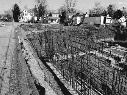
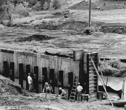
Figure 3.4 Steel Piles for a Bridge Foundation. These steel “H” piles (so named due to the cross-sectional shape) were driven vertically into holes bored into underlying shallow bedrock. Workers are building wooden forms (explained in Chapter 6) around the piles in which concrete will be placed to complete the foundation.
Source: M. Penn.
Very large structures require deep foundations to reach subsoils or rock with greater load bearing capacities. Steel or concrete piles are placed (Figure 3.4), often at great depth, to which the structure is connected. For underwater foundation applications (e.g., bridge piers), temporary watertight structures such as caissons or cofferdams (Figure 3.5) are constructed and pumped dry for subsequent foundation construction work. Accounting for seismic activity from earthquakes is a highly advanced area of study in foundations and structures.
A pile (or piling) is a column placed vertically, deep in the subsurface, as a foundation.
A caisson is a complete enclosure (with a roof) that is pressurized to keep water from entering.
A cofferdam is a walled enclosure (with no “roof”) from which water is removed for construction work within.
Skyscrapers
High-rise structures, while typically privately owned, are of particular importance to infrastructure systems due to the demands created by a large number of people occupying a relatively small footprint; a high-rise condominium may “concentrate” the population equivalent of a small city into the area of a single city block. Needs for water, wastewater, parking, and traffic must be carefully considered when designing these structures and their integration into existing infrastructure systems. The structural design of skyscrapers and the design of the foundations are extremely complex, requiring education beyond a bachelor's degree.
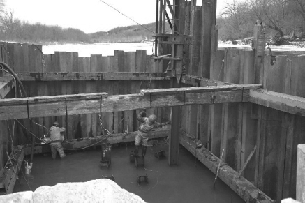
Figure 3.5 Construction Workers Working Inside a Cofferdam.
Source: Courtesy of the Missouri Department of Transportation.
Schools (ASCE 2009 Grade: D)
Schools present challenges beyond structural design because of the many associated infrastructure demands (e.g., transportation, water and wastewater, energy). Collectively, school construction, operation, and maintenance are typically the largest expenses in a community's budget. Schools are often viewed as integral components of neighborhood identity. Rapidly growing regions face great challenges in providing educational facilities to meet growing populations, especially due to the fact that required expenditures are large and long term. Managing this growth can be particularly challenging and requires predictions of future enrollments. Such predictions are made using population growth estimates and the age distribution of the population (i.e., the number of children). If growth is over-predicted, the community will be faced with substantial debt and underutilized facilities. If growth is under-predicted, or if decisions to expand are delayed, facilities will be undersized, resulting in overcrowded and/or substandard temporary classrooms.
Also challenging are schools in large cities where populations are declining (even as neighboring suburbs grow). The existing educational infrastructure was built for and financed by a larger population. Now underutilized, these facilities lead to high costs per student and often to facility closures and mergers. This problem is also common in many rural areas that are experiencing population declines.
Bridges (ASCE 2009 Grade: C)
Bridges are used to span gorges and valleys or to cross any number of obstructions including waterways and other roads. At its simplest, a bridge consists of a deck and its supports. The deck may be used to convey trains, automobiles, pedestrians, or bicyclists. The supports can be as simple as concrete abutments at either end of a span, or as complicated as the towers and cables that support the deck on the Golden Gate Bridge and other suspension bridges.
An abutment is a structure, often of concrete, that supports the ends of a bridge.
As you will learn in Chapter 9, Analysis Fundamentals, the two most fundamental forces on structural members are compression and tension forces. Compression force may be thought of as a “pushing force,” and is the force you feel in your arm as you push on a door to keep the door from opening toward you. Conversely, if you are trying to pull a stuck door open, you are experiencing a pulling or tension force in your arm. The loads acting on a bridge will cause its structural members to experience compression and tension. Considering these forces is a rudimentary first step in analyzing and designing bridges.
The loads on bridges include the traffic (e.g., rail or auto) that will be carried by the bridge. Additionally, the bridge must be able to support its own weight. Other loads may be added by wind or snow. In certain parts of the world, the bridge must also be able to withstand the movements induced by earthquakes.
In designing bridges, engineers have many options at their disposal. That is, there are many ways to transfer the loads from the deck to the earth. Said another way, there are many methods engineers can use to ensure the bridge carries the loads in structural members via tension and compression.
Bridges come in all shapes and sizes: suspension, cable-stayed, steel or concrete arch, trusses, steel girder, or concrete girder (see Figure 3.6). The choice of which type of bridge to use for a given situation depends on:
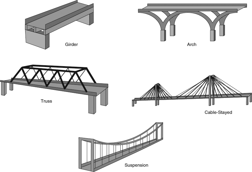
Figure 3.6 Common Bridge Types.
- The distance to be crossed—As the distance increases, additional spans (and therefore additional supports) will be needed; or, if additional supports are not feasible, only certain types of bridges will work (e.g., a suspension bridge).
- The site geology—All loads are transferred from the bridge to the subsurface. The design of the foundations will depend on the strength of the underlying soil or rock.
- The ease by which the entire span length can be constructed—For example, a long water crossing requires much different construction techniques than a short span across a gully.
- The type of traffic, if any, that will pass under the bridge—For example, trucks on freeways, or ships with tall masts on waterways will both affect bridge selection and design.
- The amount of money that project owners are willing to spend—The owners may be willing to spend more money for a bridge that is aesthetically pleasing, or perhaps even more for one that will become a true “symbol” of a city (e.g., Golden Gate Bridge).
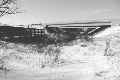
The simplest and most widely used type of bridge is the simple girder or beam bridge (Figure 3.7). Placing a plank or log across a ditch would be the simplest example of a beam bridge. Loads to the parallel beams (Figure 3.8) are transferred to the ends of the beams that rest on abutments. Beam bridges are relatively inexpensive, and their design is relatively straightforward.
Figure 3.7 Examples of Single-Span Bridges. The freeway bridge in the background and the relatively short multi-use trail bridge in the foreground are both simple beam bridges.
Source: P. Parker.
![]() Remember that full-sized versions of textbook photos can be viewed in color at www.wiley.com/college/penn.
Remember that full-sized versions of textbook photos can be viewed in color at www.wiley.com/college/penn.
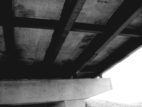
Figure 3.8 Steel I-Beam Girders and Lateral (left to right in photo) Bracing Supporting the Concrete Road Deck of a Girder Bridge.
Source: M. Penn.
Time-Lapse Video of Colorado River Bridge Construction
As the span to cross becomes longer or as the loads become greater, beams and girders become impractical. Early engineers solved this problem with the use of arch bridges; arch bridges are still used worldwide (e.g., see Figure 3.9). In arch bridges, the arches are under compression and transfer loads to the ends of the arches.
“How Stuff Works” Video on Bridge Design
The introduction of steel to bridge building allowed the use of trusses to become widespread. Truss bridges consist of a network of steel members arrayed in triangular shapes. The design of truss bridges is relatively straightforward and therefore can be efficiently and rapidly designed by engineers. Furthermore, they offer exceptional rigidity and relative ease of construction, as compared to the masonry arch bridges that they historically succeeded. They require significant maintenance, as members must be painted regularly to inhibit rust. Although not used widely for highway and railroad use any more, they are regularly found in pedestrian bridges (Figure 3.10). Tension and compression forces for truss bridges will be discussed in Chapter 10, Design Fundamentals.
As spans become longer, piers may be needed (Figure 3.11). However, for crossings with deep or fast-moving water, construction of such supports is impractical. In other cases, additional piers are not desirable as they impede ship traffic. In such cases, a suspension bridge may be most feasible. In a suspension bridge, the loads from the deck are transferred to vertical suspender cables (also termed “hangers”) that in turn are attached to the suspension cables. All cables are under tension, and transfer their loads to the columns (which are under compression) and also to the anchorages on the end. Anchorages are large masses of concrete; in the case of the Golden Gate Bridge, the anchorages each weigh 60,000 tons.
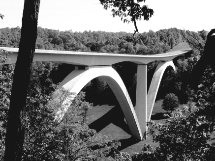
Figure 3.9 Double Arch Bridge on Natchez Trace Parkway (Tennessee).
Source: Courtesy of B. Moore.

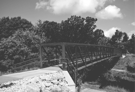
Figure 3.10 Truss Bridge for Pedestrian Use.
Source: Courtesy of A. McNeill.
Cable-stayed bridges are among the most visually striking bridges. Like suspension bridges, the load from the deck is transferred to cables. Unlike suspension bridges, cable-stayed bridges do not have anchorages. That is, all the loads are transferred directly to the towers. Cable-stayed bridges are often stiffer than suspension bridges, and whereas suspension bridges are typically limited to two towers, any number of towers can be incorporated into cable-stayed bridges.
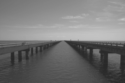
Figure 3.11 Lake Pontchartrain Causeway. At 24 miles long, it is the world's longest bridge over water. The twin, parallel spans are supported by more than 9,500 pilings.
Source: Copyright © Gary Fowler/iStockphoto.

Case in Point: Sunshine Skyway Bridge
In 1980, one of the piers of the Sunshine Skyway Bridge over Tampa Bay was struck by a freighter. A portion of the bridge collapsed, and six vehicles and a bus fell into the water, killing 35 people.
The replacement bridge (Figure 3.12) is a cable-stayed bridge, and is considered to be one of the most beautiful bridges in the United States. It has also become a symbol of Tampa Bay, similar to the way the Gateway Arch has become a symbol of St. Louis or the Golden Gate Bridge a symbol of San Francisco. Notably, the cable-stayed construction for the replacement bridge allows a span length (1,200 feet) that is twice as long as the span opening on the old bridge, which makes it much safer for ship traffic to pass. It also has a larger vertical clearance that can allow taller ships to pass.
The demolition of the old bridge was carried out in dramatic fashion. A video is available on the textbook website.
Video of Demolition of Sunshine Skyway Bridge
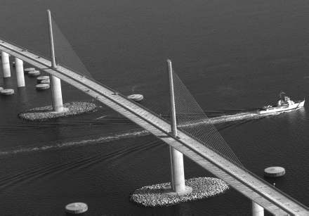
Figure 3.12 The Cable-Stayed Sunshine Skyway Bridge.
Source: Copyright © Tinik/iStockphoto

Dams (ASCE 2009 Grade: D)
There are over 80,000 dams throughout the United States for purposes of navigation (in conjunction with locks), flood control, hydroelectric power, water supply (storage reservoirs), and recreation (boating and fishing).
Dams are primarily earthen (Figure 3.13) or concrete (Figure 3.14). Concrete dams must be designed to resist overturning. For slope stability reasons (i.e., to keep the earthen embankment from moving downward as a mass and thus resulting in dam failure), earthen dams require gentle slopes that necessitate a large footprint (e.g., see Figure 3.13). With a 4:1 (horizontal-to-vertical) slope on both upstream and downstream sides, a 100-foot-high dam would be 800 feet wide at the base.
Figure 3.13 The Fort Peck Dam on the Missouri River in Montana. One of the largest in the United States, this dam is 4 miles long and 250 feet high.
Source: U.S. Army Corps of Engineers/R. Etzel.
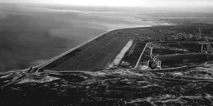

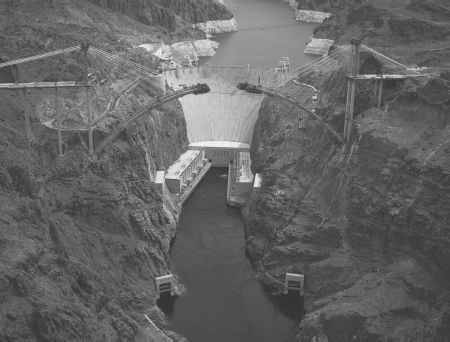
Figure 3.14 The Hoover Dam. Perhaps the most famous dam in the United States, the Hoover Dam was constructed from 1931 to 1936 on the Colorado River at the border of Nevada and Arizona. It is 1,244 feet long and 726 feet tall. In the foreground is the Colorado River Bridge under construction, which was completed in 2010.
Source: Federal Highway Administration.

Major dams are defined as being at least 50 feet in height with a storage capacity of at least 5,000 acre-feet, or of any height with a storage capacity of 25,000 acre-feet or more. As the height of a dam increases, so does the water storage capacity, the potential energy for hydroelectric power, and the extent of property and lives to be affected in the event of a failure.
One acre-foot is the volume of water that occupies an area of 1 acre at a depth of 1 foot and is equivalent to 325,851 gallons or 43,560 ft3.
River flows vary greatly with rainfall intensity and snowmelt. Earthen dams are protected from overtopping (and potential scour and failure) by emergency spillways. Spillways convey flow through an engineered channel, and act as a bypass of the dam during exceedingly high water elevations (Figure 3.15).
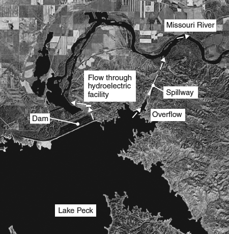
Figure 3.15 Emergency Spillway at the Fort Peck Dam. Routes for normal flow through the hydroelectric facility and emergency flow via the spillway are shown.
Source: Copyright © 2010 TerraMetrics, Inc.
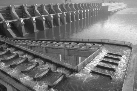
Figure 3.16 A Fish Ladder in Washington.
Source: U.S. Army Corps of Engineers.
Dams for drinking water supply require water intakes. Newer designs incorporate intakes at several water depths to allow water supply managers to select the withdrawal depth based on water quality that varies seasonally and with depth in reservoirs.
The many potential benefits of dams are countered by adverse environmental and social effects that will be discussed later in this book. When fish migration in a river is necessary for ecological reasons, fish ladders, or in extreme cases, fish elevators, are used to allow passage around a dam (Figure 3.16). Many dams are being removed to restore rivers to their free-flowing nature.
Many dams in the United States are in deficient condition. The Association of State Dam Safety Officials estimates that there are over 1,700 high-hazard potential dams (where loss of human life is probable as a result of dam failure) that need repair—more than 1 out of every 10 (ASDSO, 2007). This number has steadily increased (from approximately 400 needing repair in 2001) as a result of insufficient funds and increased development downstream of dams, which increases the number of high-hazard potential dams. The 2009 Report Card for America's Infrastructure states: “In order to make significant improvements in the nation's dams—a matter of critical importance to public health, safety and welfare—Congress, the administration, state dam safety programs, and dam owners will have to develop an effective inspection, enforcement and funding strategy to reverse the trend of increasingly deteriorating dam infrastructure.”
Levees and Floodwalls (ASCE 2009 Grade: D–)
Levees and floodwalls are a means of flood protection that are now in the national spotlight after the Hurricane Katrina disaster in New Orleans (which will be discussed in great detail throughout this book). Levees (earthen embankments sometimes referred to as dikes, Figure 3.17) and floodwalls (typically made of concrete, Figure 3.18) are commonly aligned parallel to rivers. When access through a floodwall is needed during normal (non-flood) river stages, floodgates are installed (Figure 3.19). These gates are closed during high water events.
When designing a levee, the elevation of the top of the levee is determined based on probabilities of stage (for river flooding) or storm surge water elevation (in the case of hurricanes). As the levee height increases, the risk of overtopping and flooding decreases. In emergency situations, elevations may be temporarily raised by the addition of sandbags (Figure 3.20). Permanent increase in elevations can be accomplished by placing a floodwall on top of an existing levee (Figure 3.21). This increased protection from hazard requires additional expenditures since the design, construction, and maintenance costs increase with levee elevation.
Stage refers to the water surface elevation.
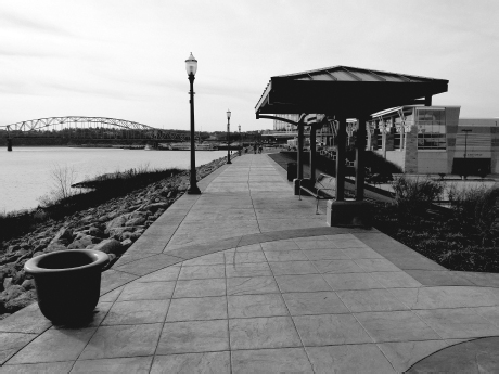
Figure 3.17 An Earthen Levee Along the Mississippi River in Dubuque, Iowa. Note that the levee serves as an attractive pedestrian walkway. The top of the levee is approximately 20 feet above the river level in the photo. The parking lot and ground floor of the hotel in the background are approximately 15 feet below the top of the levee. Note that the river side of the levee is armored with large rip-rap to prevent erosion.
Source: M. Penn.

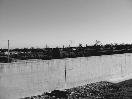
Figure 3.18 A Newly Constructed Portion of the Breached Floodwall during Hurricane Katrina in the Devastated Lower 9th Ward of New Orleans.
Source: M. Penn.

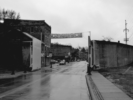
Figure 3.19 Floodgate in a Floodwall Protecting Historic Downtown Galena, Illinois. In the absence of the floodwall and gate, when 14 inches of rain fell in three days in August 2010, the city would have been under 7 feet of water from the adjacent Galena River.
Source: M. Penn.


Figure 3.20 Sandbag Placement Atop a Levee.
Source: City of Anderson, Indiana Emergency Management.
The elevation of the top of a levee is typically based on “100-year” protection, which corresponds to a water elevation with a 1 in 100 (1 percent) chance of occurring in any given year. Currently, there is national debate as to what level of protection should be provided. In the Netherlands, for example, protection is provided at the 2,500-year level (0.04 percent probability) or greater.
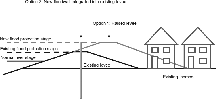
Figure 3.21 A Comparison of the Footprint of a Replacement Levee of Higher Elevation (Option 1) Versus a Floodwall Extension to an Existing Levee (Option 2). A larger footprint (i.e., a wider base) is required for a taller levee because the side slope is a fixed design parameter. To accommodate this larger footprint, existing homes would need to be removed or relocated. Adding a floodwall to an existing levee can raise the flood protection elevation without increasing the required footprint.
Source: Figure modified with permission from ASCE, 2007.
Levees are owned and maintained by various levels of government, from local to national. Largely for this reason, there is no accurate estimate of the total length of levees in the United States. Many levees were designed and constructed several decades ago, and are considered deficient as a result of poor maintenance, differential settling, outdated designs, or improper construction.
Levee Risk
The following predictions have been provided by the U.S. Army Corps of Engineers—Louisville District regarding the deficient levee that protects the city of Anderson, Indiana:
- Within next 10 years—67 percent chance of levee failure
- Within next 20 years—94 percent chance of levee failure
- Within next 50 years—100 percent chance of levee failure
In this case, note that “failure” is not referring to “failure to provide flood protection” (e.g., being overtopped by flood waters), but to true structural failure of the levee (e.g., breaching).
Levees and floodwalls should be a primary, but not the sole, means of protection. A multiple lines of defense strategy toward flood risk minimization has been adopted by the U.S. Army Corps of Engineers for coastal Louisiana:
“No single measure or approach for achieving risk reduction will be sufficient for achieving the multiple risk reduction objectives established for coastal Louisiana. No alternatives can be formulated that will provide total protection to the entire planning area against all potential storms. The reason that total protection is not possible is a matter of practicality, technical in ability and construction challenges, and extremely high costs. Therefore, the best strategy is to rely on multiple lines of defense.” (USACE, 2009)
This strategy may include structural components (e.g., levees/floodwalls, pumping stations, and elevated structures) and non-structural components (e.g., removal of homes and businesses in low-lying areas, restricting new development in low-lying areas, and well-planned evacuation procedures). This strategy provides redundancy to the system, in that some level of protection will be provided if any one component fails.
Retaining Walls
Retaining walls are structures utilized to prevent the downward movement of soil or rock to protect other structures, parking lots, etc. As shown in Figure 3.22, the use of a retaining wall can provide additional space for development as compared to grading a 3:1 slope or installing benches (steps). The cost of designing, building, and maintaining the retaining wall is often offset by the value of the additional land that is available for development.
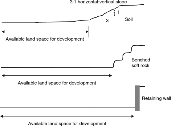
Figure 3.22 Available Land Space for Development with Sloped Soil, Benched Soft Rock, and a Retaining Wall.
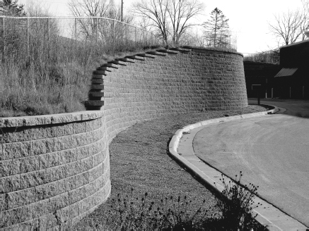
Figure 3.23 A Curved Retaining Wall Made of Block. Note the safety fence above the wall.
Source: M. Penn.
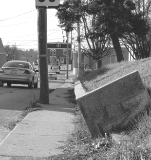
Figure 3.24 An Overturned Concrete Retaining Wall. The face of the wall was vertical when originally constructed.
Source: M. Penn.
Retaining walls are made of many materials depending on the height required, type of geologic material being retained, aesthetics, etc. (Figure 3.23). Structurally, retaining walls must support the lateral earth pressure caused by the downward movement of the geologic formation and the hydrostatic pressure of groundwater (if not properly drained from behind the wall). Improper design or construction may lead to collapse, sliding, or overturning (Figure 3.24).
Lateral earth pressure is the pressure (force per unit area) that soil or rock exerts in the horizontal direction.
Hydrostatic pressure is the pressure exerted by water perpendicular to a surface such as a retaining wall.
Outro
The poor grades assigned by the ASCE Infrastructure Report Card to the sectors pertaining to structures (schools, bridges, dams, and levees and floodwalls) paint a dismal picture of the structural infrastructure. The next two chapters will introduce you to the transportation and the environmental infrastructure, and these sectors also have received very low grades. Keep in mind however, as you read the next two chapters, that the low grades can be raised with adequate funding.
Additional Resources
The following books are highly recommended for further understanding of the infrastructure components presented in this chapter and the following two chapters:
E. Sobey. A Field Guide to Roadside Technology. Chicago: Chicago Review Press, 2006.
K. Ascher. The Works: Anatomy of a City. New York: Penguin Press, 2005
B. Hayes. Infrastructure: The Book of Everything for the Industrial Landscape. New York: W.W. Norton, 2005.
G. Rainer. Understanding Infrastructure. Hoboken, NJ: John Wiley & Sons, 1990.
S. Hule. On the Grid: A Plot of Land, an Average Neighborhood, and the Systems That Make Our World Work. Emmaus, PA: Rodale, 2010.
D. L. Schodek. Landmarks in American Civil Engineering. Boston: MIT Press, 1997.
chapter Three Homework Problems
- 3.1 An existing levee has a top width of 10 feet, a top elevation of 10 feet above the base, and 3:1 (horizontal:vertical) slopes on both sides. If the levee is to be raised to an elevation of 15 feet and must meet new standards requiring a 12-foot top width, how much additional land space (in ft2) will be needed for the base of the levee per mile of levee length? Assume side slopes remain 3:1. Show all work, and support your answer with appropriate drawings and schematics.
- 3.2 When designing a bridge, what considerations must be accounted for in addition to cost?
- 3.3 Why are fish ladders sometimes necessary?
- 3.4 Explain how, for a certain site, the additional cost of a retaining wall might offset the cost of purchasing additional land.
- 3.5 What is the difference between a caisson and a cofferdam?
- 3.6 Why are spillways used?
- 3.7 Sketch the bridge shown in Figure 3.12. On your sketch, show how the loads on the bridge deck are transferred to the subsurface. Also, note which portions of the bridge are in compression and which are in tension.
- 3.8 A new bridge was planned to cross Lake Champlain, which lies between New York State and Vermont. Preliminary designs of several types of bridges were provided (available at www.wiley.com/college/penn). Which one would you select if you were in the position to do so? Why?
- 3.9 Currently, levees in the United States have not been catalogued, nor is there a uniform method for assessing them. Why might this be?
- 3.10 Do you think it is practical to require that all levees should provide protection from greater than 100-year floods? Why or why not?
- 3.11 Photograph a retaining wall in your community from several different angles, including close-up and distance pictures. Describe the wall (height, length, etc.) using a tape measure. Assess the condition of the wall.
Note: For Homework Problems 3.12 through 3.14, 3.16, and 3.18, the ASCE Report Card is available at www.wiley.com/college/penn.
- 3.12 Read the most recent chapter on dams in the ASCE Report Card for America's Infrastructure. Based on the information in this chapter, write a brief (approximately 500 words) letter to your local newspaper in which you voice your concerns over dam safety. Refer to information in the report card chapter to justify your claims.
- 3.13 From the data in the 2009 ASCE Report Card chapter on dams, create a graph of the number of high-hazard dams needing repair for the years 2001 to 2007.
- 3.14 Read the most recent chapter on levees in the ASCE Report Card for America's Infrastructure. Summarize the reasons why levees and floodwalls obtained the assigned grade.
- 3.15 Read the document “So, You Live Behind a Levee!” (available at www.wiley.com/college/penn). In approximately 500 words, explain what you learned and describe what you found most interesting from this article. Also, prepare a list of new (to you) vocabulary presented in the document.
- 3.16 Read the most recent chapter on bridges in the ASCE Report Card for America's Infrastructure. What are some reasons that bridges earned their relatively high grade?
- 3.17 Define “structurally deficient” and “structurally obsolete.” Which one is “worse”? Give some examples of bridge characteristics that would cause that bridge to be classified as: structurally deficient; structurally obsolete.
- 3.18 From the fact sheet on bridges supplied by the 2009 ASCE Report Card chapter on bridges, create a graph that plots the fraction (as a percent) of bridges in the United States that are (a) structurally deficient and that are (b) structurally obsolete for the years 1998 to 2007.
- 3.19 In what types of situations are pilings required for foundations? Do pilings always rest on bedrock?
- 3.20 Visit www.floodsmart.gov. Enter location information (specified by your instructor) into the “One Step Flood Risk Profile” and print out the results.
- 3.21 Use a program such as Microsoft PowerPoint to create a photo gallery that includes photos of each of the bridge types listed in this chapter. Make sure to provide references for photos obtained online.
Key Terms
- abutments
- acre-feet
- caissons
- cofferdams
- fish elevators
- fish ladders
- footings
- high-hazard potential dams
- hydrostatic pressure
- lateral earth pressure
- major dams
- multiple lines of defense
- piles
- sectors
- spillways
- stage
- subsectors
References
American Society of Civil Engineers (ASCE). 2007. The New Orleans Hurricane Protection System: What Went Wrong and Why. Reston, VA: American Society of Civil Engineers.
Association of State Dam Safety Officials (ASDSO). 2007. Statistics on Dams and State Safety Regulation. Lexington, KY.
City of Anderson, Indiana. Emergency Management. http://www.cityofanderson.com/emergency/fws.aspx, accessed July 23,2010.
City of Anderson, Indiana. Flood Warning System. http://www.cityofanderson.com/beta/directory_department_page_view.aspx?id=21&deptid=13, accessed July 23, 2010.
U.S. Army Corps of Engineers (USACE). 2009. Louisiana Coastal Restoration and Protection Final Technical Report and Comment Addendum.
http://lacpr.usace.army.mil/default.aspx?p=LACPR_Final_Technical_Report, accessed August 6, 2011.