
Chapter 5. Thermodynamics of Processes
There cannot be a greater mistake than that of looking superciliously upon practical applications of science. The life and soul of science is its practical application.
Lord Kelvin (William Thompson)
In the first four chapters, we have concentrated on applications of the first and second laws to simple systems (e.g., turbine, throttle). The constraints imposed by the second law should be clear. In this chapter, we show how the analyses we have developed for one or two operations at a time can be assembled into complex processes. In this way, we provide several specific examples of ways that operations can be connected to create power cycles, refrigeration cycles, and liquefaction cycles. We can consider these processes as paradigms for general observations about energy and entropy constraints.
Chapter Objectives: You Should Be Able to...
1. Write energy and entropy balances around multiple pieces of equipment using correct notation including mass flow rates.
2. Simplify energy balances by recognizing when streams have the same properties (e.g., splitter) or flow rates (heat exchanger inlet/outlet).
3. Apply the correct strategy for working through a power cycle with multiple reheaters and feedwater preheaters.
4. For ordinary vapor compression cycles, locate condenser/evaporator P or T given one or the other and plot the process outlet and P-H diagram.
5. Successfully approach complex processes by simplifying the E-balance and S-balance, solving for unknowns.
5.1. The Carnot Steam Cycle
We saw in Example 4.4 on page 145 how a Carnot cycle could be set up using steam as a working fluid. The addition of heat at constant temperature and the macroscopic definition of entropy establish a correspondence between temperature and heat addition/removal. Steam is especially well suited for isothermal heat exchange because boiling and condensation are naturally isothermal and exchange large amounts of heat. To review, we could plot this cycle in T-S coordinates and envision a flow process with a turbine to produce work during adiabatic expansion and some type of compressor for the adiabatic compression as shown in Fig. 5.1. The area inside the P-V cycle represents the work done by the gas in one cycle, and the area enclosed by the T-S path is equal to the net intake of energy as heat by the gas in one cycle.
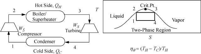
Figure 5.1. Illustration of a Carnot cycle based on steam in T-S coordinates.
The Carnot cycle has a major advantage over other cycles. It operates at the highest temperature available for as long as possible, reducing irreversibilities at the boundary because the system approaches the reservoir temperature during the entire heat transfer. In contrast, other cycles may only approach the hot reservoir temperature for a short segment of the heat transfer. A similar argument holds regarding the low temperature reservoir. Unfortunately, it turns out that it is impossible to make full use of the advantages of the Carnot cycle in practical applications. When steam is used as the working fluid, the Carnot cycle is impractical for three reasons: 1) It is impractical to stay inside the phase envelope because higher temperatures correlate with higher pressure. Higher pressures lead to smaller heat of vaporization to absorb heat. Since the critical point of water is only ~374°C, substantially below the temperatures from combustion, the temperature gradient between a fired heater and the steam would be large; 2) expanding saturated vapor to low-quality (very wet) steam damages turbine blades by rapid erosion due to water droplets; 3) compressing a partially condensed fluid is much more complex than compressing an entirely condensed liquid. Therefore, most power plants are based on modifications of the Rankine cycle, discussed below. Nevertheless, the Carnot cycle is so simple that it provides a useful estimate for checking results from calculations regarding other cycles.
5.2. The Rankine Cycle
In a Rankine cycle, the vapor is superheated before entering the turbine. The superheat is adjusted to avoid the turbine blade erosion from low-quality steam. Similarly, the condenser completely reduces the steam to a liquid that is convenient for pumping.
In Fig. 5.2, state 4′ is the outlet state for a reversible adiabatic turbine. We use the prime (′) to denote a reversible outlet state as in the previous chapter. State 4 is the actual outlet state which is calculated by applying the efficiency to the enthalpy change.

Figure 5.2. Rankine cycle.
Because a real turbine always generates entropy, state 4 will always be to the right of 4′ on a T-S diagram. States 4 and 4′ can be inside or outside the phase envelope. Efficiencies are greater if state 4 is slightly inside the phase envelope because the enthalpy change will be larger for the same pressure drop due to the large enthalpy of vaporization; however, to avoid turbine blade damage, quality is kept above 90% in most cases.
Note in Fig. 5.2 that the superheater between the boiler and the turbine is not drawn, and only a single unit is shown. In actual power plants, separate superheaters are used; however, for the sake of simplicity in our discussions the boiler/superheater steam generator combination will be represented by a single unit in the schematic.
Turbine calculation principles were covered in the last chapter. Now we recognize that the net work is the sum of the work for the turbine and pump and that some of the energy produced by the turbine is needed for the pump. In general, the thermal efficiency is given by:
The boiler input can be calculated directly from the enthalpy out of the pump and the desired turbine inlet. The key steps are illustrated in Example 5.1.
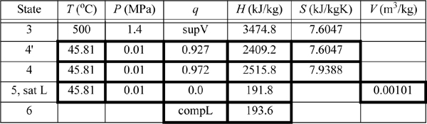
A power plant uses the Rankine cycle. The turbine inlet is 500°C and 1.4 MPa. The outlet is 0.01 MPa. The turbine has an efficiency of 85% and the pump has an efficiency of 80%. Determine:
a. The work done by the turbine (kJ/kg)
b. The work done by the pump, the heat required, and the thermal efficiency;
c. The circulation rate to provide 1 MW net power output.
Solution
We will refer to Fig. 5.2 for stream numbers. The recommended method for solving process problems is to establish a table to record values as they are determined. In this text we will show values in the tables with bold borders if they have been determined by balance calculations. The turbine outlet can be read from the temperature table without interpolation. Cells with standard borders refer to properties determined directly from the problem statement
![]() Boldfaced table cells show calculations that were determined by balances. We follow this convention in the following examples.
Boldfaced table cells show calculations that were determined by balances. We follow this convention in the following examples.
Because the turbine inlet has two state variables specified, the remainder of the state properties are found from the steam tables and tabulated in the property table. We indicate a superheated vapor with “supV” compressed liquid with “compL.”
a. Stepping forward across the turbine involves the same specifications as part (c) of Example 4.13 on page 168. The properties from 4 and 4′ are transferred from that example to the property table. The work done is –959 kJ/kg.
b. The outlet of the condenser is taken as saturated liquid at the specified pressure, and those values are entered into the table. We must calculate ![]() and
and ![]() . So we need H6 and WS,pump which are determined by calculating the adiabatic work input by the pump to increase the pressure from state 5. Although the reversible calculation for the pump is isentropic, we may apply Eqn. 2.61 without direct use of entropy, and then correct for efficiency. For the pump,
. So we need H6 and WS,pump which are determined by calculating the adiabatic work input by the pump to increase the pressure from state 5. Although the reversible calculation for the pump is isentropic, we may apply Eqn. 2.61 without direct use of entropy, and then correct for efficiency. For the pump,
Thus, the work of the pump is small, resulting in H6 = 191.8 + 1.8 = 193.6 kJ/kg. The net work is W’S,net = –959.0 + 1.8 = 957.2 kJ/kg. The only source of heat for the cycle is the boiler/superheater. All of the heat input is at the boiler/superheater. The energy balance gives QH = (H3 – H6) = 3281.2 kJ/kg. The thermal efficiency is
If we neglected the pump work, the efficiency would 29.23%. Note that the pump work has only a small effect on the thermal efficiency but is included for theoretical rigor.
c. For 1 MW capacity, ![]() , the circulation rate is
, the circulation rate is
The cycle in Fig. 5.2 is idealized from a real process because the inlet to the pump is considered saturated. In a real process, it will be subcooled to avoid difficulties (e.g., cavitation1) in pumping. In fact, real processes will have temperature and pressure changes along the piping between individual components in the schematic, but these changes will be considered negligible in the Rankine cycle and all other processes discussed in the chapter, unless otherwise stated. These simplifications allow focus on the most important concepts, but the simplifications would be reconsidered in a detailed process design.
5.3. Rankine Modifications
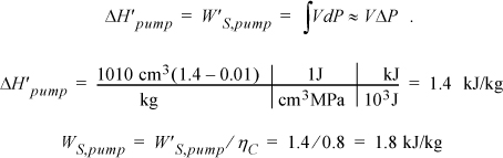
Two modifications of the Rankine cycle are in common use to improve the efficiency. A Rankine cycle with reheat increases the boiler pressure but keeps the maximum temperature approximately the same. The maximum temperatures of the boilers are limited by corrosion concerns. This modification uses a two-stage turbine with reheat in-between. An illustration of the modified cycle is shown in Fig. 5.3. Crudely, adding multiple stages with reheat leads to the maximum temperature being applied as much as possible, while avoiding extremely wet steam during expansion. This moves the process efficiency in the direction of a Carnot cycle. The implication of this modification is shown in Example 5.2.
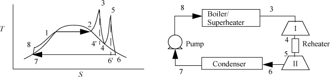
Figure 5.3. Rankine cycle with reheat.
Example 5.2. A Rankine cycle with reheat
Consider a modification of Example 5.1. If we limit the process to a 500°C boiler/superheater with reheat, we can develop a new cycle to investigate an improvement in efficiency and circulation rate. Let us operate a cycle utilizing two reversible turbines with ηE = 0.85 and a pump with ηC = 0.8. Let the feed to the first turbine be steam at 500°C and 6 MPa. Let the feed to the second stage be 1.4 MPa and 500°C (the same as Example 5.1). Determine the improvement in efficiency and circulation rate relative to Example 5.1.
Solution
Refer to Fig. 5.3 for stream numbers. First, let us find state 3. The inlet state values are entered in the table. P4 = P5 because we neglect the heat exchanger pressure drop. Upon expansion through the first reversible turbine, we look at the SsatV at 1.4 MPa and find it lower that S4’. Therefore, the reversible state is superheated. Using {S,P} to find H,
Correcting for efficiency,
ΔHI = WS, I = 0.85(3001.2 – 3423.1) = 0.85(–421.9) = –358.6 kJ/kg
H4 = 3423.1 – 358.6 = 3064.5 kJ/kg

State 5 was used in Example 5.1 (as state 3). Solving the energy balance for the reheater,
Qreheat = (H5 – H4) = 3474.8 – 3064.5 = 410.3 kJ/kg
Turbine II was analyzed in Example 5.1. We found WS,II = –959.0 kJ/kg and the total work output is WS,turbines = (–358.6 –959.0) = –1317.6 kJ/kg. The pump must raise the pressure to 6 MPa. Using Eqn. 2.61, and correcting for efficiency,
State 7 is the same as state 5 in Example 5.1 and has been tabulated in the property table. H8 = H7 + WS,pump = 191.8 + 7.6 = 199.4 kJ/kg. The net work is thus
WS, net = –1317.6 + 7.6 = –1310 kJ/kg
The heat for the boiler/superheater is given by Qb/s = H3 – H8 = 3423.1 – 199.4 = 3223.7 kJ/kg.
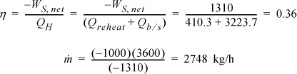
The efficiency has improved by ![]() , and the circulation rate has been decreased by 27%.
, and the circulation rate has been decreased by 27%.
One variation of the Rankine cycle is for cogeneration as illustrated in Fig. 5.4. Most chemical plants need process steam for heating distillation columns or reactors as well as electrical energy. Therefore, they use steam at intermediate pressures, depending on the need, and circulate the condensate back to the boiler. Another very common modification of the Rankine cycle is a regenerative cycle using feedwater preheaters. A portion of high-pressure steam is used to preheat the water as it passes from the pump back to the boiler. A schematic of such a process is shown in Fig. 5.5 using closed feedwater preheaters. The economic favorability increases until about five preheaters are used, then the improvements are not worth the extra cost. Three preheaters are more common. As the condensate from each preheater enters the next preheater, it throttles through a valve to the next lower pressure and partially or totally vaporizes as it throttles. It is also common to withdraw some steam from turbine outlets for process use and heating. Often in actual processes, open feedwater preheaters are used. In an open feedwater preheater, all of the incoming streams mix. The advantage of this preheater is that dissolved oxygen in the returning condensate can be removed by heating, and if provision is made to vent the non-condensables from the open feedwater preheater, it may serve as a deaerator to remove dissolved air before feeding the boiler. A system with an open feedwater preheater is shown in Fig. 5.6. The vent on the open feedwater preheater is typically a small stream and omitted in the schematics and first order calculations. A regenerative Rankine cycle is illustrated in Example 5.3.
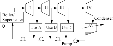
Figure 5.4. Rankine cycle with side draws for process steam. Pumps and/or throttles may be used in returning process steam to the boiler.
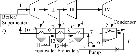
Figure 5.5. Regenerative Rankine cycle using closed feedwater preheaters.
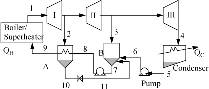
Figure 5.6. Schematic for a system with a closed feedwater preheater, A, and an open feedwater preheater, B.
Example 5.3. Regenerative Rankine cycle
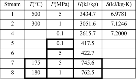
Steam (1) exits a boiler/superheater at 500°C and 5 MPa. A process schematic is shown in Fig. 5.7. The first stage of the turbine exits (2, 3) at 1MPa and the second stage of the turbine exits (4) at 0.1 MPa. A feed preheater is used to exchange heat with a 5°C approach temperature between streams 7 and 8. Find the net power output per kg of flow in stream 1.

Figure 5.7. Regenerative Rankine cycle for Example 5.3.
First, note that streams 2 and 8 are on the same side of the feedwater preheater and are thus at the same pressure. Streams 7 and 6 must be at the boiler pressure by similar arguments. And stream 5 must likewise be at the condenser pressure. Stream 8 leaves as saturated liquid at the 1 MPa, thus we find H8 = 762.5 kJ/kg, and T8 = 180°C. Stream 7 is thus at 175°C and 5 MPa. Following Example 2.6 for a compressed liquid, H7 = 741.02kJ/kg + (5–0.893MPa)(1.12cm3/g) = 745.6 kJ/kg. Often, one of the key steps in working a problem involving a regenerative cycle is to solve for the fraction of each flow diverted rather than solving for the individual flow rates.
![]() Solving for flowrate ratios in regenerative cycles can be helpful when the total flowrate is unknown.
Solving for flowrate ratios in regenerative cycles can be helpful when the total flowrate is unknown.
The flow rates of streams 7, 6, and 5 are equal to the flow rate of stream 1, and we may write the energy balance around the feedwater preheater using the mass flow rate of stream 1 together with the mass flow rate of stream 2, ![]() . Dividing by
. Dividing by ![]() and substituting values gives
and substituting values gives ![]() , and
, and ![]() .
.
The net work is given by ![]() , and on the basis of one kg from the boiler/superheater,
, and on the basis of one kg from the boiler/superheater, ![]() , and using enthalpies to calculate the work of each turbine,
, and using enthalpies to calculate the work of each turbine,
Referring to the tabulated values,
When you consider all combinations of reheat and regeneration, it is clear that the number of configurations of turbine stages and heat exchangers is nearly endless. Practically speaking, one approaches a point of diminishing returns with each added complexity. The best alternative may depend on details of the specific application. Broadly speaking, Example 5.2 shows a clear 24% gain in thermal efficiency by using reheat. Example 5.3 is not at the same conditions as Example 5.1, but we can quickly estimate the thermal efficiency at the same conditions as ηθ = (3435 – 2617)/(3435 – 422) = 0.271, so regeneration alone offers just a 3% gain. A dedicated electric power facility would definitely want to make the most of every gain, but a small power generator for a chemical facility in an isolated rural area might be subject to other constraints. For example, the need for medium pressure steam to run distillation columns might dictate the pressure for the intermediate stage and a similar need for building heat could dictate a lower temperature requirement. In the final analysis, it is up to the engineer to devise the best solution by adapting these examples and general observations to any particular situation.
5.4. Refrigeration
Ordinary Vapor Compression Cycle
The Carnot cycle is not practical for refrigeration for the same reasons as discussed for power production. Therefore, most refrigerators operate on the ordinary vapor-compression (OVC) cycle, shown in Fig. 5.8.
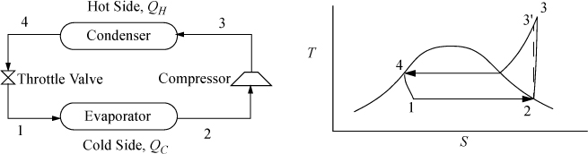
Figure 5.8. OVC refrigeration cycle process schematic and T-S diagram.
As with the Rankine cycle, we make some simplifications that would have to be reevaluated in a detailed engineering design. Again, we neglect pressure losses in piping. We assume that the vapor is saturated at the inlet to the compressor, and that the outlet of the condenser is saturated liquid. Thus, saturated vapor enters the compressor and exits heated above the condenser temperature, then cools in the condenser until it condenses to a saturated liquid. In the cyclic process, the saturated liquid is passed through a throttle valve at constant enthalpy and exits as a two-phase mixture. The evaporator is assumed to be isothermal, and accepts heat at the colder temperature to complete the vaporization. The OVC cycle is often characterized using a P-H diagram as shown in Fig. 5.9.

Figure 5.9. OVC refrigeration cycle plotted on the more commonly used P-H diagram. State numbers correspond to Fig. 5.8.
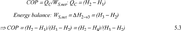
The COP can be related to the conditions of the process streams.
Example 5.4. Refrigeration by vapor compression cycle
An industrial freezer room is to be maintained at –15°C by a cooling unit utilizing refrigerant R134a as the working fluid. The evaporator coils should be maintained at –20°C to ensure efficient heat transfer. Cooling water is available at 10°C from an on-site water well and can be warmed to 25°C in the condenser. The refrigerant temperature exiting the condenser is to be 30°C. The cooling capacity of the freezer unit is to be 120,000 BTU/h (126,500 kJ/h); 12,650 kJ/h is known as one ton of refrigeration because it is approximately the cooling rate (cooling duty) required to freeze one ton of water at 0°C to one ton of ice at 0°C in 24 h. So this refrigerator represents a 10 ton refrigerator. As a common frame of reference, typical home air conditioners are about 2–3 tons, but they typically weigh less than 100 kg. Calculate the COP and recirculation rate (except part (a)) for the industrial freezer in the following cases:
a. Carnot cycle.
b. Ordinary vapor compression cycle with a reversible compressor.
c. Vapor compression cycle with the throttle valve replaced with an expander.
d. Ordinary vapor compression cycle for which compressor is 80% efficient.
Solution
We will refer to Fig. 5.8 for identifying state by number. The operating temperatures of the refrigeration unit will be
a. Carnot cycle
Note that T3 will be higher than T4, but we use the condenser outlet T4 as the benchmark temperature.
b. Ordinary VC cycle with reversible compressor
We will create a table to summarize results. Values determined from balances are shown in boldfaced table cells. Other valves are from the R-134a chart in Appendix E. State 2 is a convenient place to start since it is a saturated vapor and the temperature is known. T2 = –20°C, from the chart, H2satV = 386.5 kJ/kg and S2satV = 1.7414 kJ/kg-K. The condenser outlet (state 4) is taken as saturated liquid at 30°C, so the pressure of the condenser will be P4sat (30°C) = 0.77 MPa, and H4 = 241.5 kJ/kg, S4 = 1.1428 kJ/kg-K. Because the throttle valve is isenthalpic (Section 2.13), H1 = H4.
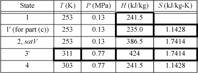
The compressor calculation has already been performed in Example 4.17 on page 174. If the process is reversible, the entropy at state 3′ will be the same as S2. Finding H3′ from S3′ = 1.7414 kJ/kg-K and P3 = 0.77 MPa, using the chart, H3′ = 424 kJ/kg. Note that the pressure in the condenser, not the condenser temperature, fixes the endpoint on the isentropic line from the saturated vapor.
The required circulation rate is
c. VC cycle with turbine expansion
The throttle valve will be replaced by a reversible expander. Therefore, S1′ = S4 = 1.1428 kJ/kg-K. The saturation values at 253 K are SsatL = 0.8994 kJ/kg-K and SsatV = 1.7414 kJ/kg-K; therefore, S1′ = 1.1428 = q’·1.7414 + (1 – q’)0.8994, which gives q’ = 0.289.
Then, using the saturated enthalpy values and the quality, H1′ = 235.0 kJ/kg. In order to calculate the COP, we must recognize that we are able to recover some work from the expander, given by H1′ – H4.
The increase in COP requires a significant increase in equipment complexity and cost, since a two-phase expander would probably have a short life due to erosion of turbine blades by droplets.
d. Like (b) but with irreversible compressor
States 1, 2, and 4 are the same as in (b). The irreversibility simply changes state 3.
Refrigerant choice is dictated by several factors:
1. Environmental impact (Freon R-12 depletes ozone and has been phased out; Freon R-22 is being phased out). HFO1234yf is beginning to supersede R134a.
2. Vapor pressure ~ atmospheric at Tevap. Consequently, the driving force for leakage will be small, but an evaporator pressure slightly above atmospheric pressure is desirable to avoid air leaking into the cycle.
3. Vapor pressure not too high at TH so that the operating pressure is not too high; high pressure increases compressor and equipment costs.
4. High heat of vaporization per unit mass.
5. Small CP/CV of vapor to minimize temperature rise and work of compressor.
6. High heat transfer coefficient in vapor and liquid.
Flash Chamber (Economizer) Intercooling
When the temperature difference between the condenser and evaporator is increased, the compressor must span larger pressure ranges. If the compression ratio (Pout/Pin) becomes too large, interstage cooling can be used to increase efficiency. Because the process temperatures are usually below cooling water temperatures, a portion of the condensed refrigerant stream can be flashed to provide the interstage cooling, as shown in Fig. 5.10. The interstage cooler is sometimes called an economizer. The economizer is considered adiabatic unless otherwise specified, and serves to disengage the liquid and vapor exiting the inlet valve. The quality out of the inlet valve is equal to ![]() .
.
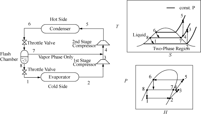
Figure 5.10. Flash chamber intercooling.
Cascade Refrigeration
In order to span extremely large temperature ranges, a single refrigerant becomes impractical, because the compression ratio (Pout/Pin) becomes too high and the COP decreases. A typical guideline is that the compression ratio should not be higher than about 8. Therefore, to span extremely large ranges, binary vapor cycles or cascade vapor cycles are used. In a binary cycle, a refrigerant with a normal boiling point below the coldest temperature is used on the cold cycle, and a refrigerant that condenses at a moderate pressure is used on the hot cycle. The two cycles are coupled at the condenser of the cold cycle and the evaporator of the hot cycle as shown in Fig. 5.11. Because the heat of vaporization is coupled to the saturation temperature for any refrigerant, usually the operating temperatures are selected, and the circulation rates are determined for each cycle. Certainly, there are many variables to optimize in a process design of this type. For extremely large ranges, such as for cryogenic processing of liquefied gases, cascade refrigeration can be used with multiple cycles. For example, for the liquefaction of natural gas, the three cycles might be ammonia, ethylene, and methane. Note that the evaporator in each cycle must be colder than the condenser of the cycle below to ensure heat is transferred in the correct direction.
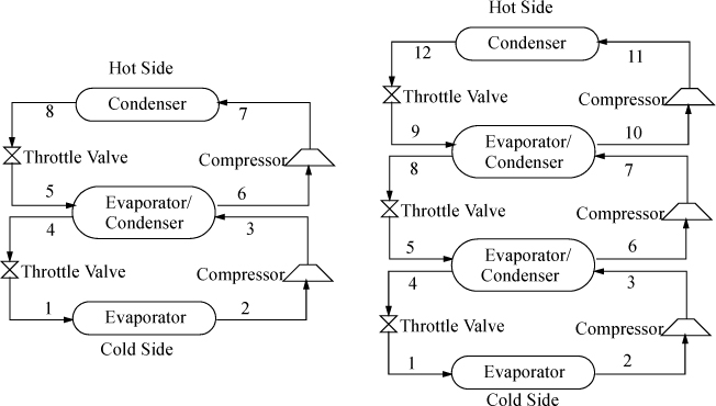
Figure 5.11. Binary cycle (left) and three-cycle cascade (right) refrigeration cycles. The refrigerants do not mix in the evaporator/condensers.
5.5. Liquefaction
We have encountered liquefaction since our first quality calculation in dealing with turbines. In refrigeration, throttling or isentropic expansion results in a partially liquid stream. The point of a liquefaction process is simply to recover the liquid part as the primary product.
Linde Liquefaction
The Linde process works by throttling high-pressure vapor. The Joule-Thomson coefficient, ![]() , must be such that the gas cools on expansion,2 and the temperature must be low enough and the pressure high enough to ensure that the expansion will end in the two-phase region. Since less than 100% is liquefied, the vapor phase is returned to the compressor, and the liquid phase is withdrawn. Multistage compression is usually used in the Linde liquefaction process to achieve the required high pressures. An example of the process pathways on a T-S diagram is shown in Fig. 5.12. The actual state of the gas entering the multistage compressor depends on the state of the feed.
, must be such that the gas cools on expansion,2 and the temperature must be low enough and the pressure high enough to ensure that the expansion will end in the two-phase region. Since less than 100% is liquefied, the vapor phase is returned to the compressor, and the liquid phase is withdrawn. Multistage compression is usually used in the Linde liquefaction process to achieve the required high pressures. An example of the process pathways on a T-S diagram is shown in Fig. 5.12. The actual state of the gas entering the multistage compressor depends on the state of the feed.
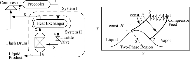
Figure 5.12. Linde liquefaction process schematic. The system boundaries shown on the left are used in Example 5.5.
Example 5.5. Liquefaction of methane by the Linde process
Methane is to be liquefied in a simple Linde process. The feed and recycle are mixed, compressed to 60 bar, and precooled to 300 K. The vapor then passes through a heat exchanger for additional cooling before being throttled to 1 bar. The unliquefied fraction leaves the separator at the saturation temperature, and passes through the heat exchanger, then exits at 295 K. (a) What fraction of the gas is liquefied in the process; and (b) what is the temperature of the high-pressure gas entering the throttle valve?
Solution
The schematic is shown in Fig. 5.12. To solve this problem, first recognize that states 3, 6, 7, and 8 are known. State 3 is at 300 K and 60 bar; state 6 is saturated liquid at 1 bar; state 7 is saturated vapor at 1 bar; and state 8 is at 295 K and 1 bar. Use the furnished methane chart from Appendix E.
a. The System I energy balance is: H3 – [qH8 + (1 – q)H6] = 0
b. The energy balance for System II is: H4 – H3 = –q(H8 – H7) = –0.9286(1195 – 796.1) = –370.5 ⇒ H4 = 780
⇒ H4 = 780 @ 60 bar ⇒ chart gives –95°F = 203 K
Claude Liquefaction
The throttling process between states 4 and 5 in the Linde process is irreversible. To improve this, a reversible expansion is desirable; however, since the objective is to liquefy large fractions of the inlet stream, turbines are not practical because they cannot handle low-quality mixtures. One compromise, the Claude liquefaction, is to expand a portion of the high-pressure fluid in an expander under conditions that avoid the two-phase region, as shown in Fig. 5.13. Only a smaller fraction of the compressed gas enters the irreversible throttle valve, so the overall efficiency can be higher but more sophisticated equipment is required.
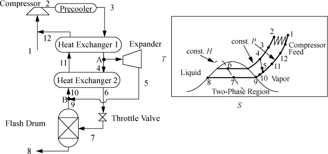
Figure 5.13. The Claude liquefaction process.
5.6. Engines
Steam is not the only working fluid that can be used in a power producing cycle. A common alternative is to use air, mixed with a small amount of fuel that is burned. The heat of combustion provides energy to heat the gas mixture before it does work in an expansion step. A major benefit of using air is that a physical loop is not necessary; we can imagine the atmosphere as the recycle loop. This approach forms the basis for internal combustion engines like lawn mowers, jet engines, diesels, and autos. An online supplement introduces the gas turbine, the turbofan jet engine, the internal combustion engine, and the diesel engine.
5.7. Fluid Flow
This section is available as an on-line supplement and includes liquids and compressible gases. We discuss the energy balance, the Bernoulli equation, friction factor, and lost work. We also generalize that ![]() is a general result for open system compressors that are not adiabatic.
is a general result for open system compressors that are not adiabatic.
5.8. Problem-Solving Strategies
As you set up more complex problems, use the strategies in Section 2.14 on page 74, and incorporate the energy balances developed in Section 2.13 on page 68 for valves, nozzles, heat exchangers, turbines, and pumps and entropy balances developed in Section 4.6 on page 159 for turbines, compressors, and heat pumps/engines as you work through step 5 of the strategies. A stream that exits a condenser is assumed to exit as saturated liquid unless otherwise specified. Likewise, a stream that is vaporized in a boiler is assumed to exit saturated unless otherwise specified; however, recall that in a Rankine cycle the steam is always superheated, and we omit the superheater unit in schematics for simplicity. Read problem statements carefully to identify the outlet states of turbines. Outlets of turbines are not required to be saturated or in the two-phase region, although operation in this manner is common. In a multistage turbine without reheat, only the last stages will be near saturation unless reheat is used. Unless specified, pressure drops are considered negligible in piping and heat exchangers as a first approximation. Throttle valves are assumed to be adiabatic unless otherwise stated, and they are always irreversible and do have an important pressure drop unless otherwise stated. Recognize that the entropy balances for throttle valves or heat exchangers are usually not helpful since, in practical applications, these devices are inherently irreversible and generate entropy.
Recognize that the energy balance must be used often to find mass flow rates. In order to do this for open steady-state flow systems, the enthalpies for all streams must be known in addition to the mass flow rates for all but one stream. You can try moving the system boundary as suggested in step 7 of the strategy in Section 2.14 on page 74 to search for balances that satisfy these conditions. Mass flow rates can be found using the entropy balance also, but this is not done very often, since the entropy balance is useful only if the process is internally reversible or if the rate of entropy generation is known (i.e., no irreversible heat exchangers or throttle valves or irreversible turbines/compressors inside the system boundary).
Basically, the energy and entropy balance and the P-V-T relation are the only equations that always apply. While we have shown common simplifications, there are always new applications that can arise, and it is wise to learn the principles involved in simplifying the balance to a given situation.
5.9. Summary
Similar to energy balances in Chapter 3, entropy balances can be applied to composite systems. What is new in this chapter is the level of detail and the combination of the energy balance with the entropy balance. Instead of abstract processes like the Carnot cycle, the entropy balance enables us to compute the impacts of each individual step, whether isothermal, irreversible, or otherwise. This leads to composite processes with innumerable combinations of heat exchangers, multiple stages, and mixers, all striving to achieve the efficiency of the Carnot or Stirling cycles. For processes on the scale of commercial production, an efficiency improvement of 0.1% can mean millions of dollars, amply justifying an investment in clever engineering.
Important Equations
Once again the energy and entropy balances are the most important equations. We have incorporated most of the previous chapters, using state properties, interpolations, efficiency calculations, throttling, and so on. Carnot thermal efficiency and COP provide upper bounds on what can be achieved with any process and these are important.
5.10. Practice Problems
P5.1. An ordinary vapor compression cycle is to operate a refrigerator on R134a between –40°C and 40°C (condenser temperatures). Compute the coefficient of performance and the heat removed from the refrigerator per day if the power used by the refrigerator is 9000 J per day. (ANS. 1.76)
P5.2. An ordinary vapor compression cycle is to be operated on methane to cool a chamber to –260°F. Heat will be rejected to liquid ethylene at –165°F. The temperatures in the condenser and evaporator are –160°F and –280°F. Compute the coefficient of performance. (ANS. 0.86)
P5.3. A simple Rankine cycle is to operate on steam between 200°C and 99.6°C, with saturated steam exhausting from the turbine. What is the maximum possible value for its thermodynamic efficiency? (ANS. 7.8%)
P5.4. An ordinary vapor compression cycle is to be operated on methane to cool a chamber to 112 K. Heat is rejected to liquid ethylene at 160 K. The temperatures in the coils are 168 K and 100 K. (ANS. online)
a. Write the relevant energy and entropy balances for the compression step.
b. Estimate the minimal work requirement (J/g) for the compressor assuming the ideal gas law.
c. Estimate the coefficient of performance (COP) for this OVC cycle.
d. Estimate the COP by the Carnot guideline.
e. Estimate the minimal work requirement for the compressor using the chart in the text.
P5.5. A house has an effective heat loss of 100,000 Btu/hr. During the heating season of 160 days the average inside temperature should be 70°F while the outside is 45°F. Freon-134a is the working fluid and an ordinary vapor-compression cycle is used. A 10°F approach on each side may be assumed. Electricity costs $0.14/KW-hr.
a. What is the cost in $/hr if the compressor is 100% efficient?
b. What is the cost if the compressor is 80% efficient? (ANS. ~0.37, 0.45)
P5.6. An adiabatic turbine is supplied with steam at 300 psia and 550°F that exhausts at atmospheric pressure. The quality of the exhaust steam is 95%.
a. What is the efficiency of the turbine? (ANS. 76%)
b. What would be the thermodynamic efficiency of a Rankine cycle operated using this turbine at these conditions? (ANS. 17%)
5.11. Homework Problems
5.1. A steam power plant operates on the Rankine cycle according to the specified conditions below. Using stream numbering from Fig. 5.2 on page 201, for each of the options below, determine:
a. The work output of the turbine per kg of steam;
b. The work input of the feedwater pump per kg of circulated water;
c. The flowrate of steam required;
d. The heat input required in the boiler/superheater;
e. The thermal efficiency

5.2. A steam power plant operates on the Rankine cycle with reheat, using the specified conditions below. Using stream numbering from Fig. 5.3 on page 203, for each of the options below, determine
a. The work output of each turbine per kg of steam;
b. The work input of the feedwater pump per kg of circulated water;
c. The flowrate of steam required;
d. The heat input required in the boiler/superheater and reheater;
e. The thermal efficiency.
5.3. A modified Rankine cycle using a single feedwater preheater as shown in Fig. 5.7 on page 206 has the following characteristics.
a. The inlet to the first turbine is at 500°C and 0.8 MPa.
b. The feedwater preheater reheats the recirculated water so that stream 7 is 140°C, and steam at 0.4 MPa is withdrawn from the outlet of the first turbine to perform the heating.
c. The efficiency of each turbine and pump is 79%.
d. The output of the plant is to be 1 MW.
e. The output of the second turbine is to be 0.025 MPa.
Determine the flow rates of streams 1 and 8 and the quality of stream 9 entering the condenser (after the throttle valve). Use the stream numbers from Fig. 5.7 on page 206 to label streams in your solution.
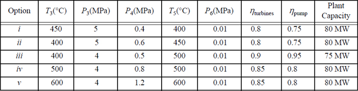
5.4. A modified Rankine cycle uses reheat and one closed feedwater preheater. The schematic is a modification of Fig. 5.7 on page 206 obtained by adding a reheater between the T-joint and turbine II. Letting stream 3 denote the inlet to the reheater, and stream 3a denote the inlet to the turbine, the conditions are given below. The plant capacity is to be 80 MW. Other constraints are as follows: The efficiency of each turbine stage is 85%; the pump efficiency is 80%; and the feedwater leaving the closed preheater is 5°C below the temperature of the condensate draining from the bottom of the closed preheater. For the options below, calculate:
a. The flowrate of stream 1;
b. The thermal efficiency of the plant;
c. The size of the feedwater pump (kW);
i. T1 = 500°C, P1 = 4 MPa, P2 = 0.8 MPa, T3a = 500°C, P4 = 0.01 MPa.
ii. T1 = 600°C, P1 = 4 MPa, P2 = 1.2 MPa, T3a = 600°C, P4 = 0.01 MPa.
5.5. A regenerative Rankine cycle uses one open feedwater preheater and one closed feedwater preheater. Using the stream numbering from Fig. 5.6 on page 206, and the specified conditions below, the plant capacity is to be 75 MW. Other constraints are as follows: The efficiency of each turbine stage is 85%; the pump efficiencies are 80%; and the feedwater leaving the closed preheater is 5°C below the temperature of the condensate draining from the bottom of the closed preheater. For the options below, calculate
a. The flowrate of stream 1.
b. The thermal efficiency of the plant.
c. The size of the feedwater pumps (kW).
Options:
i. The conditions are T1 = 500°C, P1 = 4 MPa, P2 = 0.7 MPa, P3 = 0.12 MPa, and P4 = 0.02 MPa.
ii. The conditions are T1 = 600°C, P1 = 4 MPa, P2 = 1.6 MPa, P3 = 0.8 MPa, and P4 = 0.01 MPa.
5.6. A regenerative Rankine cycle utilized the schematic of Fig. 5.6 on page 206. Conditions are as follows: stream 1, 450°C, 3 MPa; stream 2, 250°C, 0.4 MPa; stream 3, 150°C, 0.1 MPa; stream 4, 0.01 MPa; stream 9, 140°C, H = 592 kJ/kg.
a. Determine the pressures for streams 5, 6, 8, 9, and 10.
b. Determine ![]() .
.
c. Determine the enthalpies of streams 5 and 6 if the pump is 80% efficient.
d. Determine the efficiency of turbine stage I.
e. Determine the output of turbine stage III per kg of stream 4 if the turbine is 80% efficient.
f. Determine ![]() .
.
g. Determine the work output of the system per kg of stream 1 circulated.
5.7. A regenerative Rankine cycle uses three closed feedwater preheaters. Using the stream numbering from Fig. 5.5 on page 205, and the specified conditions below, the plant capacity is to be 80 MW. Other constraints are as follows: The efficiency of each turbine stage is 88%; the pump efficiency is 80%; and the feedwater leaving each preheater is 5°C below the temperature of the condensate draining from the bottom of each preheater. For the options below, calculate:
a. The flowrate of stream 1
b. The thermal efficiency of the plant
c. The size of the feedwater pump (kW)
Options:
i. The conditions are T1 = 700°C, P1 = 4 MPa, P2 = 1 MPa, P3 = 0.3 MPa, P4 = 0.075 MPa, and P5 = 0.01 MPa.
ii. The conditions are T1 = 750°C, P1 = 4.5 MPa, P2 = 1.2 MPa, P3 = 0.4 MPa, P4 = 0.05 MPa, and P5 = 0.01 MPa.
5.8. An ordinary vapor compression refrigerator is to operate on refrigerant R134a with evaporator and condenser temperatures at –20°C and 35°C. Assume the compressor is reversible.
a. Make a table summarizing the nature (e.g., saturated, superheated, temperature, pressure, and H) of each point in the process.
b. Compute the coefficient of performance for this cycle and compare it to the Carnot cycle value.
c. If the compressor in the cycle were driven by a 1 hp motor, what would be the tonnage rating of the refrigerator? Neglect losses in the motor.
5.9. An ordinary vapor compression refrigeration cycle using R134a is to operate with a condenser at 45°C and an evaporator at –10°C. The compressor is 80% efficient.
a. Determine the amount of cooling per kg of R134a circulated.
b. Determine the amount of heat rejected per kg of R134a circulated.
c. Determine the work required per kg of R134a circulated, and the COP.
5.10. An ordinary vapor compression cycle using propane operates at temperatures of 240 K in the cold heat exchanger, and 280 K in the hot heat exchanger. How much work is required per kg of propane circulated if the compressor is 80% efficient? What cooling capacity is provided per kg of propane circulated? How is the cooling capacity per kg of propane affected by lowering the pressure of the hot heat exchanger, while keeping the cold heat exchanger pressure the same?
5.11. The low-temperature condenser of a distillation column is to be operated using a propane refrigeration unit. The evaporator is to operate at –20°C. The cooling duty is to be 10,000,000 kJ/hr. The compressor is to be a two-stage compressor with an adiabatic efficiency of 80% (each stage). The compression ratio (Pout/Pin) for each stage is to be the same. The condenser outlet is to be at 50°C. Refer to Fig. 5.8 on page 208 for stream numbers.
a. Find the condenser, evaporator, and compressor interstage pressures.
b. Find the refrigerant flowrate through each compressor.
c. Find the work input required for each compressor.
d. Find the cooling rate needed in the condenser.
5.12. Solve problem 5.11 using an economizer at the intermediate pressure and referring to Fig. 5.10 on page 211 for stream numbers.
5.13. A refrigeration process with interstage cooling uses refrigerant R134a. The outlet of the condenser is to be saturated liquid at 40°C. The evaporator is to operate at –20°C, and the outlet is saturated vapor. The economizer is to operate at 10°C. Refer to Fig. 5.10 on page 211 for stream numbers in your solution.
a. Determine the required flowrate of stream 1 if the cooling capacity of the unit is to be 8250 kJ/h.
b. Determine the pressure of stream 3, and the work required by the first compressor if it has an efficiency of 85%.
c. What are the flowrates of streams 7 and 6?
d. What is the enthalpy of stream 4?
e. Determine the work required by the second compressor (85% efficient) and the COP.
5.14. A refrigeration process with interstage cooling uses refrigerant R134a, and the outlet of the condenser is to be saturated liquid at 40°C. Refer to Fig. 5.10 on page 211 for stream numbers in your solution. The pressure of the flash chamber and the intermediate pressure between compressors is to be 290 kPa. The evaporator is to operate at –20°C and the outlet is to be saturated vapor. The flow rate of stream 1 is 23 kg/h. The flash chamber may be considered adiabatic. The compressors may be considered to be 80% efficient. Attach the P-H chart with your solution.
a. What is the work input required to the first compressor in kJ/h?
b. What are the flow rates of streams 7 and 6?
c. What is the enthalpy of stream 4?
5.15. The Claude liquefaction process is to be applied to methane. Using the schematic of Fig. 5.13 on page 214 for stream numbering, the key variables depend on the fraction of stream 3 that is liquefied, ![]() , and the fraction of stream 3 that is fed through the expander,
, and the fraction of stream 3 that is fed through the expander, ![]() . Create a table listing all streams from low to high stream numbers. Fill in the table as you complete the problem sections. Attach a P-H diagram with your solution.
. Create a table listing all streams from low to high stream numbers. Fill in the table as you complete the problem sections. Attach a P-H diagram with your solution.
a. Write a mass balance for the system boundary encompassing all equipment except the compressor and precooler.
b. Write an energy balance for the same boundary described in part (a), and show
c. Stream 3 is to be 300 K and 3 MPa, stream 4 is to be 280 K and 3 MPa, stream 12 is to be 290 K and 0.1 MPa, and the flash drum is to operate at 0.1 MPa. The expander has an efficiency of 91%. The fraction liquefied is to be ![]() . Determine how much flow to direct through the expander,
. Determine how much flow to direct through the expander, ![]() .
.
d. Find the enthalpies of streams 3–12, and the temperatures and pressures.
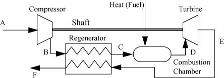
5.16. A Brayton gas turbine typically operates with only a small amount of fuel added so that the inlet temperatures of the turbine are kept relatively low because of material degradation at higher temperatures, thus the flowing streams can be modeled as only air. Refer to the online supplement for stream labels. Consider a Brayton cycle modeled with air under the following conditions: TA = 298 K, PA = PD = 0.1 MPa, PB = 0.6 MPa, and TC = 973 K. The efficiencies of the turbine and compressor are to be 85%. Consider air as an ideal gas stream with CP = 0.79·CP,N2 + 0.21·CP,O2. Determine the thermal efficiency, heat required, and net work output per mole of air assuming
a. The heat capacities are temperature-independent at the values at 298 K.
b. The heat capacities are given by the polynomials in Appendix E.
5.17. The thermal efficiency of a Brayton cycle can be increased by adding a regenerator as shown in the schematic below. Consider a Brayton cycle using air under the following conditions: TA = 298 K, PA = PE = PF = 0.1 MPa, PB = 0.6 MPa, TD = 973 K, TF = 563 K. The efficiency of the turbine and compressor are to be 85%. Consider air as an ideal gas stream with CP = 0.79·CP,N2 + 0.21·CP,O2, and assume the molar flows of B and E are equal. Determine the thermal efficiency, heat required, and net work output per mole of air, assuming
a. The heat capacities are temperature-independent at the values at 298 K.
b. The heat capacities are given by the polynomials in Appendix E.
5.18. Consider the air-standard Otto cycle explained in the online supplement. At the beginning of the compression stroke, P1 = 95 kPa, T1 = 298 K. Consider air as an ideal gas stream with CP = 0.79·CP,N2 + 0.21·CP,O2. If the compression ratio is 6, determine T2, T4, and the thermal efficiency, if T3 = 1200 K and the following are true
a. The heat capacities are temperature-independent at the values at 298 K.
b. The heat capacities are given by the polynomials in Appendix E.
5.19. A hexane (ρ ≈ 0.66 kg/L, μ = 3.2 E-3 g/(cm-s)) storage tank in the chemical plant tank farm is 250 m from the 200 L solvent tank that is to be filled in 3 min. A pump is located at the base of the storage tank at ground level. The storage tank is large enough so that the liquid height doesn’t change significantly when 200 L are removed. The bends and fittings in the pipe contribute lost work equivalent to 15 m of additional pipe. The pump and motor are to be sized based on a storage tank liquid level of 0.3 m above ground level to ensure adequate flow rate when the storage tank is nearly empty. Find the required power input to the pump and motor.
a. The pipe is to be 2.5 cm in diameter and the outlet is to be 10 m above ground level. The pump efficiency is 85%, the motor efficiency is 90%.
b. The pipe is to be 3.0 cm in diameter and the outlet is to be 8.5 m above ground level. The pump efficiency is 87%, the motor efficiency is 92%.
c. Determine the time required to fill the solvent tank using the pump and motor sized in part (a) if the storage tank liquid level is 6.5 m above ground.
d. Answer part (c) except determine the filling time for part (b).
5.20. Consider problem 5.16(a). Determine the amount of fuel required per mole of air if the fuel is modeled as isooctane and combustion is complete.
5.21. Consider problem 5.18(a). Determine the amount of fuel required per mole of air if the fuel is modeled as isooctane and combustion is complete.
5.22. In the event of an explosive combustion of vapor at atmospheric pressure, the vapor cloud can be modeled as adiabatic because the combustion occurs so rapidly. The vapor cloud expands rapidly due to the increase in moles due to combustion, but also due to the adiabatic temperature rise. Estimate the volume increase of a 22°C, 1 m3 mixture of propane and a stoichiometric quantity of air that burns explosively to completion. Estimate the temperature rise.
a. Derive the energy balance for a closed, constant-volume, adiabatic-system vapor phase chemical reaction, neglecting the energy of mixing for reactants and products, and assuming the ideal gas law.
b. Suppose that a 200 L propane tank is at 0.09 MPa pressure and, due to an air leak, contains the propane with a stoichiometric quantity of air. If a source of spark is present, the system will burn so rapidly that it may be considered adiabatic, and there will not be time for any flow out of the vessel. If ignited at 20°C, what pressure and temperature are generated assuming this is a constant volume system and the reaction goes to completion?