This chapter gives a quick tour of the smart card world. It introduces smart card basics as a foundation for exploring the rest of the book. For readers who want to learn more about smart card technology, two books, one by Rankl and Effing[1] and the other by Guthery and Jurgensen[2], are good resources. Readers who have a smart card background can skip or skim through this chapter.
Smart cards are often called chip cards, or integrated circuit (IC) cards. The integrated circuit incorporated in the credit card–sized plastic substrate contains elements used for data transmission, storage, and processing. A smart card may also have an embossed area on one face and a magnetic stripe on the other. Figure 2.1 illustrates the physical appearance of a smart card. The physical appearance and properties of a smart card are defined in ISO 7816, part 1. ISO 7816 is the document that sets the standard for the smart card industry.
Usually, a smart card does not contain a power supply, a display, or a keyboard. To communicate with the outside world, a smart card is placed in or near a card acceptance device, which is connected to a computer.
Smart cards fall into several groups. They can be divided into memory cards and microprocessor cards. Smart cards can also be categorized into contact cards and contactless cards based on the difference in the card access mechanism.
The earliest smart cards produced in large quantities were memory cards. Memory cards are not really smart, because they do not contain a microprocessor. They are embedded with a memory chip or a chip with memory and nonprogrammable logic.
Typically, memory cards hold up to 1K to 4K of data. They are used primarily as prepaid cards for public phones or other goods and services that are sold against prepayment.
Since a memory card does not have a CPU to process data, its data processing is performed by a simple circuit capable of executing a few preprogrammed instructions. Such a circuit has limited functions and cannot be reprogrammed. Therefore, memory cards cannot be reused. When the value in the card is spent, the card is disposed of.
Depending on the security requirements of the stored data, the data access can be protected by means of protected memory or secure logic. For example, prepaid phone cards can contain logic to prevent the value from being increased. However, memory cards can be counterfeited relatively easily.
The advantage of memory cards lies in the simple technology. Therefore, they are favored where low cost is a particular consideration.
By contrast, microprocessor cards, as the name implies, contain a processor. They offer greatly increased security and multifunctional capability. With a microprocessor card, data are never directly available to the external applications. The microprocessor controls data handling and memory access according to a given set of conditions (passwords, encryptions, and so on) and instructions from the external applications. Many current models of microprocessor cards feature built-in cryptographic support. Such cards are particularly useful for applications that need to address data security. Microprocessor cards are very flexible. They can be optimized for one application or can integrate several different applications. Their functionality is restricted only by the available memory resources and computing power.
Microprocessor cards are widely used for access control, banking applications, retail loyalty applications, wireless telecommunication, and so on, where data security and privacy are major concern.
As a result of mass production, the cost of microprocessor cards has fallen drastically since the early 1990s. Microprocessor cards typically cost between $1 and $20, depending primarily on the memory resources and the software functionality included in the card.
In general, the term smart card refers to both memory cards and microprocessor cards. However, some publications prefer to call only microprocessor cards smart cards, because of the intelligence provided by the embedded processor. The term chip cards is used for both memory cards and microprocessor cards.
Because a general-purpose programmable processor is required to support the Java Card environment, in this book the term smart card refers to microprocessor cards. Memory cards are not discussed further.
Contact cards must be inserted in a card acceptance device, and they communicate with the outside world by using the serial communication interface via eight contact points, as shown in Figure 2.1. Section 2.3.1 provides a detailed look at the contacts in a smart card.
Because a contact card must be inserted into a mechanical card acceptance device in the correct way and in an exact orientation, contactless smart cards are popular in situations requiring fast transactions. Public transport systems and access control for buildings are excellent applications for contactless cards.
Contactless cards do not need to be placed in a card acceptance device. They communicate with the outside world through an antenna wound into the card. Power can be provided by an internal battery or can be collected by the antenna. Contactless cards transmit data to a card acceptance device through electromagnetic fields.
Because the microcircuit of contactless cards is fully sealed inside the card, contactless cards overcome limitations of contact cards: there are no contacts to become worn from excessive use, cards do not need to be carefully inserted into a CAD, and cards do not have to be of a standard thickness to fit in a CAD card slot.
However, contactless cards have their own drawbacks. Contactless cards must be within a certain required distance to exchange data with the card acceptance device. As the card may move out of range very quickly, only limited data can be transmitted due to short duration of a transaction. It is possible for transactions to take place on a card or transmitted data to be intercepted without the card holder knowing it. Furthermore, contactless cards are currently more expensive than corresponding contact cards.
This book uses contact cards in the examples because they are more commonly used. Nevertheless, many discussions about contact cards apply equally well to contactless cards.
A smart card has contact points in the surface of the plastic substrate, an embedded central processing unit, and various kinds of memory. Some smart cards also come with coprocessors for math computation.
A smart card has eight contact points; their functional assignments are shown in
Figure 2.2. The dimensions and locations of the contacts are covered in part 2 of ISO 7816.
The Vcc point supplies power to the chip. Vcc voltage is 3 or 5 volts, with a maximum deviation of 10 percent. Smart cards in mobile phones typically have the 3-volt Vcc range.
The RST point is used for sending the signal to reset the microprocessor—this is called a warm reset. A cold reset is done by switching the power supply voltage off and on again. Taking the card out of the CAD and reinserting it results in a cold reset.
Smart card processors do not possess internal clock generation. The CLK point supplies the external clock signal from which the internal clock is derived.
The GND point is used as a reference voltage; its value is considered to be zero volts.
The Vpp point is optional and is used only in older cards. When used, it supplies the programming voltage with two levels. The lower voltage is called the idle state; it must be maintained by the CAD until the other voltage level (active state) is required. The voltage change is necessary to program EEPROM memory in some old smart card chips.
The I/O point is used to transfer data and commands between the smart card and the outside world in half-duplex mode. Half duplex means that commands or data can be transmitted in only one direction at any particular time.
The RFU points are reserved for future use.
The central processing unit in most current smart card chips is an 8-bit microcontroller, usually using the Motorola 6805 or Intel 8051 instruction set, and with clock speeds up to 5MHz. High-end cards very often include a clock multiplier (by 2, 4, or 8), which allows these cards to operate up to 40MHz (5MHz times 8).
Newer smart card chips have a 16-bit or 32-bit microcontroller, and smart cards with reduced instruction set (RISC) architecture are also available. In the future, 16-bit and 32-bit smart cards will likely become more common.
Smart card chips that are designed for use in security applications very often have a built-in coprocessor. A cryptographic coprocessor is a special integrated circuit for expediting calculations, particularly modular arithmetic and large-integer calculations. Such calculations are required by cryptographic operations, such as the RSA algorithm.
The inclusion of a coprocessor usually affects the cost of the chip.
Smart cards usually contain three kinds of memory: persistent nonmutable memory, persistent mutable memory, and nonpersistent mutable memory. ROM, EEPROM, and RAM are the most widely used memories, respectively, for the three kinds
ROM (read-only memory) is used for storing the fixed program of the card. No power is needed to hold data in this kind of memory. However, as the name implies, it cannot be written to after the card is manufactured. A smart card's ROM contains operating system routines as well as permanent data and user applications. The process of writing a binary image (representing programs and data) into the ROM is called masking. It occurs during the chip fabrication process.
EEPROM (electrical erasable programmable read-only memory), like ROM, can preserve data content when power to the memory is turned off. The difference is that the content in this kind of memory can actually be modified during normal use of the card. Therefore, it is used for data storage—the smart card's equivalent of the hard disk on a PC. User applications can also be written into EEPROM after the card is made. The important electrical parameters of EEPROM are the number of write cycles over the lifetime of a card, data retention period, and access time. EEPROM in most smart cards can reliably accept at least 100,000 write cycles and can retain data for 10 years. Reading from EEPROM is as fast as reading from RAM, but writing to EEPROM is 1,000 times slower than writing to RAM.
RAM (random access memory) is used as temporary working space for storing and modifying data. RAM is nonpersistent memory; that is, the information content is not preserved when power is removed from the memory cell. RAM can be accessed an unlimited number of times, and none of the restrictions found with EEPROM apply.
ROM is the least expensive of these three kinds of memory. EEPROM is more expensive than ROM because an EEPROM cell takes up four times as much space as a ROM cell. RAM is very scarce in a smart card chip. A RAM cell tends to be approximately four times larger than an EEPROM cell.
Today, other memory technologies are also gaining popularity in smart cards. For example, flash memory is becoming more common. Flash memory is a kind of persistent mutable memory; it is more efficient in space and power than EEPROM. Flash memory can be read bit by bit but can be updated only as a block. Thus, flash memory is typically used for storing additional programs or large chunks of data that are updated as wholes.
A smart card is inserted into a card acceptance device (CAD), which may connect to another computer. Card acceptance devices can be classified as two types: readers and terminals.
A reader is connected to the serial, parallel, or USB port of a computer, through which a smart card communicates. A reader has a slot into which a card is placed, or it can receive data carried through electromagnetic fields from a contactless card. In addition to supplying the card with power, a reader establishes a data communication pathway in which the smart card can talk to the computer connected to the reader. Though normally readers do not have the intelligence to process data, many have error detection and correction functions if transmitted data are not compliant with the underlying transport protocol.
Terminals, on the other hand, are computers on their own. A terminal integrates a smart card reader as one of its components. The most commonly seen terminals are devices used in gas stations and stores for payments and credit card transactions. Bank ATMs are another form of terminal. In addition to having the functionality of a smart card reader, a terminal has the ability to process data exchanged between itself and the smart card. For example, an ATM, if it accepts smart cards, can add or deduct money from an electronic purse application in the smart card.
For simplicity, this book does not draw the line between a reader and a terminal; they are both referred to as card acceptance devices, or CADs. The applications that communicate with the smart card—whether they reside in the computer connected to the reader or in the terminal—are called host applications. Host applications direct the process of communication with the smart card, as explained in Section 2.4.2.
The communication pathway between the card and the host is half-duplexed; that is, the data can either be sent from the host to the card or from the card to the host but not both at the same time.
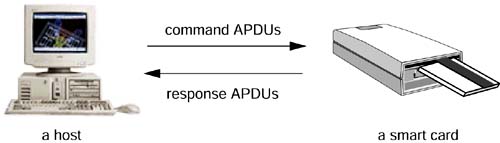
When two computers communicate with each other, they exchange data packets, which are constructed following a protocol, such as TCP/IP. Similarly, smart cards speak to other computers by using their own data packets—called APDUs (application protocol data units). An APDU contains either a command or a response message.
In the card world, the master-slave model is employed. A smart card always plays the passive (slave) role, waiting for a command APDU from a host. It then executes the instruction specified in the command and replies to the host with a response APDU. Command APDUs and response APDUs are exchanged alternately between a card and a host, as shown in Figure 2.3.
The APDU protocol, as specified in ISO 7816-4, is an application-level protocol between a smart card and a host application. APDU messages under ISO 7816-4 comprise two structures: one used by the host application at the CAD side of the channel to send commands to the card, the other used by the card to send responses back to the host application. The former is referred to as the command APDU (C-APDU) and the latter as the response APDU (R-APDU). A command APDU is always paired with a response APDU. Their structures are illustrated in Table 2.1 and Table 2.2, respectively.
The command APDU header consists of 4 bytes: CLA (class of instruction), INS (instruction code), and P1 and P2 (parameters 1 and 2). The class byte identifies a category of command and response APDUs. The instruction byte specifies the instruction of the command. The two parameter bytes P1 and P2 are used to provide further qualifications to the instruction.
The section after the header in a command APDU is an optional body that varies in length. The Lc field in the body specifies the length of the data field (in bytes). The data field contains data that are sent to the card for executing the instruction specified in the APDU header. The last byte in the command APDU body is the Le field, which specifies the number of bytes expected by the host in the card's response.
The response APDU, sent by the card in reply to a command APDU, consists of an optional body and a mandatory trailer. The body consists of the data field, whose length is determined by the Le field in the corresponding command APDU. The trailer consists of two fields SW1 and SW2, together called the status word, denoting the processing state in the card after executing the command APDU. For example, the status word “0x9000” means that a command was executed successfully and completely.
The data field is optional in both command and response APDUs. Therefore, APDUs can be further categorized as having the following four cases, based on whether a data field is contained in the C-APDU or R-APDU (Figure 2.4).
In case 1, no data are transferred to or from the card, so the command APDU contains only the header, and the response APDU contains only the trailer status word.
In case 2, no data are transferred to the card, but data are returned from the card. The body of the command APDU contains one byte—the Le field, which specifies the number of data bytes in the corresponding response APDU.
In case 3, data are transferred to the card, but no data are returned from the card as a result of processing the command. The body of the command APDU includes the Lc field and the data field. The Lc byte specifies the length of the data field. The response APDU contains only the trailer status word.
In case 4, data are transferred to the card, and data are returned from the card as a result of processing the command. The body of the command APDU includes the Lc field, the data field, and the Le field. The response APDU contains both the data and the trailer status word.
APDUs are transmitted by the next-level protocol—the transport protocol, defined in ISO 7816-3. The data structures exchanged by a host and a card using the transport protocol are called transmission protocol data units, or TPDUs.
The two transport protocols that are in primary use in smart card systems today are the T=0 protocol and the T=1 protocol. The T=0 protocol is byte-oriented, which means that the smallest unit processed and transmitted by the protocol is a single byte. By contrast, the T=1 protocol is block-oriented; in other words, a block, consisting of a sequence of bytes, is the smallest data unit that can be transmitted between a card and a host.
The TPDU structures used in the T=0 protocol are quite different from those used in the T=1 protocol. For more information of the transport protocol, see ISO 7816-3.
Immediately after it is powered up, a smart card sends out an answer to reset (ATR) message to the host. This conveys to the host the parameters required by the card for establishing a data communication pathway. The ATR is up to 33 bytes. It contains transmission parameters, such as the transport protocol supported by the card (usually the T=0 or the T=1); the data transmission rate; card hardware parameters, such as the chip serial number and the mask version number; and other information that the host needs to know about the card.
The smart card operating systems have little resemblance to desktop operating systems, such as UNIX, Microsoft Windows, or even DOS. Rather, smart card operating systems support a collection of instructions on which user applications can be built. ISO 7816-4 standardizes a wide range of instructions in the format of APDUs. A smart card operating system may support some or all of these APDUs as well as the manufacturer's additions and extensions.
Most smart card operating systems support a modest file system based on ISO 7816-4. ISO 7816-4 APDUs are largely file system–oriented commands, such as file selection and file access commands. In this case, a user application often is a data file that stores application-specific information. The semantics and instructions to access the application data file are implemented by the operating system. Therefore, the separation between the operating system and the applications is not very well defined.
These file system–centric operating systems are well established in smart cards that are available today. However, newer operating systems, which support a better system-layer separation and downloading of custom application code, are becoming more and more popular. Java Card technology is one technology in this new trend.[1]
Smart cards defined in ISO 7816-4 can have a hierarchical file system structure, as shown in Figure 2.5. The ISO 7816-4 file system supports three types of files: master file (MF), dedicated file (DF), and elementary file (EF). Each file is specified by either a 2-byte identifier or a symbolic name up to 16 bytes.
Before any other operations on a file can be performed, the file must be selected. (This is equivalent to opening a file in a modern operating system.) Some cards automatically select the master file when the card is powered on. Access to files is controlled by access conditions, which can be specified differently for read and for write access.
The master file (MF) is the root of the file system. The MF can contain dedicated files and elementary files. There is only one MF in a smart card.
A DF is a smart card directory file that holds other dedicated files and elementary files. A master file is a special type of DF.
An elementary file is a data file; it cannot contain other files. Based on the file structure, there are four types of elementary files (Figure 2.6). A transparent file is structured as a sequence of data bytes, whereas the other three EF types are structured as a sequence of individually identifiable records. A linear fixed file has records of fixed size; a linear variable file has records of variable size; and a cyclic file has fixed records organized as a ring.
In a cyclic file, records are in the reverse order to the order in which they were inserted into the file—the last inserted record is identified as record 1. Once the file is full, the next write instruction overwrites the oldest record in the file, and it becomes the new record 1.
Smart card systems are distributed systems that consist of two parts: the host system residing in the computer connected to the reader or in the terminal and the card system inside a smart card.
Most smart card software, including system software and user application software, runs on the host side. The system software recognizes a specific smart card and handles communication between the user application and the card. The system software also provides support to the smart card infrastructure, such as card management (issuance and operations), security, and key management. User applications implement functions that work with a specific card or an application on the card. A simple user application is the one that supports and handles a set of APDUs exchanged with the card, but many user applications have a rich function set. For example, an ATM application provides user authentication, transaction processing, and a friendly user interface for easy access. Host software is usually written in high-level programming languages, such as Java, C, C++, and so on.
Card software is the software that runs on the smart card itself. It too includes system software and user application software. The system software typically includes the operating system and utilities that control memory management, handle I/O communication with the host, ensure data integrity and security, support the ISO file system (if implemented), and provide system utilities to the card applications. Card applications contain data and support functions that operate on data. For example, a purse application contains a balance and implements functions to update the balance. However, in traditional smart cards, instructions supported in the system are often sufficient for applications. In this case, the special application software is not required. Card software can be implemented either in the assembly language of the card microprocessor or in a high-level programming language that can be interpreted by the microprocessor.
Smart card systems are developed by implementing and integrating card software and host software. This involves cooperations between providers of card operating systems, vendors of card terminals, application developers (both card side and host side), and card issuers. These parties are often not from the same companies. To ensure interoperability, industry initiatives, such as the Open Platform and the OpenCard Framework, offer an integrated environment for the development and operation of smart card systems so that software components from various vendors can work together.
Java Card technology provides a ubiquitous platform in which card-side applications can be written in Java and can run on any smart card that supports the Java Card runtime environment.
During the past 15 years, a number of smart card standards and specifications have been defined to ensure that smart cards, card acceptance devices, and applications developed and manufactured by different vendors can work together. This section lists some well-known standards and specifications for developing smart card systems.
ISO 7816 “Identification cards—Integrated circuit cards with contacts,” published by the International Organization for Standardization (ISO), is the most important standard defining the characteristics of chip cards that have electrical contacts[6]. ISO 7816 covers various aspects of smart cards:
Part 1—physical characteristics
Part 2—dimensions and location of the contacts
Part 3—electronic signals and transmission protocols
Part 4—interindustry commands for interchange
Part 5—application identifiers
Part 6—interindustry data elements
Part 7—interindustry commands for SCQL
The European Telecommunications Standards Institute (ETSI) has published a set of standards that cover smart cards for use in public and cellular telephone systems[8]. The Global System for Mobile Communications (GSM) defined by ETSI is a specification for an international terrestrial mobile telephone system. Originally intended to cover a few countries in central Europe, it is increasingly developing into an international standard for mobile telephones. There are several GSM standards, in particular:
GSM 11.11—specification of the SIM–mobile equipment interface.
GSM 11.14—specification of the SIM application toolkit for the SIM–mobile equipment interface.
GSM 03.48—security mechanisms for the SIM application toolkit.
GSM 03.19—SIM API (Application Programming Interface) for the Java Card platform. This standard, based on GSM 11.11 and GSM 11.14, defines Java API for developing GSM applications that run on the Java Card platform. The API is an extension to the Java Card 2.1 API.
The EMV specification, defined by Europay, MasterCard, and Visa, is based on the ISO 7816 series of standards with additional proprietary features to meet the specific needs of the financial industry. The latest version of the specifications, EMV 96 version 3.1.1, was published in May 1998 and comes in three parts:
EMV '96 Integrated Circuit Card Specification
EMV '96 Integrated Circuit Card Terminal Specification
EMV '96 Integrated Circuit Card Application Specification
The Open Platform (OP) defines an integrated environment for the development and operation of multiple-application smart card systems[9]. The Open Platform consists of a card specification and a terminal specification. The card specification defines the cross-industry, nonproduct-specific requirements to implement an Open Platform card. It defines the off-card communication with the terminal and the on-card application management. The terminal specification defines the part of the application architecture within the terminal. It further defines the terminal to be ISO and EMV compatible.
The Open Platform specifications were initially developed by Visa and now have been transferred to GlobalPlatform, an organization to promote a global infrastructure for smart card implementation across multiple industries.
The OpenCard Framework (OCF) was initially produced by IBM and is currently owned and developed by the OpenCard consortium, which includes major players in the smart card industry[5]. OCF is the host-side application framework providing a standard interface for interacting with card readers and applications in the card. The architecture of OCF is a structured model that divides functions among card terminal vendors, card operating system providers, and card issuers. The goal is to reduce dependence on each of these parties as well as dependence on the platform providers.
OCF is designed with the use of a smart card in a network computer in mind, and thus is implemented in the Java programming language.
PC/SC specifications (Interoperability Specification for ICCs and Personal Computer Systems) are owned and defined by the PC/SC Workgroup, an industry consortium with major players in the smart card industry[7]. PC/SC defines a general-purpose architecture for using smart cards on personal computer systems.
In the PC/SC architecture, host-side smart card applications are built on top of one or more service providers and a resource manager. A service provider encapsulates functionality exposed by a specific smart card and makes it accessible through high-level programming interfaces. A resource manager manages the smart card–relevant resources within the system for accessing to card acceptance devices and, through them, individual smart cards.
PC/SC and OCF have many similar concepts. When running on a Windows platform, OCF can access card acceptance devices through the installed PC/SC resource manager.
[1] Java Card technology does not provide core APIs for the ISO file system. Most of the common-use cases of the ISO file system in applications could be achieved in the Java programming language by encapsulating files as arrays or objects. The Java Card 2.1 API reference implementation sample application JavaPurse (which can be downloaded at http://java.sun.com/products/javacard/) shows an example of implementing ISO 7816–compliant files and supporting ISO 7816-4 file system–oriented APDUs.