
CHAPTER 11
SnapShotBot—Build It
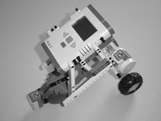
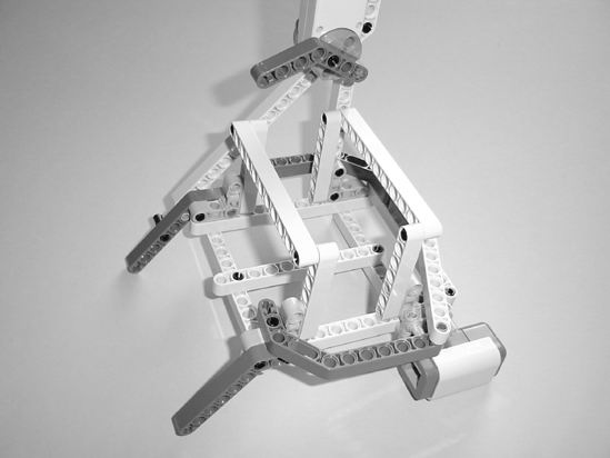
Go ahead and take a look at one version of the SnapShotBot in Figure 11-1. It's a weird-looking little bot, but, then again, I like strange-looking robots . . . and this one definitely qualifies. As you can see, the Light Sensor is located at the front. I've also placed the camera towards the back of the bot at an angle. The weight of the Brick is sufficient to keep the bot from tipping over, thankfully.
There are a few other items that you might be interested in, as well. I've used one of the plastic balls that come with the basic Lego Mindstorms NXT kit as the front wheel. You'll see this trick used on a lot of NXT bots because the ball-wheel rolls easily and allows bots to turn a little more smoothly than does a rubber wheel. I could have used something similar to the pivot wheel found on the ExploroBot, but I wanted to try this option out. You'll also notice during the building process that I use a lot of the longer beams (11 and 15 holes) to provide reinforcement and strength to the camera housing. Since the housing is angled back and is a little top-heavy, I rely on these types of support beams a lot—it's a personal building style that works for me.
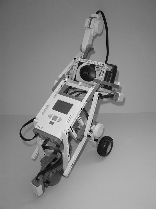
Figure 11-1. One possible version of a SnapShotBot
Jump In
I had no trouble getting my basic design for the SnapShotBot. Using my sketches from Chapter 10, I knew that I wanted my bot to have two rear-wheels to drive this heavier bot. I intentionally placed the camera at the top of the bot because I wanted it to have the best view (even with the angle) to take a picture.
One special note here: I purchased a disposable camera for this bot, but I could just have easily built the camera cage (that's what I'm calling it, okay?) to hold my digital camera. It wouldn't have been as wide, but it would definitely have been taller to keep the digital camera from falling out. You may have to play around with the camera cage a bit to get it to fit the camera you decide to use. Keep the camera nearby as you build so you don't have to guess about the dimensions of the cage. A few extra pieces here and there will allow the bot to hold your camera firmly.
If I later decide to use my digital camera, I can reprogram the bot to take numerous photos. If I were to send my bot into an unknown area with the risk that it might not come back, I'd probably rather use a disposable camera so I wouldn't lose my expensive digital one. But for now, all I need my bot to do is go in and take one photo.
Follow along with my instructions to build my version or build your own version and feel free to compare your design to mine—you may find an idea or two that you can use with your own bot.
Note I really would like to see your version of the SnapShotBot, so take a picture and e-mail it to me. My e-mail address is in the Introduction.
Okay, let's go build the SnapShotBot!
Step by Step
I've divided the SnapShotBot building instructions into three sections. The first section contains the basic body—the Intelligent Brick and two wheel motors. The second section adds the ball-wheel assembly, the Light Sensor, and reinforcement beams. The third section completes the SnapShotBot by adding the camera cage, one motor to push the camera's button, and more reinforcement beams. Build these three sections and wire them up, and your SnapShotBot will be complete and ready for programming.
As with previous chapters, I'll add comments to sections where a little help might be needed. And remember, if you see an image with text and arrows, pay attention because the text and arrows are probably pointing to a placement of a part (or parts) that otherwise might not be immediately noticeable in the picture.
And, finally, I'll add new parts to an image to let you know what parts are needed in an upcoming step.
First Section: Basic Body
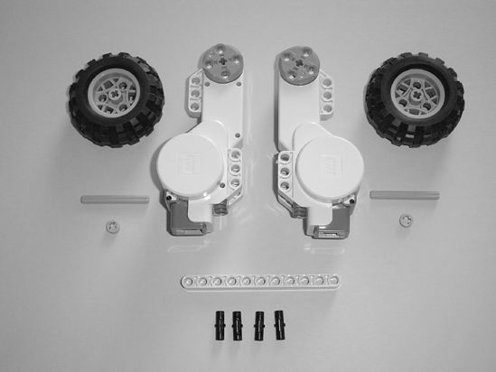
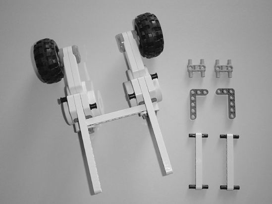
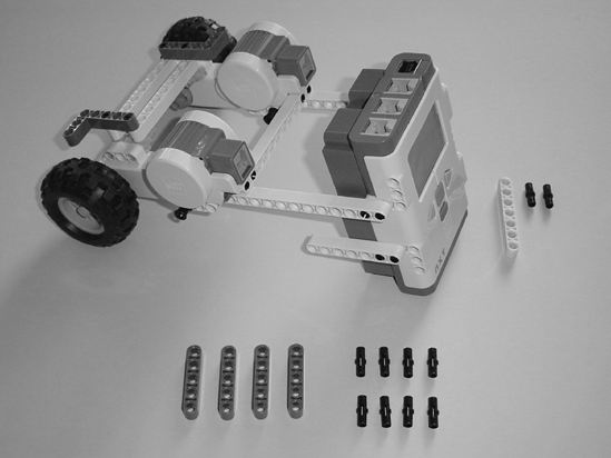
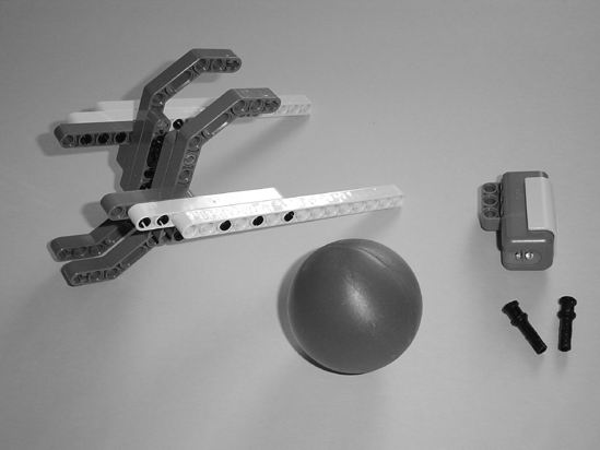
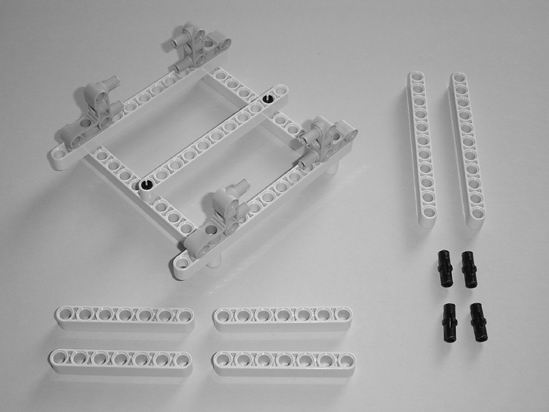
Figures 11-2 through 11-16 show the steps and components used to build the basic body and wheels, as well as a few pieces needed before you begin the second section to add the ball-wheel assembly and Light Sensor. Start with the pieces you see in Figure 11-2.
 |
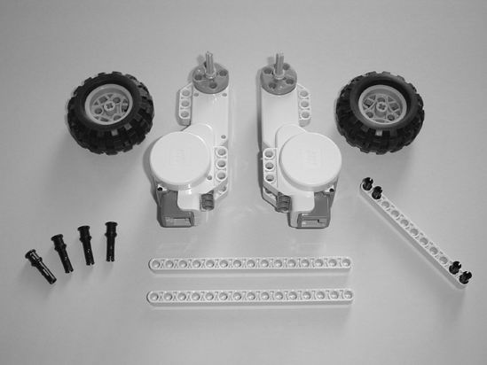 |
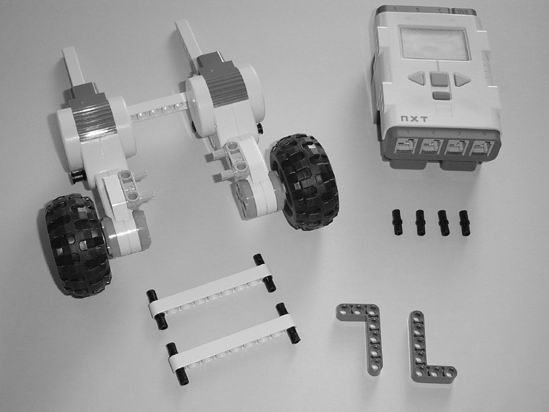
| Figure 11-2. Starting pieces for the SnapShotBot | Figure 11-3. Place the axle rods with half-bushings in the motors and insert the four small black connectors in the 11-hole beam as shown. |
 |
 |
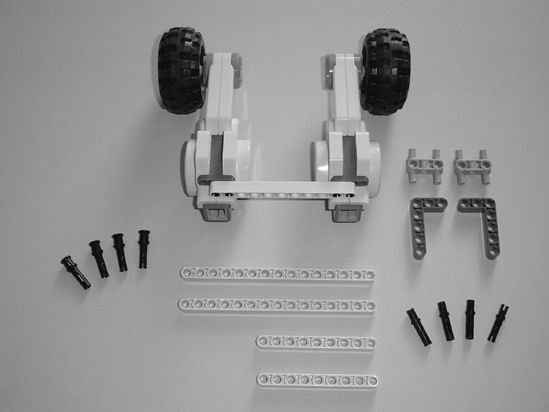
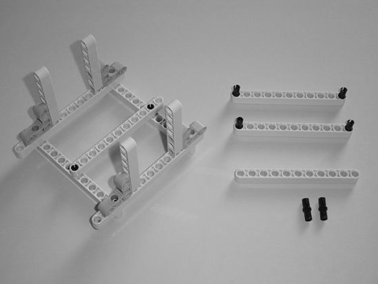
| Figure 11-4. Connect the two motors with the 11-hole beam. | Figure 11-5. Use two pins to connect a 15-hole beam to each motor as shown. |
 |
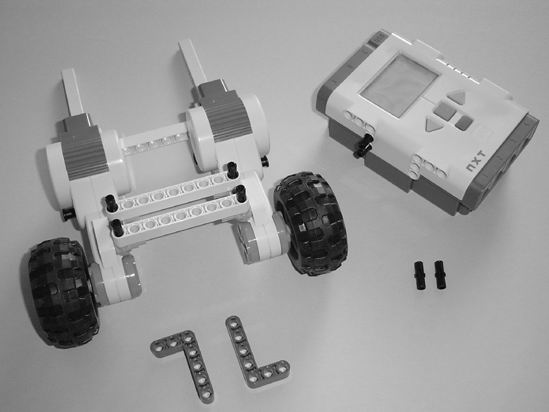 |
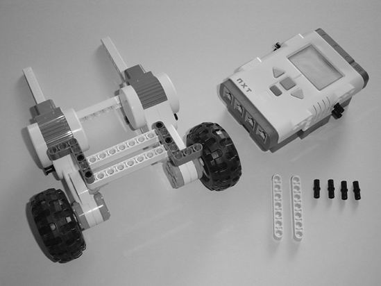
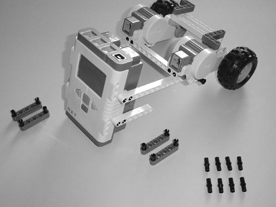
| Figure 11-6. Flip the Brick over and insert the two gray components into the motors as shown. | Figure 11-7. Use the two 9-hole beams to reinforce the connection between the motors, and put two small black connectors in the side of the Brick as shown. |
 |
 |
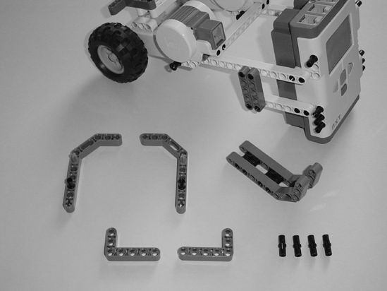
| Figure 11-8. Put two more small black connectors in the Brick as shown and place the two L-shaped components. | Figure 11-9. Connect the motor assembly to the Brick and then connect one of the 7-hole beams using two small black connectors. |
Note These two L-shaped components are where I will tie the two pieces of twine.
 |
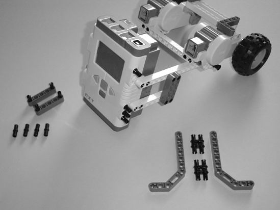 |
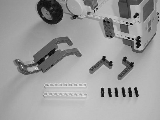
| Figure 11-10. Flip the Brick to the other side and connect the other 7-hole beam using two small black connectors. | Figure 11-11. Use the two gray 5-hole beams to reinforce the legs, and place the four small black connectors in the Brick as shown. |
 |
 |
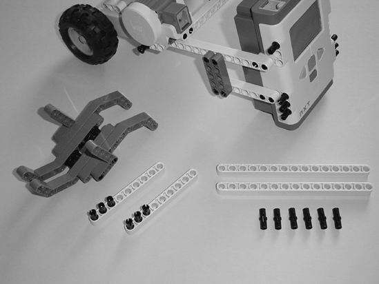
| Figure 11-12. Flip the Brick to the other side and reinforce the legs using the other two gray 5-hole beams, and place the other four small black connectors. | Figure 11-13. Assemble the gray components—pay attention to the position of the small blue connectors and the small black connectors. |
 |
 |
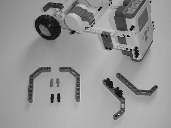
| Figure 11-14. Connect the gray components and place two small black connectors in each L-shaped component. | Figure 11-15. Place the L-shaped component and three small black connectors in each 9-hole beam. |
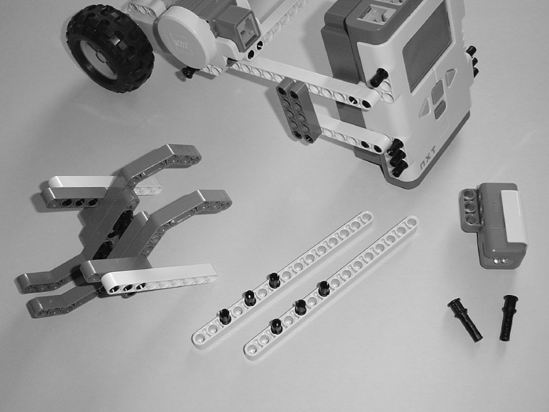
Figure 11-16. Connect the 9-hole beams as shown and place three small black connectors in each 15-hole beam.
Now it's time for the ball-wheel assembly and Light Sensor . . .
Second Section: Ball-Wheel Assembly and Light Sensor
Figures 11-17 through 11-28 show you how to complete the main body. When finished, you'll have a fully functional rolling bot body that could be customized with other parts and sensors to perform other duties. Okay, let's move forward.
 |
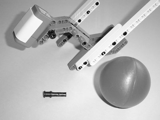 |
| Figure 11-17. Start with a plastic ball, the Light Sensor, and the assembly shown. | Figure 11-18. Connect the Light Sensor using one of the black pins as shown. Notice the rear hole on the Light Sensor is visible and the pin does not go through it. |
 |
 |
| Figure 11-19. On the other side of the assembly, use the other black pin to connect the Light Sensor. | Figure 11-20. Connect the ball-wheel assembly to the Brick as shown. It will swivel for now, and that's okay. |
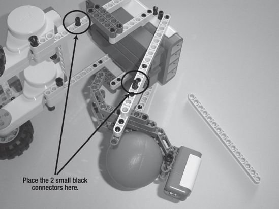
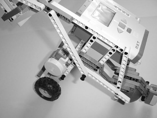
Figure 11-21. Place the two small black connectors as shown.
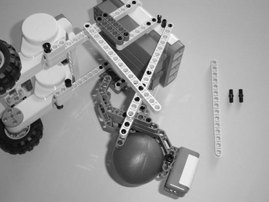
Figure 11-22. Use the 15-hole beam to reinforce the ball-wheel assembly.
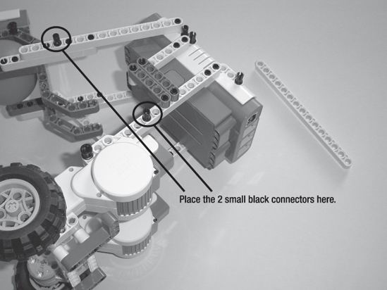
Figure 11-23. Turn the Brick over and place the two small black connectors as shown.
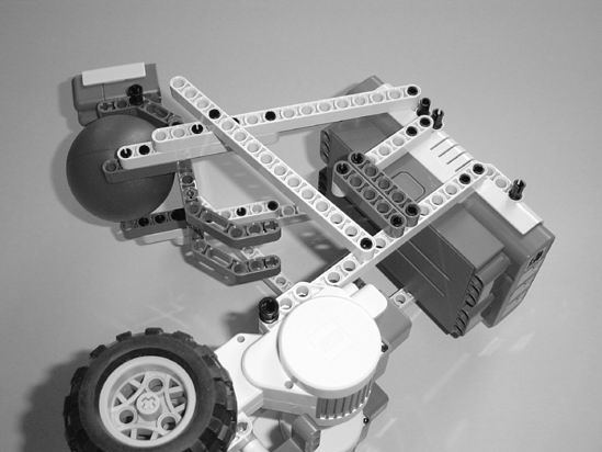
Figure 11-24. Use the 15-hole beam to reinforce the ball-wheel assembly.
 |
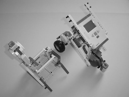
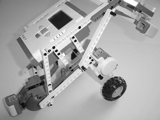
 |
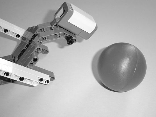
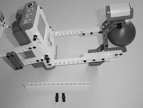
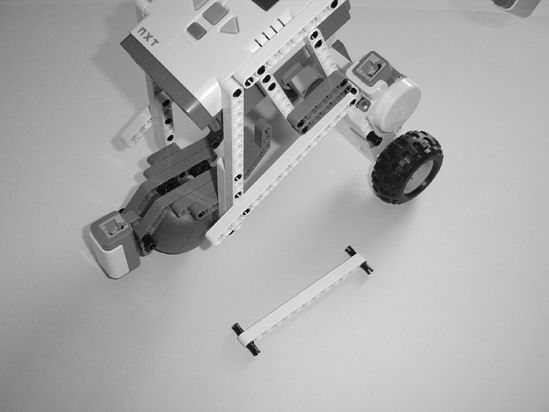
| Figure 11-25. The rolling main body so far | Figure 11-26. These 15-hole beams will hold the camera cage. |
 |
 |
| Figure 11-27. Connect the small black connectors as shown. | Figure 11-28. Place the 15-hole beams on the side of the Brick. |
At this point, you have a three-wheel rolling bot. There are plenty of places to connect other motors, parts, and sensors to customize this bot. But we need to finish the SnapShotBot, so let's move on to the camera cage and motor.
Third Section: Camera Cage and Motor
We're almost finished. We need to assemble the camera cage and design a method for pushing the camera's button. Figures 11-29 through 11-61 cover the completion of this bot.
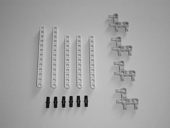
Figure 11-29 shows the pieces needed to start building the camera cage.
 |
 |
| Figure 11-29. Start with these components for the camera cage. | Figure 11-30. Place the small black connectors as shown. |
 |
 |
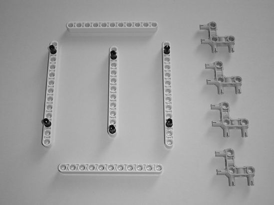
| Figure 11-31. Connect the 11-hole beam to the other 11-hole beams as shown. | Figure 11-32. Place the two 13-hole beams as shown. |
 |
 |
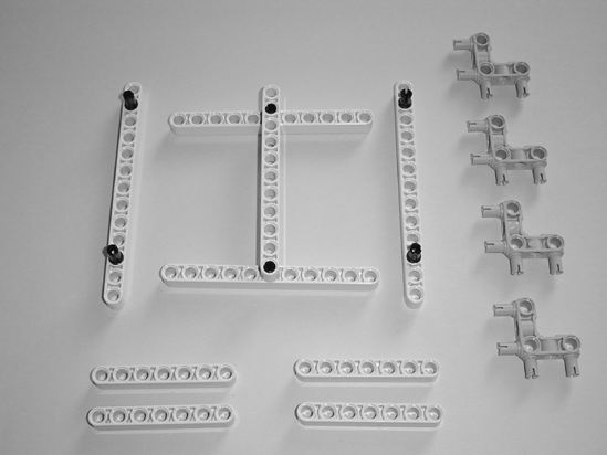
| Figure 11-33. Connect the four gray pins to the camera cage body. | Figure 11-34. Connect the four 7-hole beams to the gray pins and place two small black black connectors in the 11-hole beams. |
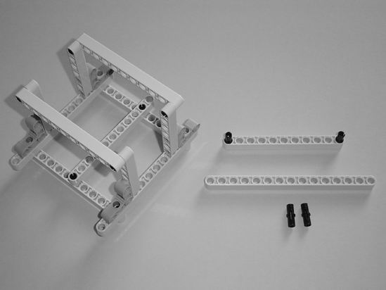
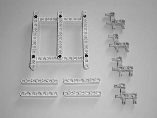
Figure 11-35. Connect the two 11-hole beams to the 7-hole beams on the camera cage body and place two small black connectors in the other 11-hole beam.
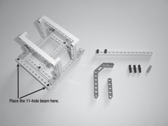
Figure 11-36. Place the 11-hole beam on the cage and two small black connectors in the 15-hole beam.
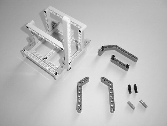
Figure 11-37. Connect the 15-hole beam to the cage to hold the motor.
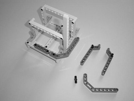
Figure 11-38. Connect the two gray components to the cage as shown.
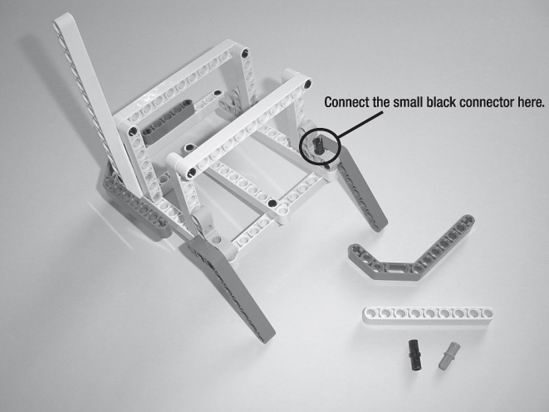
Figure 11-39. Spin the cage around and connect the two gray legs. Also place the small black connector as shown.
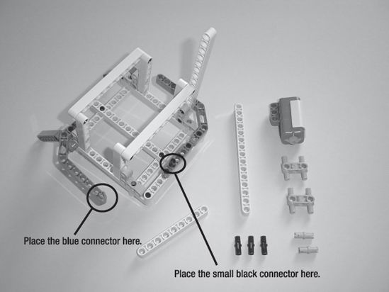
Figure 11-40. Connect the gray component. Place the blue connector and the small black connector as shown.
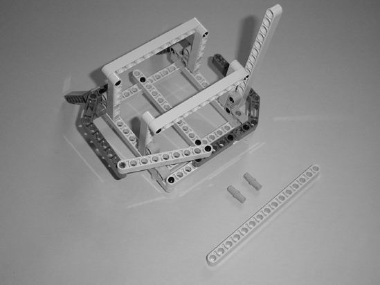
Figure 11-41. Connect the 9-hole beam.
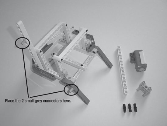
Figure 11-42. Spin the cage around and place the two small gray connectors as shown.
 |
 |
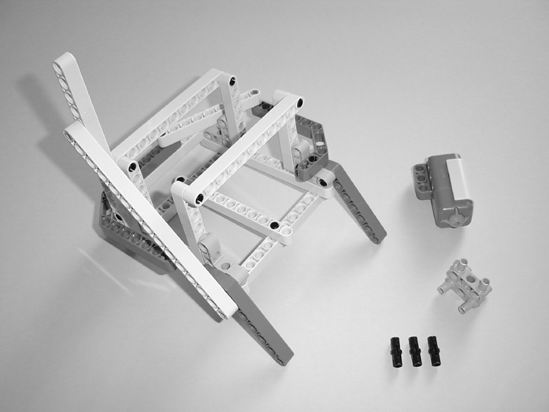
| Figure 11-43. Connect the 15-hole beam to the cage and snap the two small gray pins together. | Figure 11-44. Connect the two small gray pins to the Sound Sensor. |
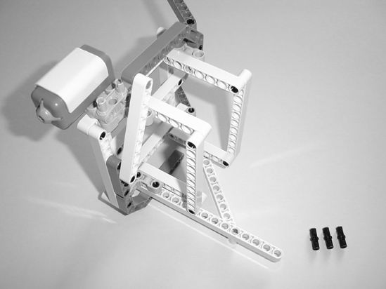
Figure 11-45. Tip the cage on its side as shown and connect the Sound Sensor.
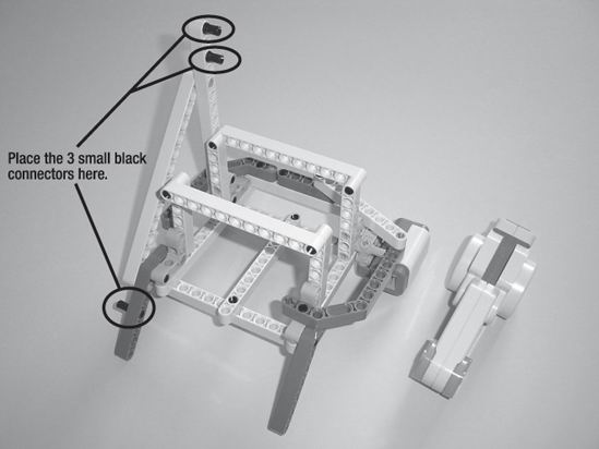
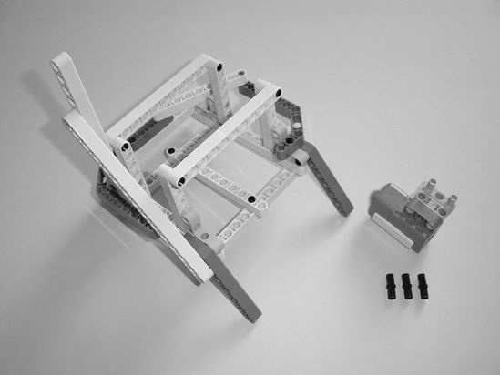
Figure 11-46. Place the three small black connectors.
 |
 |
| Figure 11-47. Connect the motor to the 15-hole beam as shown. | Figure 11-48. Place the blue connector and small black connector in the gray component. |
 |
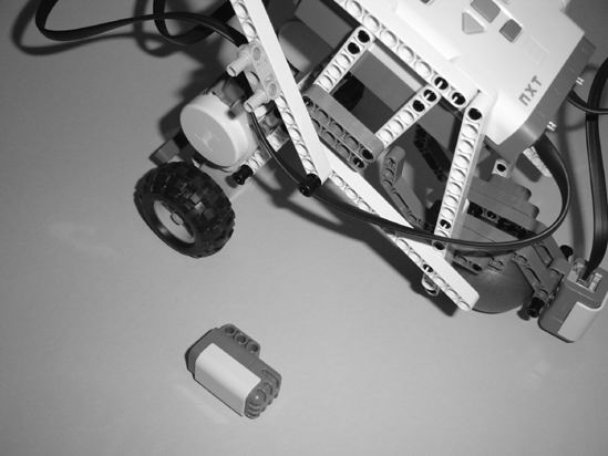
 |
| Figure 11-49. Connect the gray component to the motor as shown. This is the arm that will press on the camera button. | Figure 11-50. Retrieve the main body so you can connect to the camera cage. |
 |
 |
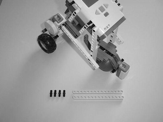
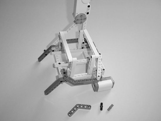
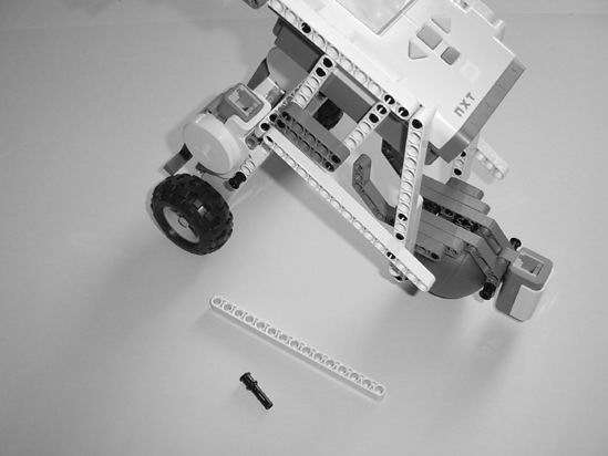
| Figure 11-51. Connect the camera cage assembly to the main body as shown. | Figure 11-52. A 13-hole beam and two long black connectors will be used for reinforcement. |
 |
 |
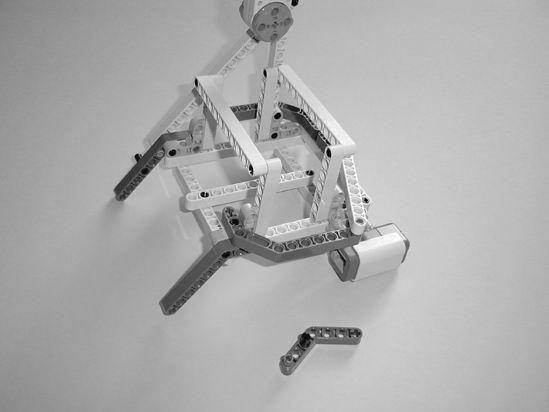
| Figure 11-53. Place the two long black connectors in the 13-hole beam as shown. | Figure 11-54. Connect the 13-hole beam to the main body. |
 |
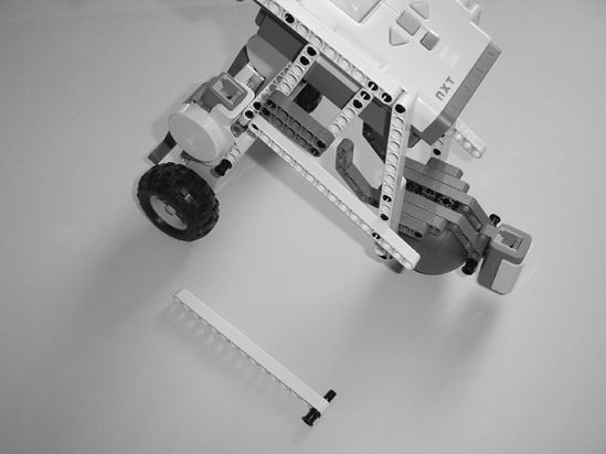 |
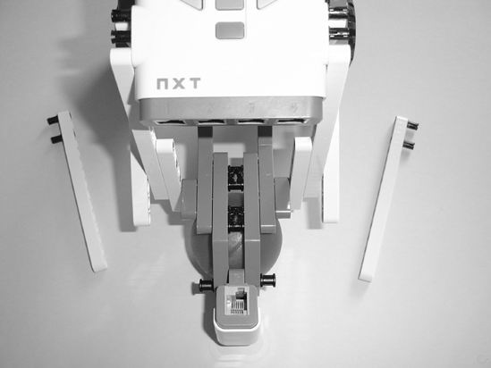
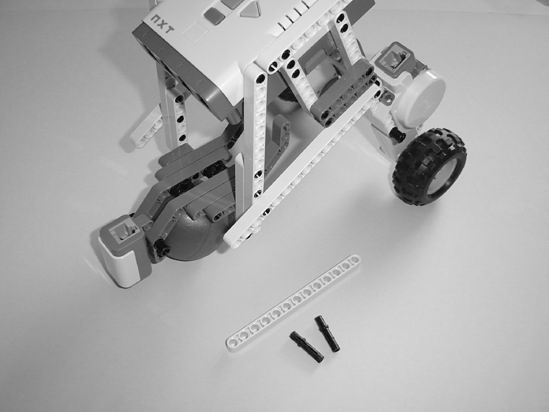
| Figure 11-55. A 15-hole beam and a black pin are used for reinforcement on the other side. | Figure 11-56. Insert the black pin in the 15-hole beam as shown. |
 |
 |
| Figure 11-57. Connect the 15-hole beam to the main body. | Figure 11-58. The Sound Sensor and gray component will be needed. |
 |
 |
| Figure 11-59. Place the gray component as shown. | Figure 11-60. Connect the Sound Sensor to the bot. |
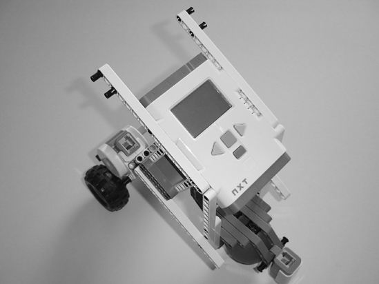
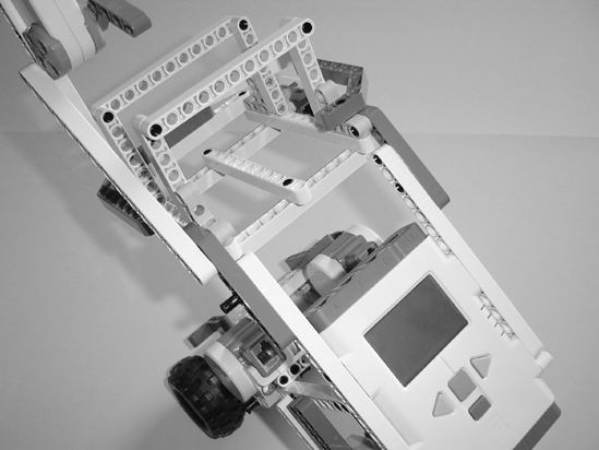
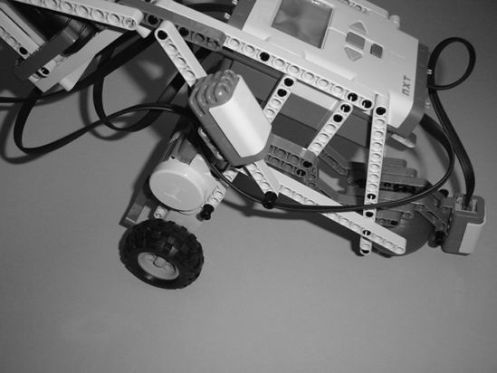
Now, put your camera in the camera cage and position the arm that will press the button so that it is directly over the button, but not pressing down on it. In Figure 11-61 you can see that I've got the small arm almost touching the camera button.
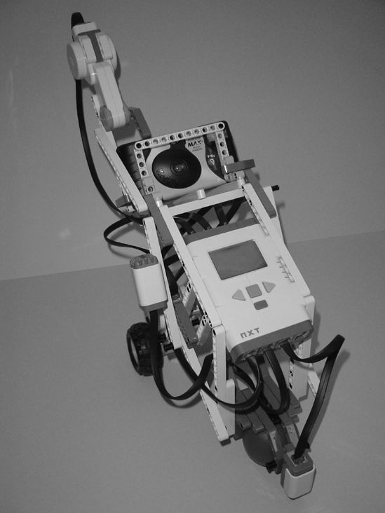
Figure 11-61. The unwired SnapShotBot completed
All that's left to do is wire it up and program it. Take another look at Figure 11-1 to see how I've wired up the bot. Now that you've completed your SnapShotBot, it's time to program it. Chapter 12 will walk you through the steps to program your little (or not-so-little) SnapShotBot so that it can enter the library, take a picture, circle around the basket, and let your team retrieve the key.