
CHAPTER 15
GrabberBot—Build It
The final design of my GrabberBot has a lot of potential modifications. I realized after I completed the design that if I removed the Ultrasonic Sensor and the upper beams, I would be left with a nice base unit that could be used in future designs. But that's not what this chapter is about. This chapter gives you the building instructions for constructing a bot that can move down the tunnel and successfully retrieve the scroll.
If you've built your own version of the GrabberBot, congratulations. How does it compare to my design (see Figure 15-1)? I hope you're beginning to see that there are an unlimited number of designs for successful completion of these challenges. The only limits are your imagination and the parts in your kit.
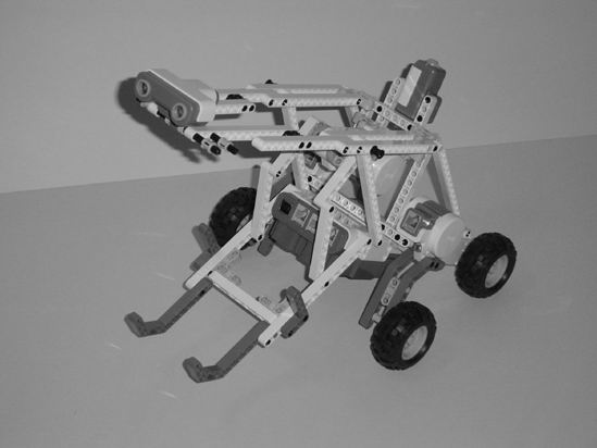
Figure 15-1. One version of a GrabberBot
Note E-mail me a picture of your version of the GrabberBot—I'd love to see it. You can find my e-mail in the Introduction at the start of the book.
Now, on to the GrabberBot's building instructions.
The GrabberBot's building instructions are divided into three sections. The first section consists of the main body (Brick, three motors, four wheels). The second section adds the lifting arm mechanism, and the third section adds the Ultrasonic Sensor, Touch Sensor, and various support beams. After you've built the GrabberBot, Chapter 16 will provide you with the programming instructions.
Just like previous building instruction chapters, comments will be provided for sections that might be a little tricky. Some images will include text and arrows to point out special areas of construction where you need to focus your attention.
First Section: Main Body
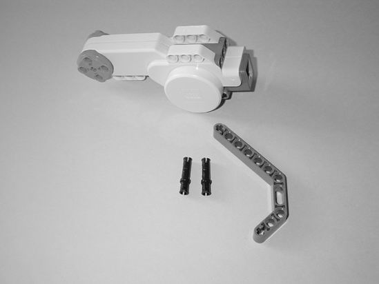
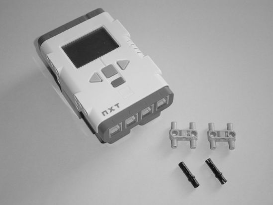
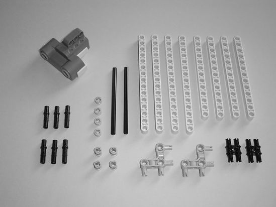
Figures 15-2 through 15-24 walk you through the steps for constructing the main body. Start with the motor and components you see in Figure 15-2.
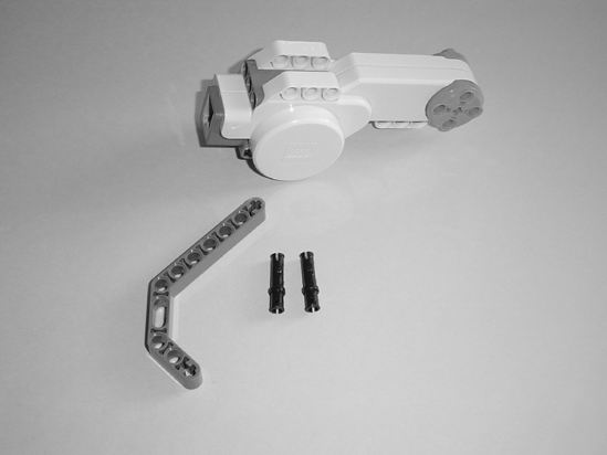
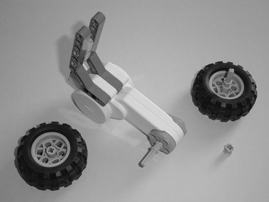
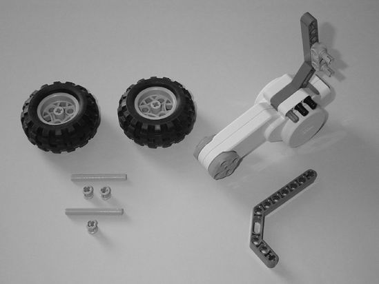
Figure 15-2. Starting components for one of the main body's wheel assemblies
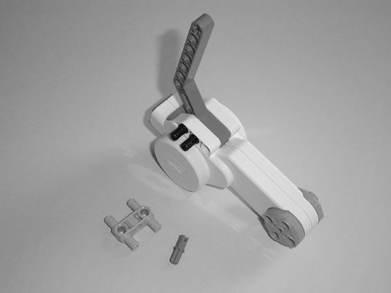
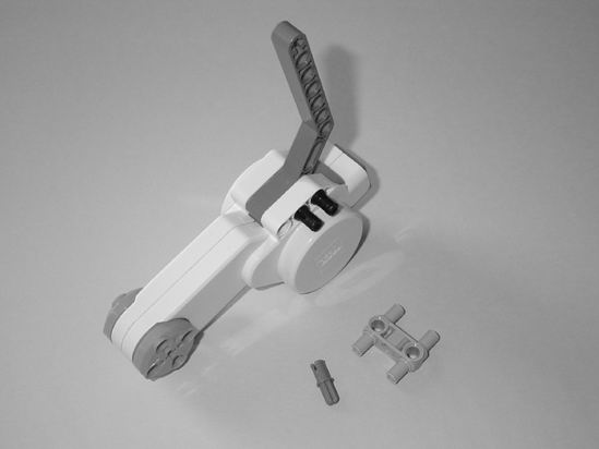
Figure 15-3. Place the long black connectors in the motor as shown to secure the angled gray component.
 |
 |
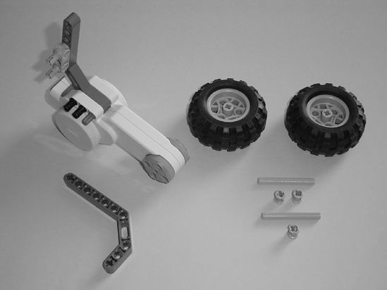
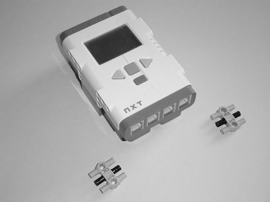
| Figure 15-4. Insert the gray pin and small blue connector as shown. | Figure 15-5. Insert the axle rod into the motor and slide the bushing on. Connect the other angled gray component as shown. |
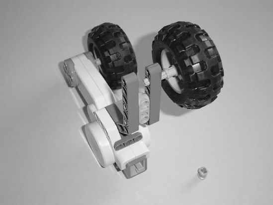
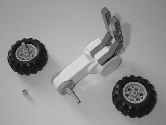
Figure 15-6. Place one tire on the axle rod. Insert the other tire into the angled gray connector as shown.
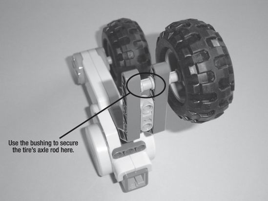
Figure 15-7. Use the bushing to secure the tire's axle rod as shown.
Now you'll perform the same steps to make the opposite wheel assembly.
 |
 |
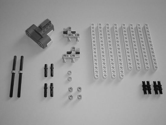
| Figure 15-8. Starting components for the main body's other wheel assembly | Figure 15-9. Place the long black connectors in the motor as shown to secure the angled gray component. |
 |
 |
| Figure 15-10. Insert the gray pin and small blue connector as shown. | Figure 15-11. Insert the axle rod into the motor and slide the bushing on. Connect the other angled gray component as shown. |
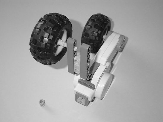
Figure 15-12. Place one tire on the axle rod. Insert the other tire into the angled gray connector as shown.
Just like Figure 15-7, use the bushing to secure the tire's axle rod in the angled gray component for Figure 15-13.

Figure 15-13. Use the bushing to secure the tire's axle rod as shown.
Now that you've completed the left and right wheel assemblies, it's time to configure the Brick (see Figures 15-14 through 15-16).
 |
 |
| Figure 15-14. The Brick and components are needed to create the main body. | Figure 15-15. Insert the long black connectors into the gray pins. |
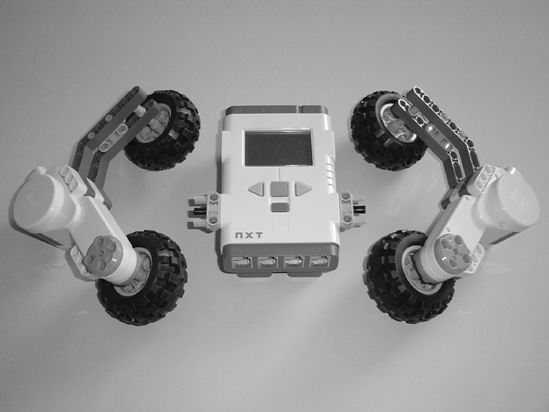
Figure 15-16. Insert the gray pins (and long black connectors) into the Brick.
Next, you'll connect the wheel assemblies to the Brick (see Figures 15-17 through 15-24).
 |
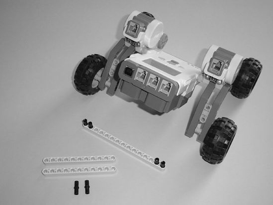 |
| Figure 15-17. Connect the right and left wheel assemblies to the Brick. | Figure 15-18. Place the four small black connectors in the 15-hole beam. |
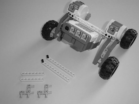
Figure 15-19. Connect the 15-hole beam to the back of the motors to secure them and place the two small black connectors in the 11-hole beams.
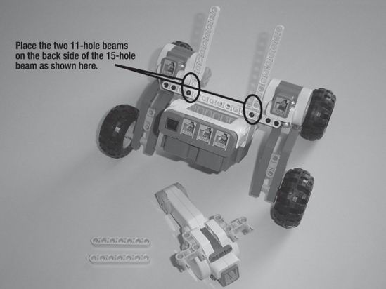
Figure 15-20. Connect the two gray pins to the motor and place the two 11-hole beams as shown.
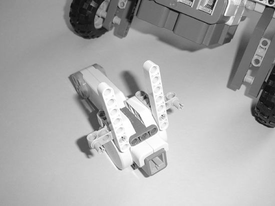
Figure 15-21. Place the two 7-hole beams on the back of the motor as shown.
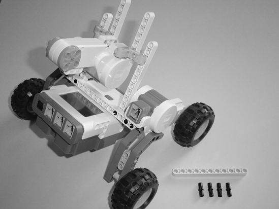
Figure 15-22. Connect the motor to the main body as shown.
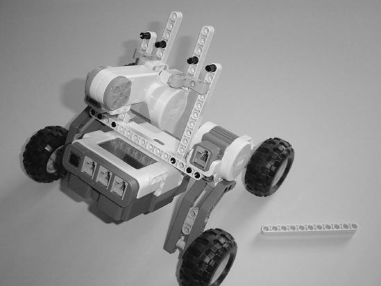
Figure 15-23. Insert the four small black connectors into the beams as shown.
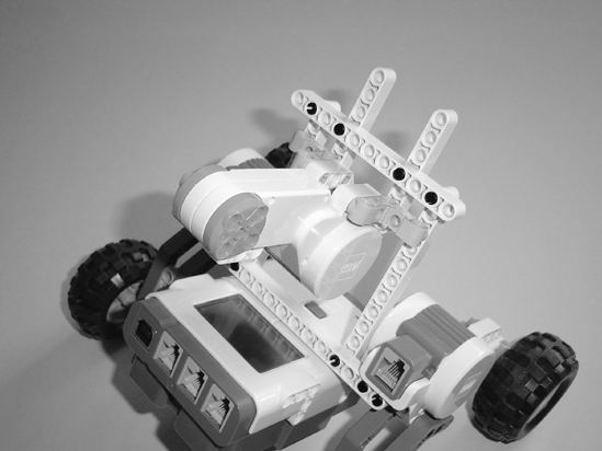
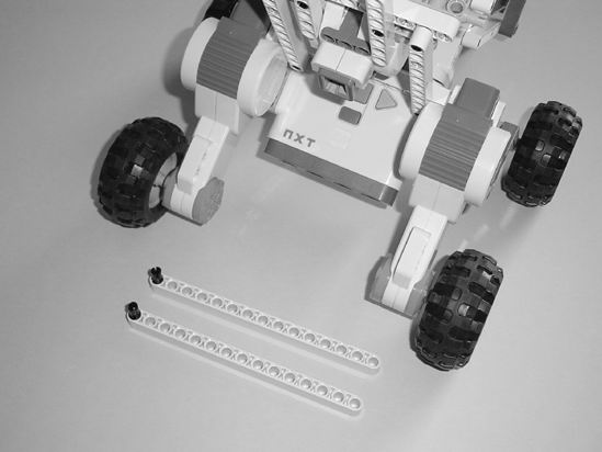
Figure 15-24. Connect the 11-hole beam to the motor mount as shown.
That's all for the main body. Up next is the lifting mechanism.
Second Section: Lifting Arm Mechanism
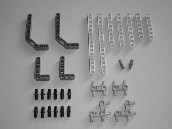
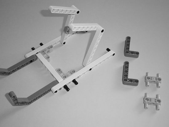
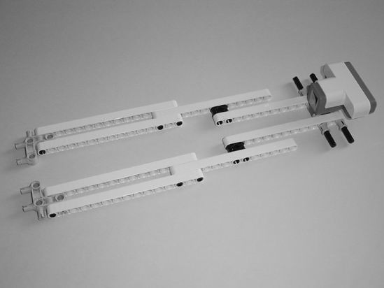
Figures 15-25 through 15-33 show you how to build the lifting arm mechanism and connect it to the main body. Start with the components shown in Figure 15-25.
 |
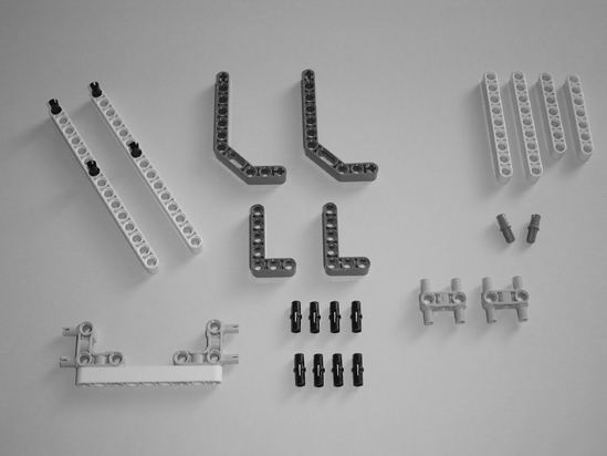 |
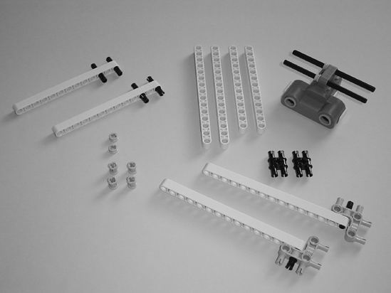
| Figure 15-25. The components used to make the lifting arm mechanism | Figure 15-26. Put the four small black connectors in the 15-hole beams and place the two gray pins in the 9-hole beam. |
 |
 |
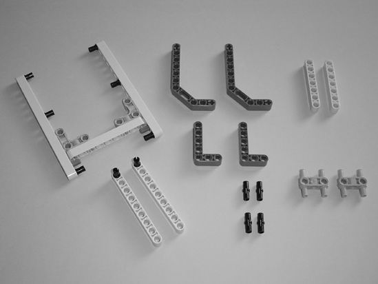
| Figure 15-27. Connect the 15-hole beams to the 9-hole beam. Insert the small black connectors as shown. | Figure 15-28. Connect the two 9-hole beams and the two angled gray beams to the main lifting mechanism as shown. |
 |
 |
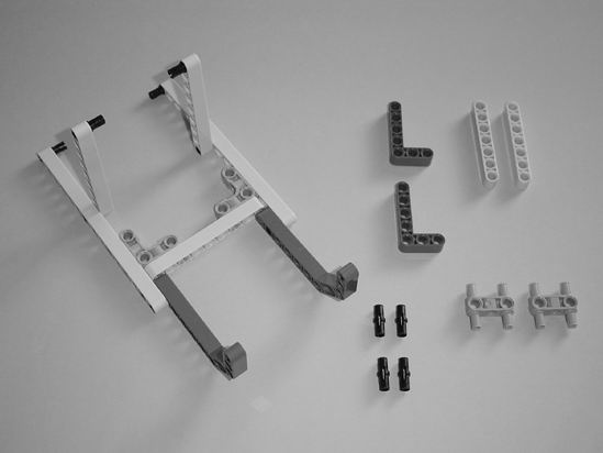
| Figure 15-29. On one side, insert two small black connectors and connect one 7-hole beam as shown. | Figure 15-30. On the other side, insert two more small black connectors and connect the remaining 7-hole beam as shown. |
 |
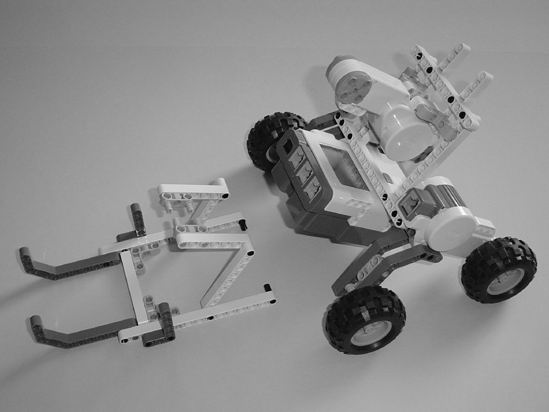 |
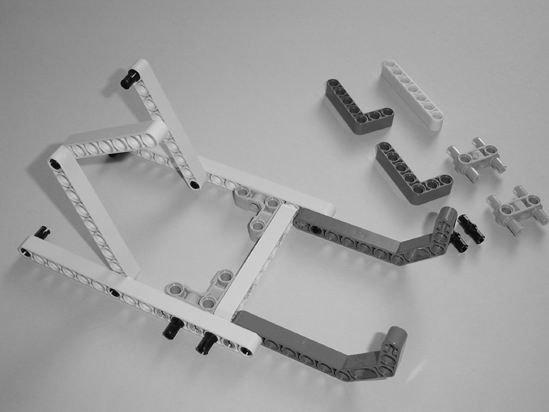
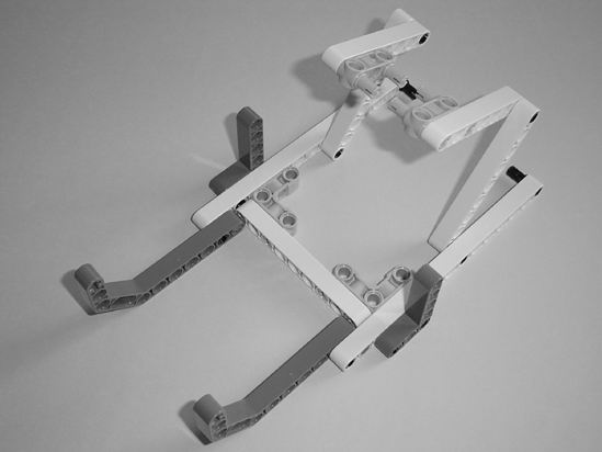
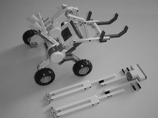
| Figure 15-31. Connect the two L-shaped beams and the two gray pins as shown. | Figure 15-32. The lifting arm connects to the main body. |
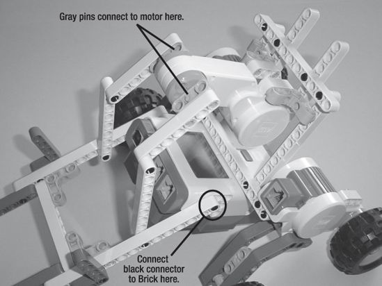
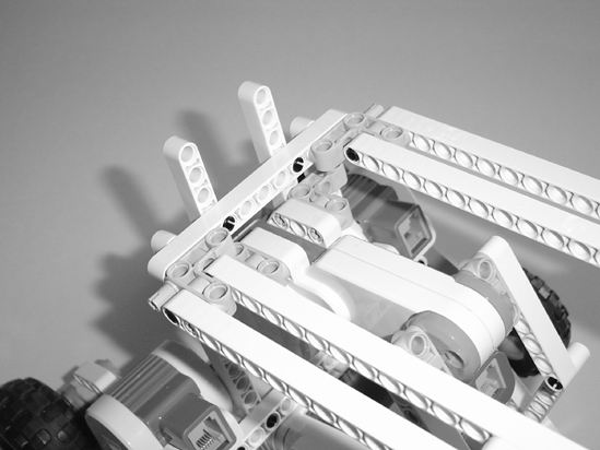
Figure 15-33. The two gray pins go in the motor as shown and the two small black connectors connect to the Brick.
Now you have the basis of the GrabberBot. All that's left is to place the Ultrasonic Sensor and the beams that the lifting arm will pin the scroll against.
Third Section: Sensors and Various Beams
You're almost done. The GrabberBot needs the Ultrasonic Sensor to detect the wall and some beams. I decided to use the Touch Sensor again as a Start button. Figures 15-34 through 15-54 show you how to complete the bot.
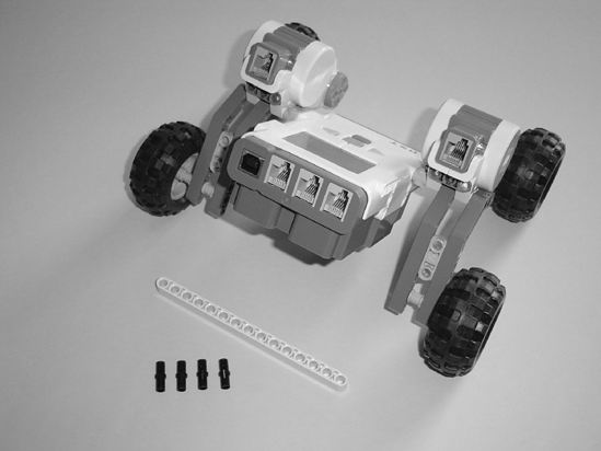
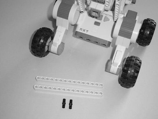
Start with the components shown in Figure 15-34.
 |
 |
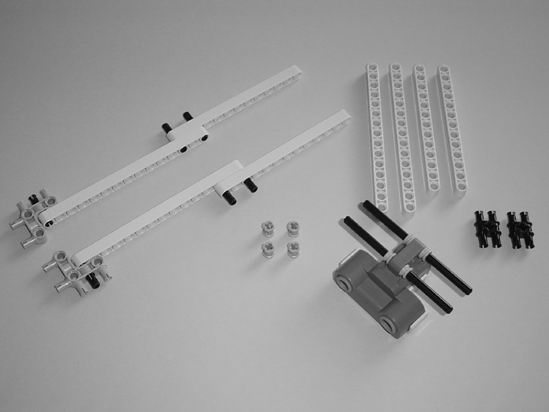
| Figure 15-34. Final components for the GrabberBot | Figure 15-35. Insert two small bushings on the axle rods and two long black connectors in the gray pins as shown. |
 |
 |
| Figure 15-36. Place four long black connectors in the 13-hole beams. Connect two gray pins to the 15-hole beams and insert the axle rods in the Ultrasonic Sensor. | Figure 15-37. Connect the 13-hole beams to the 15-hole beams. Place the other two small bushings on the axle rods as shown. |
 |
 |
| Figure 15-38. Connect the 15-hole beams and the 13-hole beams as shown. Place the black pins in the 13-hole beams and four bushings on the axle rods. | Figure 15-39. Connect everything together as shown to make the long Ultrasonic Sensor neck. |
 |
 |
| Figure 15-40. The Ultrasonic Sensor and neck will connect to the main body. | Figure 15-41. Connect the Ultrasonic Sensor and neck to the 11-hole beam on the main body as shown. |
 |
 |
| Figure 15-42. These 15-hole beams will connect to the motors for reinforcement. | Figure 15-43. Place the small black connectors in the 15-hole beams as shown. |
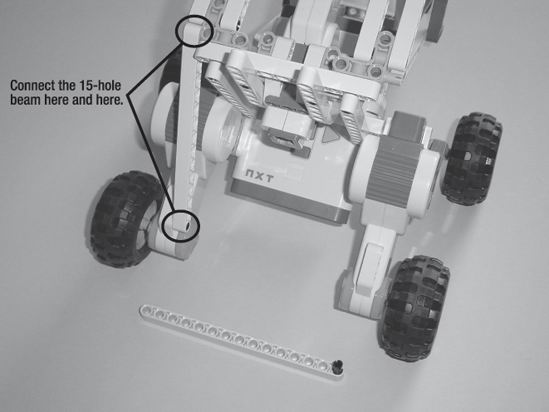
Figure 15-44. Connect a 15-hole beam to the motor and the neck assembly as shown.
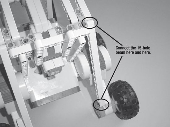
Figure 15-45. Use the other 15-hole beam and connect it to the motor and neck assembly.
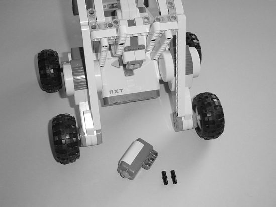
Figure 15-46. The Touch Sensor will function as a Start button.
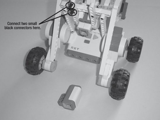
Figure 15-47. Place the two small black connectors as shown.
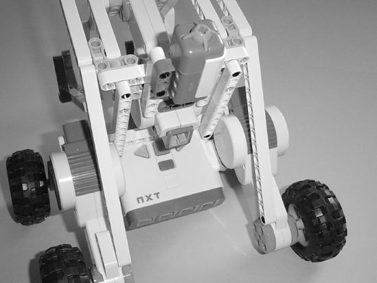
Figure 15-48. Connect the Touch Sensor.
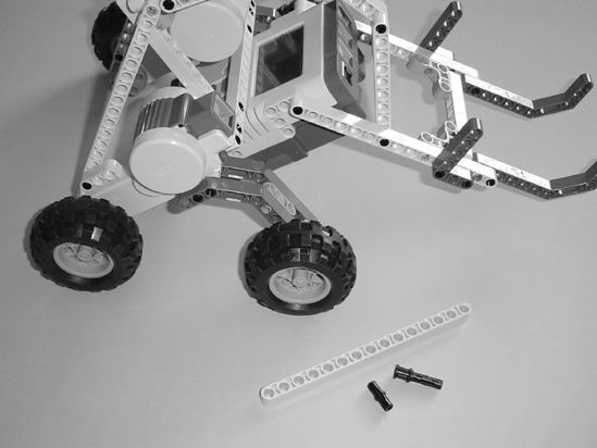
Figure 15-49. This 15-hole beam will provide strength to the GrabberBot neck.
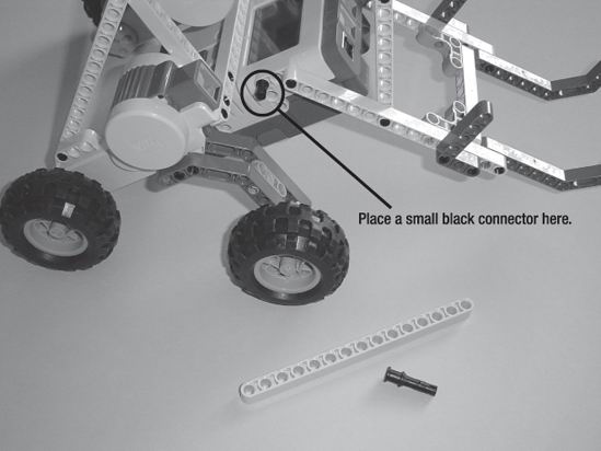
Figure 15-50. Place the small black connector as shown.
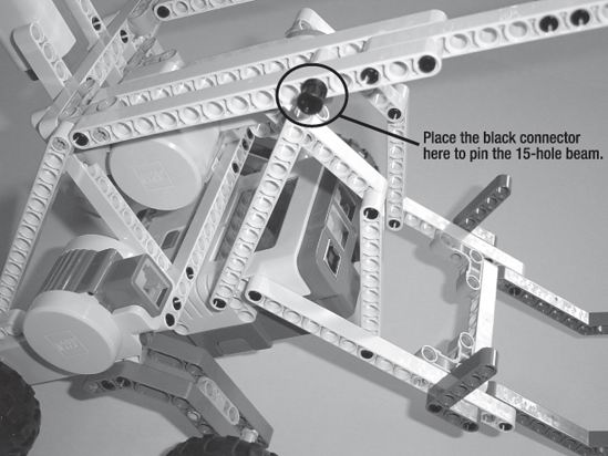
Figure 15-51. Connect the 15-hole beam and use the black connector to pin it.
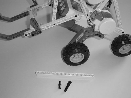
Figure 15-52. On the other side, use another 15-hole beam for reinforcement for the neck.
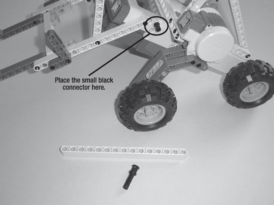
Figure 15-53. Place the small black connector as shown.
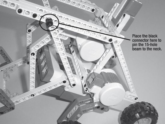
Figure 15-54. Connect the 15-hole beam and use the black connector to pin it.
Now your GrabberBot needs to be wired up and programmed. Take a look at Figure 15-55 to see how I've wired up the bot.
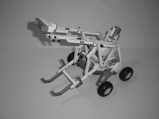
Figure 15-55. The wired-up and ready-to-be-programmed GrabberBot
Chapter 16 will show you how to program the GrabberBot so it can head down the tunnel and grab the scroll.