
CHAPTER 19
PushBot—Build It
It's time to build your final bot for the team. If you've chosen to build your own version of the PushBot, I'm confident it won't look like the one in Figure 19-1. My version of the PushBot has some unique features that I'll cover in this chapter, so if you'd like to build the version shown here, let's get started.
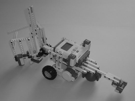
Figure 19-1. The PushBot is a fun bot to experiment on.
Note If you've built a unique version of the PushBot, please e-mail me a picture. My e-mail address can be found in the Introduction near the beginning of the book.
Step by Step
I've divided the PushBot's building instructions into three sections. The first section covers the cage mechanism. The second section will show you how to assemble the wheels and neck/Ultrasonic Sensor assembly, and the third section gives you the steps to build the main body of the PushBot.
I'll continue to add comments for figures that might be a little tricky, as well as text and arrows to point out items that might be confusing.
First Section: Motor/Cage-Arm Mechanism
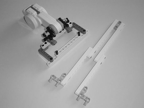
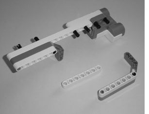
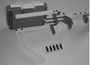
Figures 19-2 through 19-30 provide the steps for constructing the motor/cage-arm mechanism. Start with the motor and components you see in Figure 19-2.
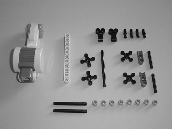
Figure 19-2. These parts are used for the cage mechanism.
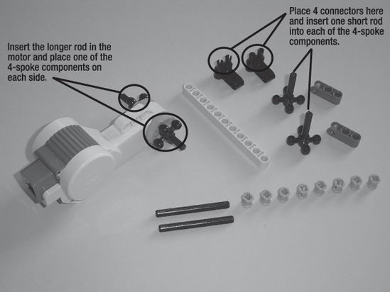
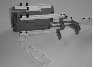
Figure 19-3. Connect the components as described.
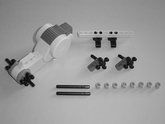
Figure 19-4. Place the 11-hole beam as shown and the two small gray components on the short rods.
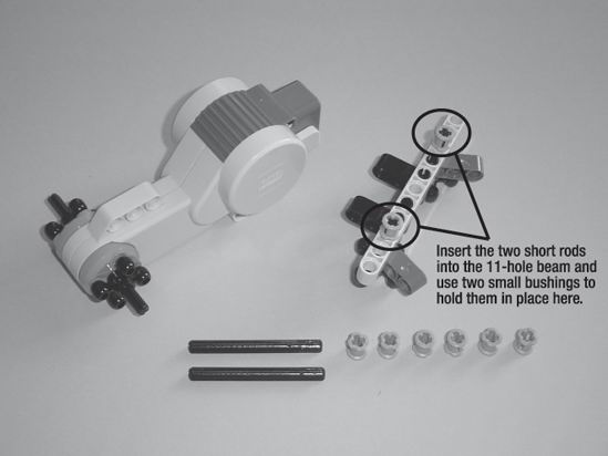
Figure 19-5. Place the components as described here.
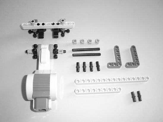
Figure 19-6. Place two small bushings on the motor's axles.
This next part can be tricky. You must insert the medium-length axles through the holes as shown in Figure 19-7 to secure the two pieces together. The two 4-spoke components on the motor are teeth that will spin the other two 4-spoke components on the cage-arm assembly. The easiest way to do this is to spin the two gray components labeled in Figure 19-7 away from the motor and then lower the cage-arm assembly.
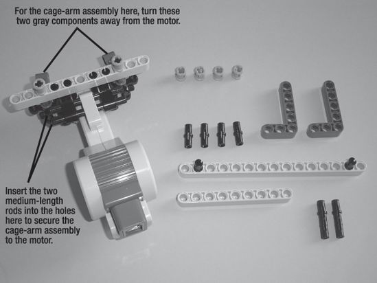
Figure 19-7. Connect the cage-arm assembly to the motor as described here.
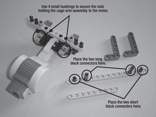
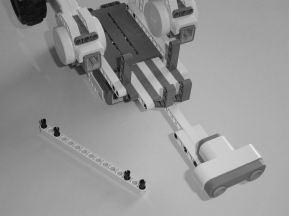
Figure 19-8. Insert the black connectors into the 15-hole beam and use four small bushings to secure the rods that hold the cage-arm assembly to the motor.
 |
 |
| Figure 19-9. Place the 9-hole beam on top of the 15-hole beam as shown. | Figure 19-10. Flip the motor/cage-arm assembly over and attach the 15-hole beam. |
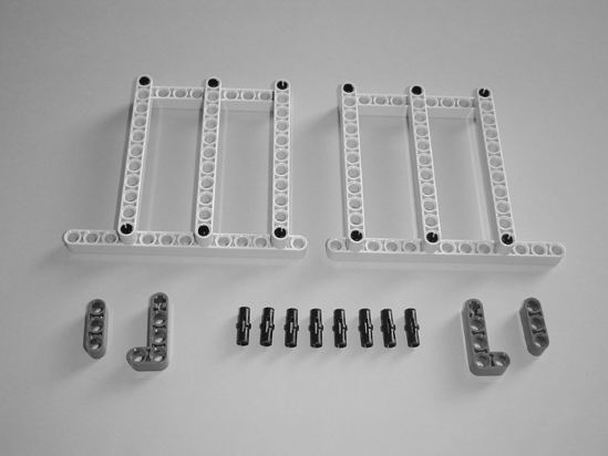
Now, set this assembly aside for a moment. Figures 19-11 through 19-18 demonstrate how to build the actual cage.
 |
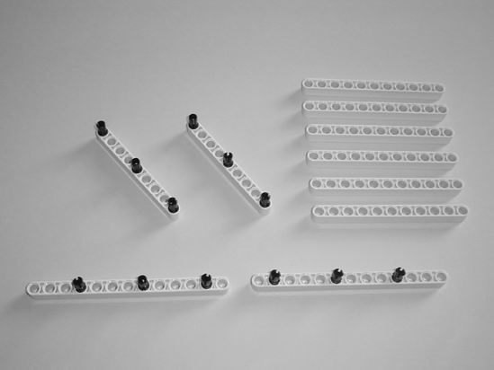 |
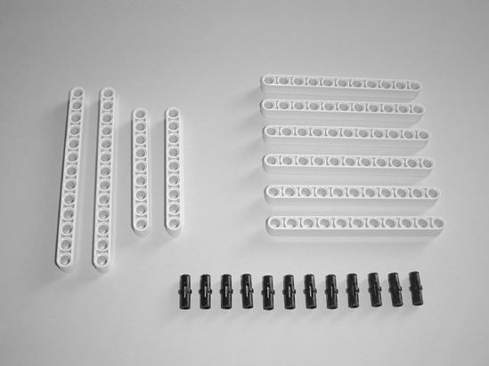
| Figure 19-11. Start with these components to build the cage's left and right side. | Figure 19-12. Place the small black connectors in the beams as shown. |
 |
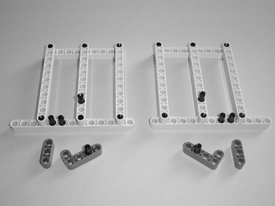 |
| Figure 19-13. Connect the six 11-hole beams as shown. | Figure 19-14. Place the small black connectors in the components as shown. |
 |
 |
| Figure 19-15. Place the small L-shaped components as shown. | Figure 19-16. Place the small 3-hole beams as shown. |
 |
 |
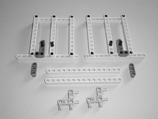
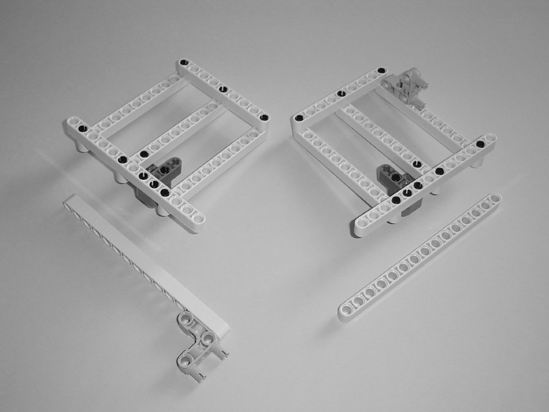
| Figure 19-17. Flip the cage assemblies over and connect the gray components as shown. | Figure 19-18. The 15-hole beams attach to the cage assemblies. |
Figures 19-19 through 19-21 demonstrate how to build the vertical support bar (to support the figurines).
 |
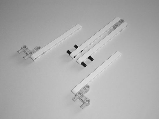 |
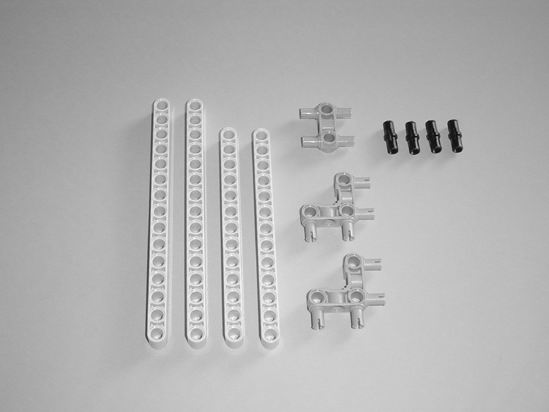
| Figure 19-19. Start with these components to build the vertical support bar. | Figure 19-20. Connect the components as shown. |
 |
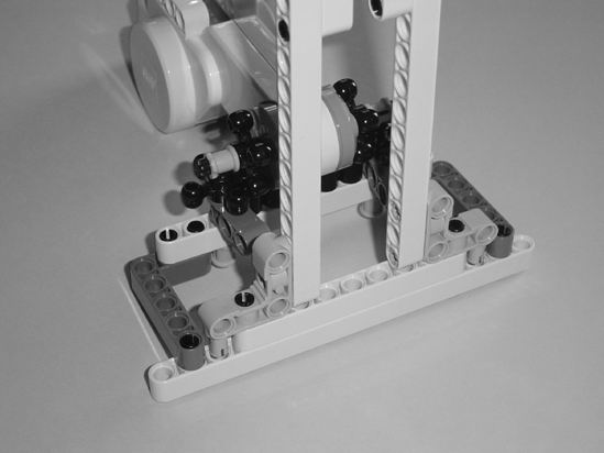 |
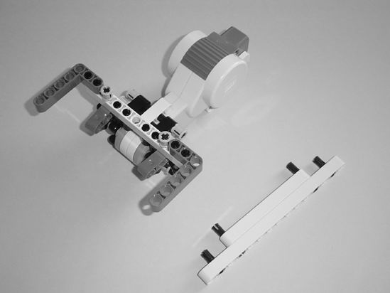
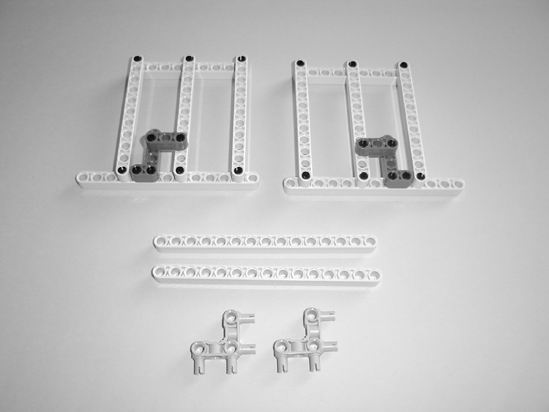
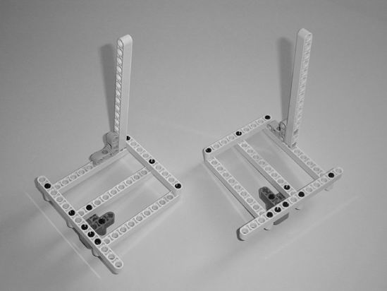
| Figure 19-21. The vertical support bar will connect to the motor/cage-arm assembly. | Figure 19-22. Insert the vertical support bar as shown. |
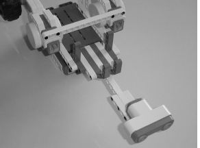
Next, you'll use four small black connectors to hold the left and right sides of the cage to the motor/cage-arm assembly (see Figure 19-23).
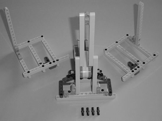
Figure 19-23. The four small black connectors will help form the cage.
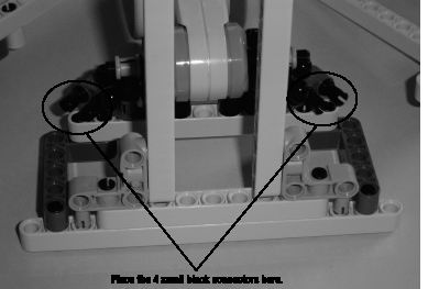
Figure 19-24. Place the four small black connectors as described.
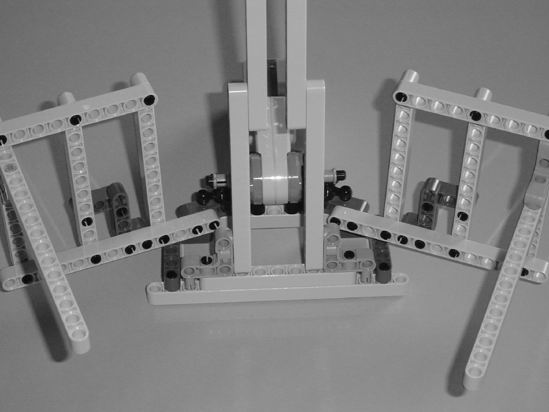
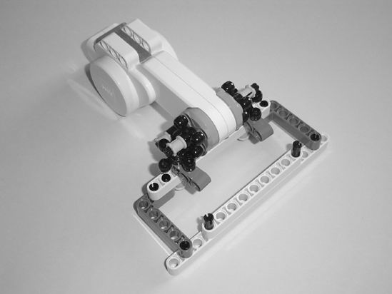
Figure 19-25. Connect the left and right sides of the cage as shown.
Some final components will be added to the motor/cage-arm assembly in Figures 19-26 through 19-30.
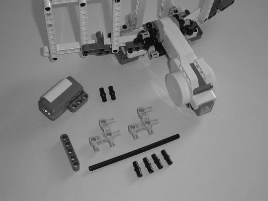
Figure 19-26. These are the final pieces for the motor/cage-arm assembly.
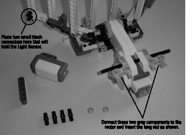
Figure 19-27. Connect the components as described.
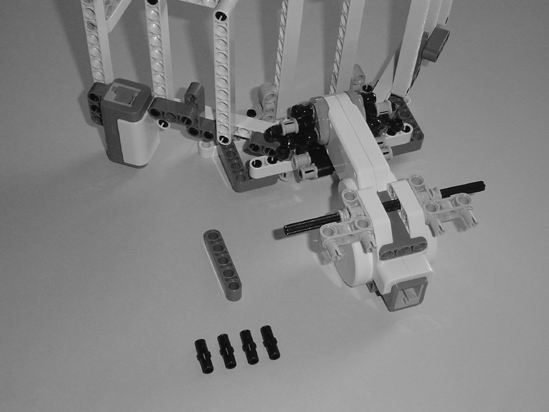
Figure 19-28. Connect the Light Sensor and use two small bushings to secure the long rod.
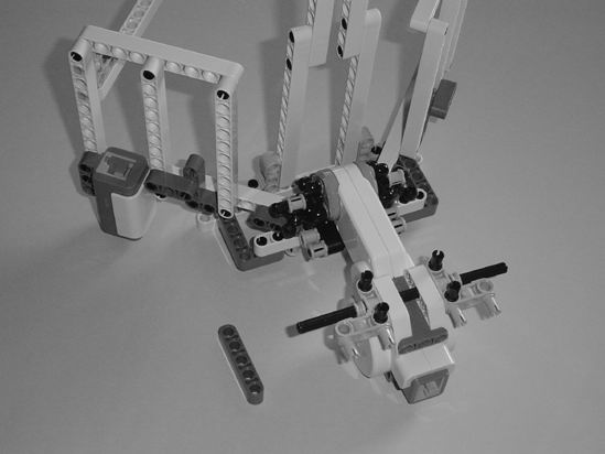
Figure 19-29. Place the four small black connectors as shown.
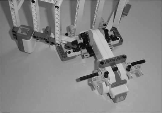
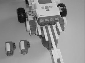
Figure 19-30. Place the 5-hole beam as shown.
Second Section: Wheels and Neck/Ultrasonic Sensor Assembly
Figures 19-31 through 19-42 demonstrate the construction of the wheels and the neck/Ultrasonic Sensor assembly.
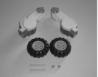 |
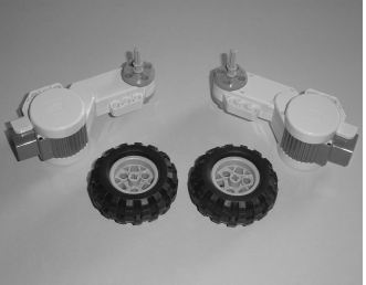 |
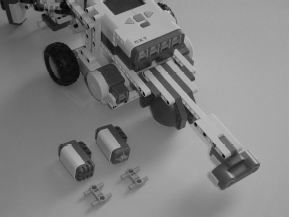
| Figure 19-31. Build the PushBot's wheels using these components. | Figure 19-32. Insert the rods into the motors and secure them with the small bushings. |
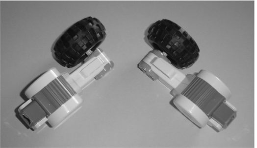
Figure 19-33 Add a tire to each motor.
Set the wheels aside for a moment and continue with the neck/Ultrasonic Sensor assembly.
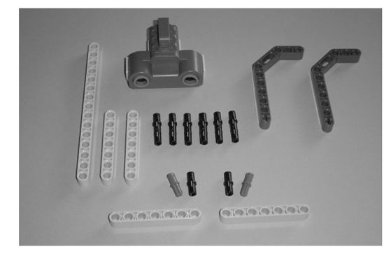
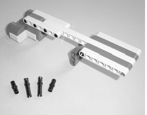
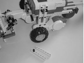
Figure 19-34. Use these components to build the neck/Ultrasonic Sensor assembly.
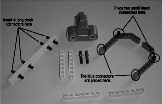
Figure 19-35. Insert the black connectors and blue connectors as shown.
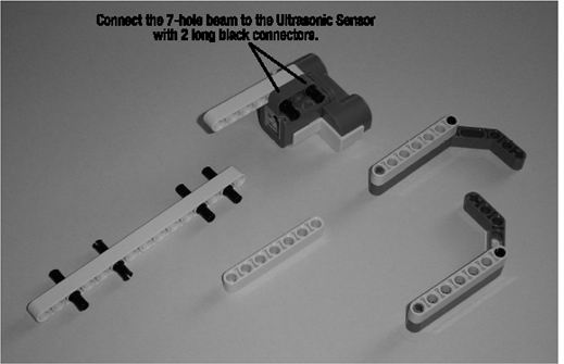
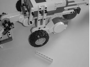
Figure 19-36. Connect the two 7-hole beams as shown and connect one 7-hole beam to the Ultrasonic Sensor using two long black connectors.
 |
 |
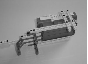
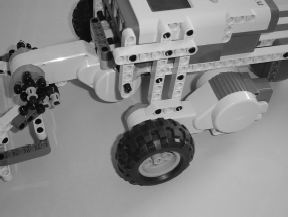
| Figure 19-37. Connect the components as shown here. | Figure 19-38. Flip the neck assembly around and connect the other components. |
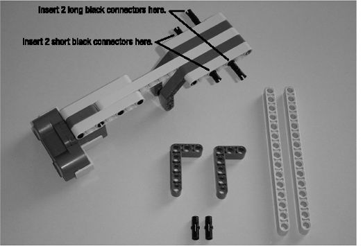
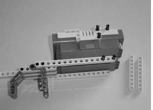
Figure 19-39. Insert the black connectors as described.
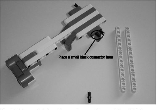
Figure 19-40. Connect the L-shaped beams as shown and place one of the small black connectors as described.
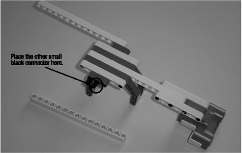
Figure 19-41. Spin the neck assembly around and place the other small black connector as described.
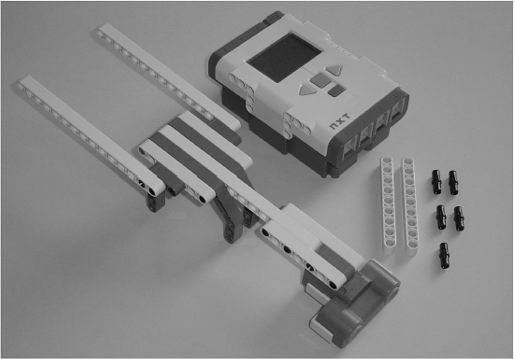
Figure 19-42. Connect the 15-hole beam to the neck assembly and gather the other components shown.
Third Section: Main Body
The PushBot is almost completed. Figures 19-43 through 19-66 demonstrate the steps needed to assemble the final bot.
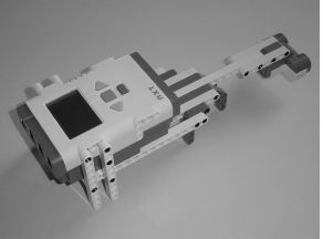
Start with the neck/Ultrasonic Sensor assembly and Brick as shown in Figure 19-43. In Figure 19-43, the Brick's "top" (where the USB port is located) is to the right.
 |
 |
| Figure 19-43. Place the five small black connectors as shown. | Figure 19-44. Connect the two 9-hole beams as shown. |
 |
 |
| Figure 19-45. Flip the Brick and neck/Ultrasonic Sensor assembly over. | Figure 19-46. Place the five small black connectors as shown. |
 |
 |
| Figure 19-47. Connect the two 9-hole beams as shown. | Figure 19-48. Flip the Brick/neck assembly over. |
 |
 |
| Figure 19-49. Insert the two small black connectors in the 9-hole beams as shown. | Figure 19-50. Connect one wheel assembly as shown and then flip the Brick/neck assembly around. |
 |
 |
| Figure 19-51. Insert the two small black connectors in the 9-hole beams as shown. | Figure 19-52. Connect the remaining wheel assembly to the Brick/neck assembly. |
 |
 |
| Figure 19-53. Place the four small black connectors in the 15-hole beam. | Figure 19-54. Connect the 15-hole beam to the two motors for reinforcement. |
 |
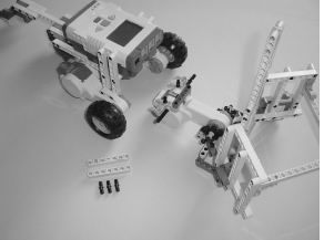 |
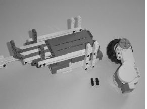
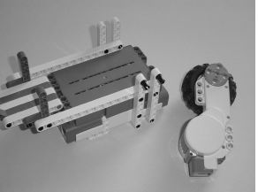
| Figure 19-55. Flip the Brick/neck assembly over and place a plastic ball as shown. | Figure 19-56. Gather the motor/cage-arm assembly and the Brick/neck assembly. |
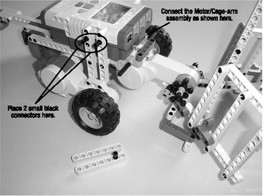
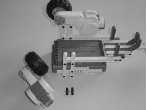
Figure 19-57. Connect the motor/cage-arm assembly to the Brick/neck assembly as shown and place the small black connectors as described.
 |
 |
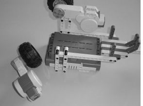
| Figure 19-58. Place the 7-hole beam (with small black connector) as shown. | Figure 19-59. Place the 7-hole beam as shown. |
 |
 |
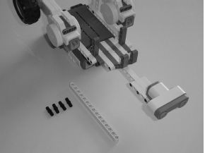
| Figure 19-62. Place the 7-hole beam (with small black connector) as shown. | Figure 19-63. Place the 7-hole beam as shown. |
 |
 |
| Figure 19-64. Gather the Sound Sensor and the Touch Sensor. | Figure 19-65. Place the two gray components as shown. |
Figure 19-66. Connect the Sound Sensor and Touch Sensor.
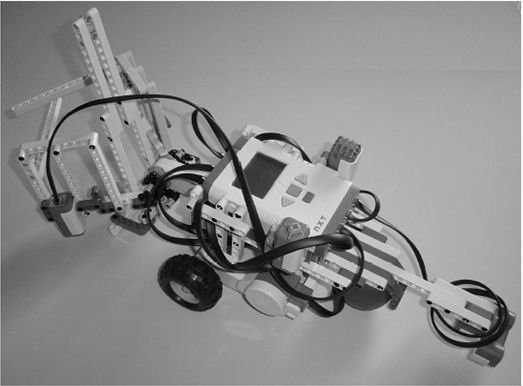
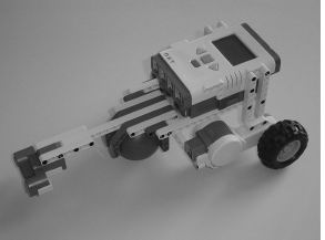
Figure 19-67. The PushBot, wired up and ready to go
In Chapter 20, I'll show you how I intend to program this PushBot to complete its tasks. Wire up this PushBot (or your own version) and continue reading. You're almost ready to send the bot into the burial chamber . . .