6
Supercontinuum and Frequency Comb Sources
6.1 Supercontinuum Sources
Broadband and spatially coherent sources in the mid‐IR, especially in the molecular fingerprint region, 3–20 μm, attract enormous interest due to the plethora of applications they are enabling, including spectroscopy, multispecies trace‐gas detection, hyperspectral imaging, and nano‐IR imaging, just to name a few. Supercontinuum (SC) generation occurs when relatively narrow‐band input pulses undergo extreme nonlinear spectral broadening to yield a broadband, spectrally continuous “white light” output. SC sources typically use a single pump laser with nano‐, pico‐, or femtosecond pulse durations and take advantage of nonlinear effects in a wide variety of media including solids, liquids, and gases, but typically in waveguiding structures. In the mid‐IR, SC sources can provide spectral coverage spanning up to several octaves and reach as far as >20 μm in wavelength. Unlike conventional broadband blackbody sources such as globars, SC laser sources are spatially coherent; they combine the brightness of lasers with extremely wide spectral coverage of blackbody radiation. Hence, SC radiation can be focused down to a diffraction‐limited spot size and, due to the dramatically increased radiance (expressed in watts per steradian per square meter), they are very beneficial for such applications as remote sensing, time‐resolved spectroscopy, the study of metamaterials, and nano‐IR spectroscopy.
Alfano and Shapiro were the first to generate an SC, which was in the visible range and extended from 0.4 to 0.7 μm [1]. They used 0.53‐μm picosecond pulses propagated through borosilicate BK‐7 glass, where short‐scale self‐focused filaments were formed with optical intensities as high as 1013 W/cm2. The authors described the effect in terms of a nondegenerate four‐wave parametric process due to the third‐order susceptibility χ(3) in the glass. The first mid‐IR SC, spanning 3–14 μm, was obtained by Corkum et al. in a 6‐cm‐long bulk GaAs crystal that was irradiated by picosecond CO2 laser pulses (λ = 9.3 μm) with the focused intensity of 1011 W/cm2 [2]. The spectral broadening mechanism originated from several nonlinear optical processes including self‐phase modulation (SPM), parametric four‐wave mixing, high‐order harmonic generation, and stimulated Raman scattering.
Since SC generation is a nonlinear effect, beam confinement in waveguides and optical fibers facilitates nonlinear processes; thus, much lower threshold peak powers, as compared to bulk materials, are required. In addition, waveguides allow modification of group velocity dispersion (GVD), a condition that is critical for efficient SC generation.
Largely speaking, the following physical processes, mostly χ(3) effects, contribute to SC generation [3–8]:
- Self‐phase and cross‐phase modulation, a result of intensity‐dependent refractive index n(I) = n0+ n2I, where n0 is the linear, and n2 is the nonlinear index of refraction, related to the third‐order nonlinear optical susceptibility.
- Parametric four‐wave mixing – the same as modulation instability if described in time domain.
- Raman scattering (which can be described as a time‐delayed resonant nonlinear response involving lattice vibrations) that results in the occurrence of redshifted spectral components.
- Soliton generation and soliton fission, feasible in the anomalous dispersion regime.
- Soliton self‐frequency shift (which can be viewed as intra‐pulse Raman scattering in the anomalous dispersion regime) leading to the amplification of the lower‐frequency part of the soliton spectrum at the expense of the higher‐frequency part.
- Dispersive wave (Cherenkov wave) emission, a process in which an optical pulse propagating in a medium with Kerr nonlinearity, anomalous dispersion, and high‐order GVD components, is scattered through a resonant‐like process to a shifted frequency; this process requires wave‐vector matching between the dispersive radiation and the excitation pulse.
- Formation of an optical intensity shock and wavebreaking, which happens in the normal dispersion regime.
The contribution of each mechanism can be very different, depending on the pulse duration, material GVD, length of the medium, and pump wavelength. With femtosecond pulses, the spectral broadening can be dominated by SPM. In the anomalous dispersion regime (that is, when the group delay increases with the wavelength), the combination of SPM and dispersion can lead to complicated soliton dynamics, including splitting of higher‐order solitons into multiple fundamental solitons (soliton fission). With picosecond or nanosecond pump pulses, the two dominant mechanisms can be Raman scattering and four‐wave mixing.
Photonic crystal fibers (PCF), tapered fibers, and waveguides are particularly attractive candidates for SC generation due to enhanced effective nonlinearity because of a very small effective modal area (a few square micrometers or less). In such structures, one can also engineer, through the design of the waveguide (WG) profile, the value and the sign of the GVD. With optical fibers, SC generation is achieved with fiber lengths that range from a few millimeters to several meters, depending on the pulse duration and the peak power [3–5].
Despite their wide application in telecommunications, the use of silica glass fibers for SC generation in the mid‐IR is limited by strong material absorption above 2.4 μm. Several non‐silica glass fibers, having much deeper mid‐IR transparency, have been used in the last decade, including tellurite, fluoride, and chalcogenide glasses, as discussed below.
6.1.1 SC from Lead‐silicate Glass Fibers
Omenetto et al. obtained a smooth SC, extending from 0.35 to 3 μm, using a highly nonlinear PCF – a special optical fiber with a built‐in microstructure − made of lead‐silicate Schott SF6 glass [9]. The reported value for lead‐silicate glass, n2 = 2.2·10−19 m2/W, is almost an order of magnitude higher than that of fused silica glass. The pump source was at λ = 1.55 μm with a pulse duration of 110 fs and a repetition rate of 80 MHz. The PCF had a 2.6‐μm core diameter (inset to Figure 6.1) and blueshifted zero‐dispersion wavelength (ZDW) at 1.3 μm, so that the pump pulses were in the anomalous dispersion region. The average power of the SC pulses detected at the output of the 5.7‐mm‐long fiber was 70 mW. The corresponding SC spectrum is shown in Figure 6.1. The authors identify two regimes of nonlinear pulse transformation in this fiber: (i) when the fiber length is much shorter than the dispersion length LD ~ τ2/β2 (here, τ is pulse duration and β2 = d2k/dω2 is the GVD), estimated to be 40 cm at λ = 1.55 μm, the soliton propagation is not important, and a symmetric SC spectrum arises from almost pure SPM, and (ii) when longer fibers are used and the SC is formed by the breakup of multiple Raman‐shifted solitons. Figure 6.2 shows the measured spectral behavior as a function of the average pump power in the fiber for the two fiber lengths: 5.7 mm and 70 cm. Figure 6.2a shows a smooth broadening of the pump pulse, typical of a SPM‐dominated process, while Figure 6.2b (longer fiber) clearly shows the spectral signature of multiple soliton fission and their subsequent redshift (indicated by the arrows).

Figure 6.1 Supercontinuum spectrum resulting from the propagation of 1.55‐μm, 110‐fs pulses in a 5.7‐mm‐long lead‐silicate PCF. The spectral region (a) was covered by an optical spectrum analyzer, region (c) by an MCT detector and a monochromator, and region (b) was not detected in the experiments. The inset shows the scanning electron microscope image of the tip of the sample.
Source: reproduced from figure 2 of [9], with permission of OSA, The Optical Society.
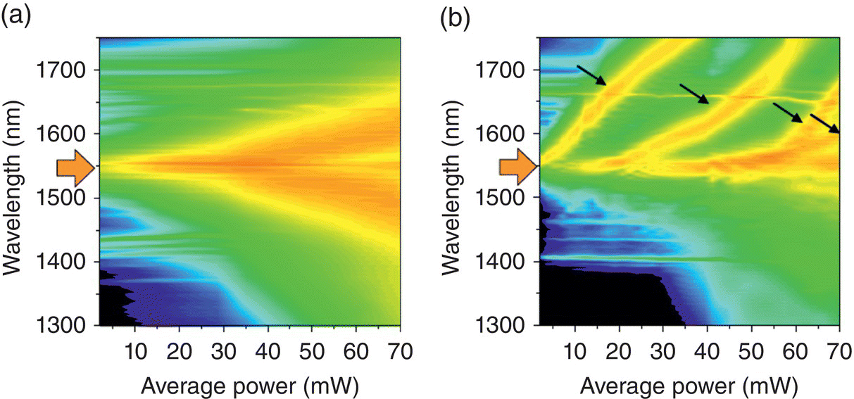
Figure 6.2 Measured spectral behavior near the pump wavelength as a function of the average pump power in the fiber for sample length of (a) 5.7 mm and (b) 70 cm.
Source: reproduced from figure 3 of [9], with permission of OSA, The Optical Society.
6.1.2 SC from Tellurite Glass Fibers
PCF can be made of tellurite glass – another material suitable for SC generation. Domachuk et al. reported an SC source extending into the mid‐IR from 0.8 to 4.9 μm [10]. The pulses with central wavelength 1.55 μm, duration 110 fs, average power 250 mW (150 mW at the input face of the fiber), and repetition rate 80 MHz were focused using a 0.5 NA aspheric lens into an 8‐mm‐long tellurite PCF. The fiber microstructure was a “wagon wheel” design shown in Figure 6.3. The microstructure is surrounded by a fiber that has a 120‐μm outside diameter. Six 120‐nm‐wide and 16‐μm long filaments support a 2.5‐μm diameter core. The effective area of the fiber mode is 1.7 μm2. The fiber design was such that the ZDW was at 1.38 μm; hence, 1.55‐μm pump pulses were in the anomalous dispersion regime. The combination of fiber microstructure and high nonlinear coefficient of the bulk tellurite glass (n2 = 2.5·10−19 m2/W) provided enhanced WG nonlinearity responsible for SC output after only 8 mm of pulse propagation. Shorter lengths are expected to result in the SC generation process that is mainly driven by SPM that typically preserves coherence of the pump and results in the smooth spectrum. Also, the use of very short fiber mitigates the relatively high loss of the tellurite glass. Figure 6.4 shows the SC spectrum, which extends from 0.79 to 4.87 μm at −25 dB level. The SC output power was measured to be 90 mW [10].

Figure 6.3 Cross‐sectional profile of the tellurite PCF in the optical microscopy (a, c) and electron microscopy (b). Scale bar in (b) is 1 μm.
Source: reproduced from figure 1 of [10], with permission of OSA, The Optical Society.

Figure 6.4 Spectrum of the SC generated by the 8 mm‐long tellurite glass PCF. The wavelength regions analyzed by the OSA and the monochromator with lead selenide (PbSe) or mercury cadmium telluride (MCT) detectors are indicated.
Source: reproduced from figure 3 of [10], with permission of OSA, The Optical Society.
6.1.3 SC from ZBLAN Fibers
The family of glasses known as ZBLAN has a composition ZrF4‐BaF2‐LaF3‐AlF3‐NaF.1 It is the most stable fluoride glass known, and is commonly used for making mid‐IR optical fibers. ZBLAN has a broad optical transmission window extending from 0.3 to 7 μm, low refractive index (n = 1.5), and small dispersion. Its attenuation can be made as low as 3 dB/km at 2.6 μm. The nonlinear refractive index of ZBLAN is n2 = 2.1·10−20 m2/W.
Hagen et al. [11] performed SC generation spanning 1.8–3.4 μm using cascaded Raman self‐shifting in two fibers connected in series: a silica fiber followed by a ZBLAN fiber. High‐power pump pulses from an erbium‐doped fiber laser (λ = 1.55 μm, 1.5 μJ, 200 kHz, 900 fs) were first coupled (Figure 6.5) into the silica fiber (Corning SMF‐28, L = 21 cm) to establish an initial redshift to the wavelengths that are greater than the ZDW of the ZBLAN fiber (1.63 μm). Next, the light was coupled into the ZBLAN fiber (KDD Fiberlabs 05C‐09, L = 91 cm) for further redshifting, with the silica and fluoride fibers coupled together either by lenses or via butt‐coupling. A 1.8–3.4‐μm continuum was generated with the spectrum shown in Figure 6.6. At an average power of the pump laser of 300 mW, 195 mW was coupled into the silica fiber, 37 mW was coupled into the fluoride fiber, and 5 mW was emitted at 1.8–3.4 μm after a germanium long‐pass filter.
Using a two‐stage (silica plus ZBLAN fiber) approach, Xia et al. produced mid‐IR SC using nanosecond pulsed excitation [12]. The pump source was a seeded multistage erbium‐doped fiber amplifier (λ = 1.553 μm) producing 2‐ns pulses at a repetition rate of 5 kHz, peak power of 4 kW, and an average power of 40 mW. The first frequency conversion stage was a 1‐to‐2‐m‐long silica single‐mode fiber (SMF). With pumping the SMF in the anomalous dispersion region, the phase‐matched modulation instability triggered the breakup of the nanosecond pulses into femtosecond pulses. In the second stage, consisting of a 2‐to‐8‐m‐long ZBLAN fiber, the primary SC was broadened by fiber nonlinearities – predominantly SPM and stimulated Raman scattering. The generated SC spanned 0.8–4.5 μm (Figure 6.7a) with an average power of 23 mW and pump‐to‐SC power conversion efficiency exceeding 50%. With an increased pump power, the same team scaled the average SC power to 1.3 W, with the spectral span of 0.8–4 μm (Figure 6.7b) [13]. Moreover, by scaling the pulse repetition rate to 3.3 MHz, the team reached an average SC power of 10.5 W [14].
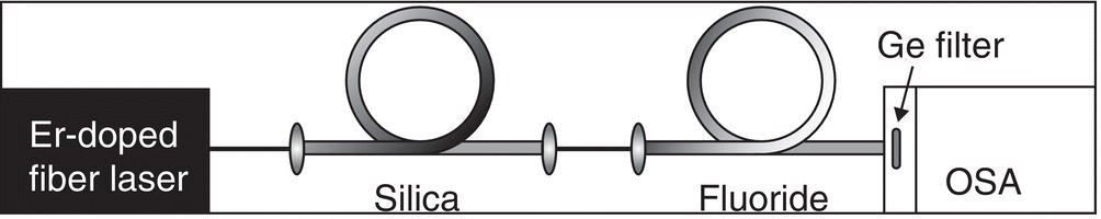
Figure 6.5 Schematic of the cascaded fiber system used to generate infrared SC. The germanium (Ge) filter is used as a long‐pass filter in an optical spectrum analyzer (OSA).
Source: reproduced from figure 1 of [11], with permission of IEEE.

Figure 6.6 Spectral emission recorded at the output of the fluoride fiber. The average output power is shown for each curve plot.
Source: reproduced from figure 2 of [11], with permission of IEEE.

Figure 6.7 (a) SC Spectrum obtained from 1 m of a silica SMF followed by 8 m of ZBLAN. The feature at 980 nm is due to the undepleted pump of the EDFA. (b) SC spectrum from 3 m of SMF followed by 13 m of ZBLAN, obtained with higher pump power.
Source: reproduced from figure 2 of [13], with permission of OSA, The Optical Society.
Using picosecond pump pulses near 2 μm, Liu et al. achieved an SC spectrum extending from 1.9 to 3.8 μm with 21.8‐W average power, from a single‐mode ZBLAN fiber [15]. The pump source was a thulium‐doped fiber master oscillator power amplifier system with the pulse width 24 ps and repetition rate 94 MHz. First, the seed laser spectrum was broadened to beyond 2.4 μm in a thulium‐doped fiber amplifier delivering 42‐W average power. This initial broadening in the amplifier was caused by the breakup of picosecond pulses into femtosecond solitons, modulation instability, stimulated Raman scattering, and SPM. Then, the output spectrum was further broadened to beyond 3.8 μm in a single‐mode ZBLAN fiber. The ZBLAN spectrum‐broadening mechanisms included a variety of nonlinear effects such as soliton self‐frequency shift, stimulated Raman scattering, and four‐wave mixing. Overall, the optical‐to‐optical conversion efficiency to the broadband SC, with respect to the 793‐nm diode laser pump for the Tm‐fiber system, was 17% [15]. Similarly, with a 2‐μm picosecond pump, Yang et al. obtained SC generation in a single‐mode ZBLAN fiber with 13‐W average power and a spectrum extending from 1.9 to 4.3 μm [16].
By reducing the fiber length to 2 cm and using high‐power femtosecond pumping (λ = 1.45 μm, pulse width 180 fs, energy per pulse 9 μJ, peak power 50 MW), SC spectrum obtained from a ZBLAN fiber was extended to 6.3 μm. The initial spectral broadening along the fiber was mainly caused by SPM; further broadening was produced by Raman scattering and four‐wave mixing [17].
6.1.4 SC from Chalcogenide Glass Fibers
Chalcogenide glasses – amorphous semiconductors based on heavy elements, such as sulfur (S), selenium (Se), and tellurium (Te), bonded to As, Ge, Sb, Ga, Si, or P – are exceptionally well suited for mid‐IR SC generation because of their (i) good long‐wavelength IR transparency due to the low (300–450 cm−1) phonon energy and (ii) high optical χ(3) nonlinearity. Typically, sulfides transmit to ~11 μm, selenides to ~15 μm, and tellurides to beyond 20 μm in the IR [18–22]. For an optical WG, the strength of the nonlinear response is characterized by the nonlinear parameter γ = n2ω0/cAeff, where n2 is a nonlinear refractive index, Aeff is the effective core area of the propagating mode, c is the speed of light, and ω0 is the central angular frequency [3].
Strong confinement of the beam in PCF, associated with the air holes surrounding the fiber core, allows a dramatic increase in the nonlinear parameter γ of the fiber device. In addition, it allows engineering of total dispersion (e.g. from normal to anomalous). By using a suspended‐core microstructured As2S3 optical fiber, El‐Amraoui et al. attained SC between 1 and 2.6 μm using a 1.56‐μm fs pump [23]. The As2S optical fiber was 68 cm long with a core diameter of 2.6 μm surrounded by three holes (Figure 6.8a). By varying the input peak power of the 1.56‐μm pump between 0.5 and 5.6 kW (average power 3.4–38 mW), the authors observed continuous broadening of the initial spectrum, which extended at the maximum pump from 1 to 2.6 μm (Figure 6.8b). For the core diameter of 2.6 μm, the estimated ZDW was at λ = 2.2 μm, which is strongly shifted, due to the influence of geometry, toward shorter wavelengths. (For comparison, bulk As2S3 glass has ZDW at λ ~ 5 μm.)

Figure 6.8 (a) Geometrical profile of a suspended core As2S optical fiber. The external fiber diameter is between 120 and 160 μm. (b) Experimental SC spectra recorded for 1557 nm fs pumping at different peak powers.
Source: reproduced from figure 9 of [23], with permission of OSA, The Optical Society.
Fiber tapering (a process of stretching an optical fiber while it is heated) provides a good alternative to PCF to dramatically increase the nonlinear parameter γ, due to a reduced cross section, and to engineer the dispersion [24, 25]. By using pulses from an erbium‐fiber mode‐locked laser (250‐fs duration, 38.6 MHz repetition frequency, and 17 mW of maximum average power), Hudson et al. produced an octave‐spanning SC in an As2S3 tapered fiber. The authors made a tapered region with a diameter of 1.3 μm and a length of 50 mm. The corresponding mode area Aeff was 0.8 μm2, the nonlinear parameter γ = 12.4 m−1 W−1 at 1.55 μm, and ZDW ~1.4 μm. As the pump power was incrementally increased, the spectrum broadened to several hundred nanometers with relatively low (<1 kW) peak powers (Figure 6.9). The mechanisms responsible for SC generation include four‐wave parametric process and high‐order soliton fission, while Raman soliton self‐frequency shift is responsible for extending the bandwidth on the long‐wavelength side [26].
Using 1‐ps pulses at 1.55 μm with 3.5‐kW peak power, Shabahang et al. [27] obtained SC from 0.85 to 2.35 μm in a composite As2Se1.5S1.5/As2S3 tapered fiber. The fiber was tapered without removing the polymer jacket that was an integral part of the fiber structure. Owing to the large index contrast, the field was strongly confined to the 480‐nm diameter chalcogenide core, while a polymer jacket provided mechanical stability.
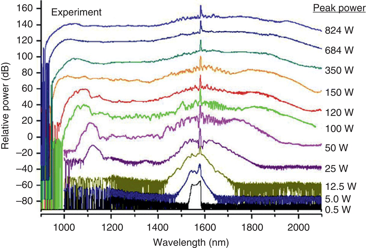
Figure 6.9 Output SC spectra from the As2S3 tapered fiber as a function of the peak pump power.
Source: reproduced from figure 4 of [26], with permission of OSA, The Optical Society.
With pump pulses at longer wavelengths one can expect deeper penetration into the mid‐IR. Sanghera et al. used λ = 2.5‐μm, 100‐fs pulses with 100‐pJ pulse energy and 1‐kW peak power to obtain mid‐IR SC spanning 2–3.4 μm using small‐core chalcogenide fibers with 1‐m length [28]. Mouawad et al. reported SC generation from 0.6 to 4.1 μm (at −40 dB level) in a 20‐mm‐long suspended core As2S3 fiber, pumped at λ = 2.5 μm with pulse duration of 200 fs and peak power of 4.9 kW [29]. The central core of the fiber was 3.4 μm in diameter and it was separated from the clad by three surrounding holes. The fiber exhibited ZDW close to 2.4 μm, i.e. the fiber was pumped in a slightly anomalous dispersion regime. The SC process was characterized by a strong SPM followed by soliton fission. Subsequent propagation in the fiber was associated with soliton dynamics and dispersive wave generation. According to the authors, the fission occurs randomly, due to the role of modulation instability. This leads to a significant degradation of SC coherence properties [29].
Marandi et al. achieved SC generation with an instantaneous span of 2.2–5 μm in a tapered As2S3 fiber [30]. Pump pulses with λ = 3.1 μm and sub‐100‐fs pulse duration were produced as a subharmonic of a 1.56‐μm erbium‐fiber pump laser in a degenerate PPLN‐based optical parametric oscillator (OPO) (Figure 6.10a). The authors used in‐situ tapering, in which case the SC spectrum was measured in real time during the tapering process, and the tapering was stopped when the spectrum reached its maximum width. The length of the tapered region was 18 mm and the diameter of the thinnest portion of the fiber was estimated to be 2.3 μm, resulting in ZDW close to 3.1 μm. The output spectrum, together with the pump spectrum, is shown in Figure 6.10b. The SC spectrum extended from 2.2 to 5 μm (at −40 dB) and was ~3 times broader (in optical frequency units) than that of the 3.1‐μm pump. The average power at the fiber output was measured to be 15 mW. According to simulations, the spectral broadening was dominated by soliton fission and suggested a high degree of SC coherence [30].

Figure 6.10 (a) Setup for SC generation in a tapered As2S3 fiber using 3.1‐μm pump from a subharmonic OPO. M2–M5, OPO mirrors; OC, OPO output coupler. (b) Spectrum of the SC output compared with a simulated spectrum. The input pump spectrum is shown at the bottom.
Source: reproduced from figure 5 of [30], with permission of OSA, The Optical Society.
A similar in‐situ tapering technique was used to demonstrate a 1‐to‐3.7 μm SC in a tapered As2S3 2.1‐mm‐long fiber that was pumped by sub‐100‐fs pulses that originated directly from a mode‐locked Tm‐doped fiber laser with 75 MHz repetition rate, center wavelength of 2.04 μm, and 23 mW average power (pulse energy 300 pJ). To shift the GVD of the As2S3 fiber to the anomalous dispersion regime, the fiber was tapered to 1.95‐μm diameter [31]. Also, with a 10‐cm‐long tapered As2Se3 fiber having a diameter of 1.6 μm, Al‐Kadry et al. produced an SC that spanned the range 1.1–4.4 μm (at −30 dB). The pump was a mode‐locked Tm‐doped fiber laser at λ = 1.94 μm with pulse duration of 800 fs [32].
Yu and coauthors achieved SC in a small‐core step‐index chalcogenide fiber with a core made of Ge‐As‐Se and the cladding made of Ge‐As‐S glass. Both glasses show broad transparency and low losses in the mid‐IR to beyond 9 μm. The fiber had an elliptical core of 4.1 × 4.6 μm and an outer diameter of 190 μm, and there were two ZDWs: at 3.2 μm and at 6 μm. By pumping an 11‐cm‐long fiber with λ = 4‐μm pulses from a femtosecond optical parametric amplifier (OPA) system at 330‐fs duration and 3‐kW peak power, the team generated an SC spanning from 1.8 to 10 μm [33]. By using a suspended core As38Se62 fiber that was 18‐cm long, had a core diameter of 4.5 μm, a ZDW of 3.5 μm, and combined with the same OPA pumping source tuned to λ = 4.4 μm, an SC spanning 1.7–7.5 μm with an average output power of 15.6 mW (peak power 5.2 kW) was obtained. The SC generation was initiated by SPM followed by soliton dynamics and soliton self‐frequency shift [34].
By keeping the fiber geometry simple and robust, but at the expense of a higher‐power pump source, Hudson et al. demonstrated broadband SC operation in a standard As2S3 step‐index fiber. The fiber had a 9‐μm diameter core and 170‐μm cladding, and the pump source was an optical parametric chirped pulse amplifier (OPCPA) system operating at 3.1 μm with pulse energy of up to 18 μJ and pulse duration of 67 fs. The SC spectral bandwidth of 1.6–5.9 μm (at −20 dB level) was achieved at the peak pump power of 520 kW [35]. The SC average power was 8 mW. The pump wavelength of 3.1 μm was in the normal dispersion range of the fiber, and the spectral broadening was mainly driven by SPM, with Raman shifting extending the long wavelength edge.
Robichaud et al. reported a cascaded mid‐IR SC source spanning 3–8 μm and based on a low‐loss commercial As2Se3 step‐index fiber (ZDW 8.9 μm) that was pumped by another SC source with a span of 3–4.2 μm. The latter was based on a seeded (λ = 2.8 μm) erbium‐doped ZrF4 fiber pumped at 980 nm, which served simultaneously as an amplifier and SC generator [36]. A maximum average output power of 1.5 mW was obtained at 3–8 μm at a repetition rate of 2 kHz. The SC output was single mode for the wavelengths >5 μm. Since the As2Se3 fiber exhibited normal dispersion up to ∼8.9 μm, the spectrum broadening was mainly due to SPM.
By launching intense (>3 MW peak power) 100‐fs pulses at 1 kHz repetition rate with a central wavelength of either 4.5 or 6.3 μm into an 85‐mm‐long high numerical‐aperture step‐index chalcogenide glass optical fiber, Petersen et al. generated mid‐IR SC extending beyond 13 μm [37]. The fiber had a 16‐μm‐diameter As40Se60 core surrounded by a Ge10As23.4Se66.6 cladding. Because of the large core, the fiber was effectively multimode with the calculated ZDW of 5.83 μm. When pumping in the normal dispersion regime at 4.5 μm with the peak power up to 3.3 MW (average power 350 μW, 350 nJ/pulse), the pulses initially undergo strong SPM, possibly leading to wave‐breaking, owing to self‐steepening and third‐order dispersion, which causes a significant part of the light to be blueshifted. The redshifting part eventually crosses the ZDW, at which point soliton dynamics, in particular Raman‐induced soliton self‐frequency shifting, dominates further spectral broadening (Figure 6.11a and b). When pumping in the anomalous dispersion regime at 6.3 μm, just above the ZDW of 5.83 μm, with the peak power up to 7.15 MW (average power 760 μW, 760 nJ/pulse), the pump pulse transforms into a higher‐order soliton that rapidly breaks up into multiple fundamental solitons through soliton fission and radiates dispersive waves at a wavelength that is phase‐matched to the solitons in the normal dispersion regime (Figure 6.11c and d).
By combining a recently developed ultrafast fiber laser based on holmium 5I6 − 5I7 transition at λ = 2.9 μm (pulse duration 230 fs, peak power 4.2 kW, repetition rate 42 MHz) with a polymer‐protected all‐chalcogenide (As2Se3 core and As2S3 cladding) tapered fiber, where the original As2Se3 core diameter of 14 μm was reduced in the tapered “microwire” section to 3 μm, Hudson et al. demonstrated an SC spanning 1.8–9.5 μm (at −20 dB) with an average power of >30 mW [38]. The microwire diameter has been optimized to minimize chromatic dispersion at 2.87 μm (β2 = 0.29 ps2/m), leading to normal dispersion at and around the pump laser wavelength. The SC in this all‐normal dispersion regime was driven, according to the authors, by two sets of processes: coherent SPM and optical wave‐breaking, and incoherent stimulated Raman scattering and four‐wave mixing. Figure 6.12 shows the layout of the SC source, as well as the spectrum as a function of the peak power.
Cheng et al. designed a step‐index fiber with near‐zero flattened dispersion based on As2Se3 (core) and AsSe2 (cladding) glasses fabricated by the rod‐in‐tube drawing technique. The pump source was based on difference frequency generation (DFG) and was tunable from 2.4 to 11 μm (pulse duration 170 fs, repetition rate 1 kHz). At the pump wavelength of 9.8 μm and 3‐mW average power, the authors demonstrated SC spectrum spanning 2–15.1 μm in a 3 cm‐long fiber. The spectrum broadening took place in the region of anomalous dispersion and was dominated, according to the authors, by the fission of the higher‐order solitons [39]. By using a low‐loss double‐cladding telluride glass fiber pumped by the output of an OPA at λ = 7 μm (pulse width 150 fs, repetition rate 1 kHz) and by operating in the normal dispersion regime, Zhao et al. produced a 2–16 μm mid‐infrared SC. The fiber was fabricated using an extrusion method and had a (Ge10Te43)90‐AgI10 core with a diameter of 20 μm and two claddings: the first was (Ge10Te40)90‐AgI10 and the second Ge10Sb10Se80 [40].
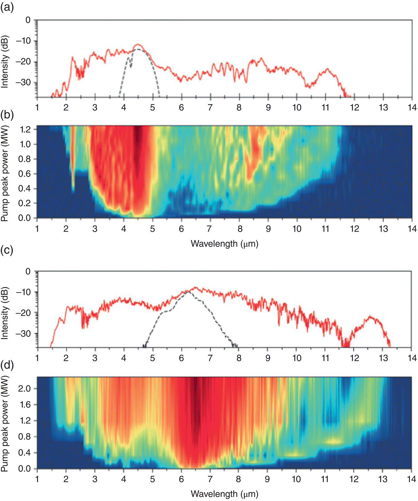
Figure 6.11 Experimental SC results with 4.5 and 6.3 μm pump [37]. (a) Input pump spectrum at 4.5 μm (dashed line) and spectral profile at maximum pump power (solid line). (b) Spectral evolution with increasing pump peak power at 4.5 μm, showing a gradual redshift of distinct soliton peaks above the ZDW and a combination of SPM and dispersive waves below the pump wavelength. (c) Input pump spectrum at 6.3 μm (dashed line) and spectral profile at maximum pump power (solid line), showing a broad, flat supercontinuum (1.64–11.38 μm at −20 dB) followed by a strong spectral peak extending the spectrum all the way to 13.3 μm. (d) Spectral evolution with increasing pump power, showing the gradual redshift of a distinct spectral peak at the long‐wavelength edge and the corresponding formation and blueshift of dispersive waves.
Source: reproduced from figures 4 and 5 of [37], with permission of Springer Nature.
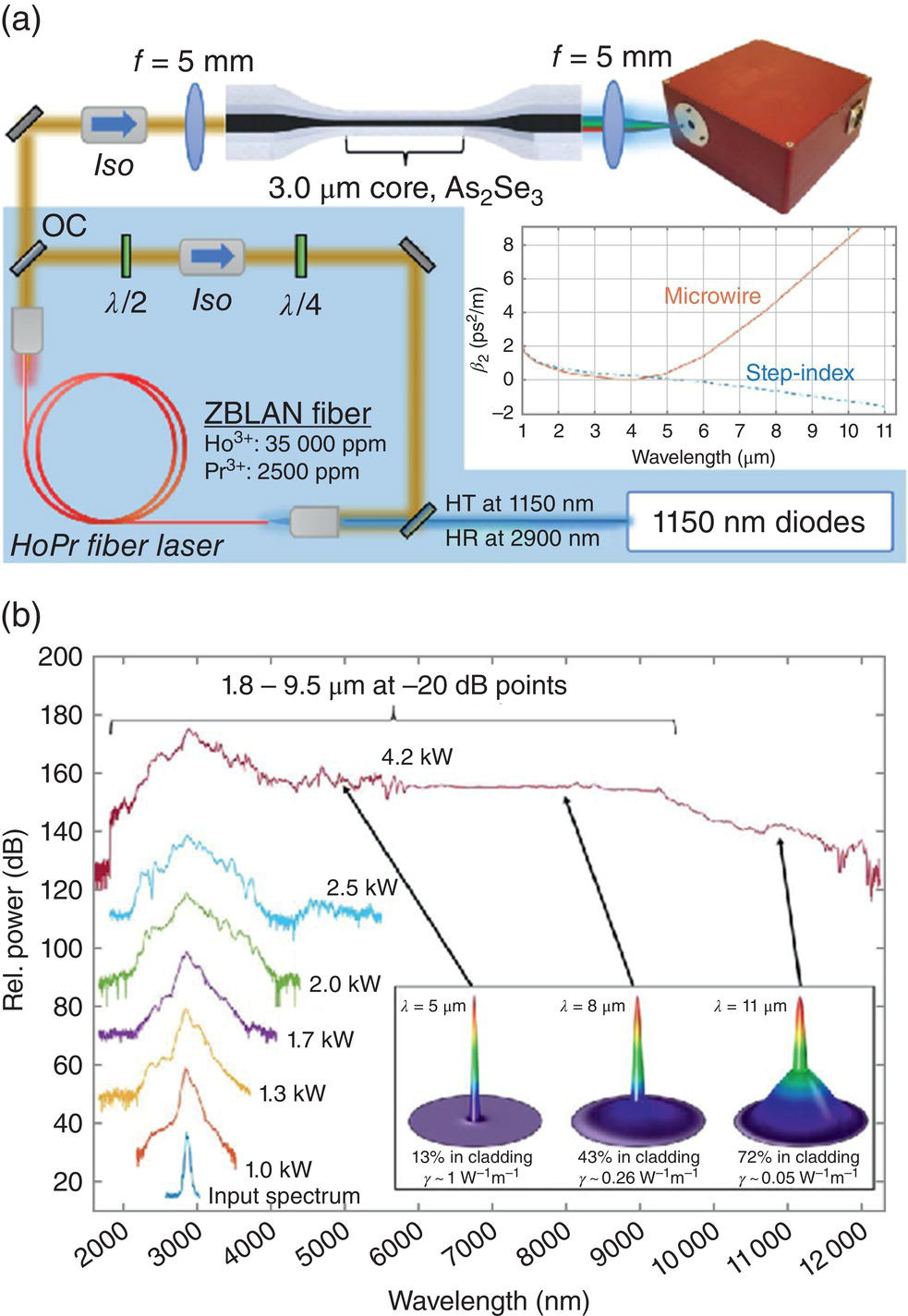
Figure 6.12 (a) Layout of the 1.8–9.5‐μm supercontinuum generator [38]. The 2.9‐µm holmium laser output passes through an isolator (>40 dB suppression) and is focused into the core of the tapered fiber. The output is collected using a ZnSe lens and focused into a spectrometer. The inset shows the calculated dispersion of both the untapered step‐index fiber and the microwire (tapered) section. (b) Spectral broadening as a function of the peak power (vertically offset for clarity). The inset shows the mode profile in the tapered section (3 μm core diameter), as well as the nonlinear parameter γ at various wavelengths.
Source: reproduced from figures 1 and 4 of [38], with permission of OSA, The Optical Society.
6.1.5 SC from Waveguides
Thanks to their small core size (typically <1 μm), nonlinear waveguides enable high peak power densities at modest average powers and hence show great promise for the realization of compact SC generators. Highly nonlinear materials such as chalcogenide glasses or silicon are extremely suitable for SC generation. Similar to fibers, dispersion engineering is an essential condition to achieve efficient SC generation.
Lamont et al. reported a mid‐IR SC produced in a dispersion‐engineered highly nonlinear As2S3 planar WG pumped at 1.55 μm [41]. The WG was 60 mm long with a cross section of 2 by 0.87 μm resulting in a nonlinear parameter γ = 10 m−1 W−1 (γ = ωn2/cAeff, where n2 is a nonlinear refractive index, Aeff is the area of the propagating mode, c is the speed of light, and ω is the angular frequency) and anomalous dispersion between 1.51 and 2.17 μm (TM mode). Laser pulses at λ = 1.55 μm with the peak power 68 W, pulse energy 60 pJ, and the average power 0.6 mW were launched into the WG, resulting in SC spectra with a span of 1.1–2.5 μm (−60 dB level, Figure 6.13). The primary nonlinear process driving the SC generation was four‐wave mixing with some contribution of Raman shift and soliton fission.
Xie et al. [42] generated SC spanning 1.2–3.6 μm by using an As2S3‐silica “double‐nanospike” WG pumped by mode‐locked Cr:ZnS laser pulses at λ = 2.35 μm (average power 360 mW, pulse repetition rate 90 MHz, pulse energy 4 nJ, pulse duration 100 fs). The waveguides used in the experiment had a hybrid As2S3‐silica structure: a 3.2‐μm‐diameter chalcogenide wire was created inside a silica capillary fiber. In order to improve the coupling efficiency into such high numerical aperture waveguides, inverse nanotapers were created at both ends of the WG (hence “double‐nanospike”). The combination of the optimized GVD and high nonlinearity provided by the As2S3‐silica hybrid WG enabled a 100‐pJ‐level pump pulse energy threshold for octave‐spanning spectral broadening. Numerical simulations, according to the authors, show that the generated SC is highly coherent over the entire wavelength span, which is important for the future realization of broadband frequency combs. For direct comparison, the authors measured an SC generated from a commercially available single‐mode As2S3 fiber (IRFlex IRF‐S‐5, effective mode area 28 μm2) pumped by the same Cr:ZnS laser. Even with six times higher pulse energy (1.23 nJ), the SC bandwidth was only 1.7–3 μm, half as wide in frequency units as compared to the case of the nanospike WG [42].
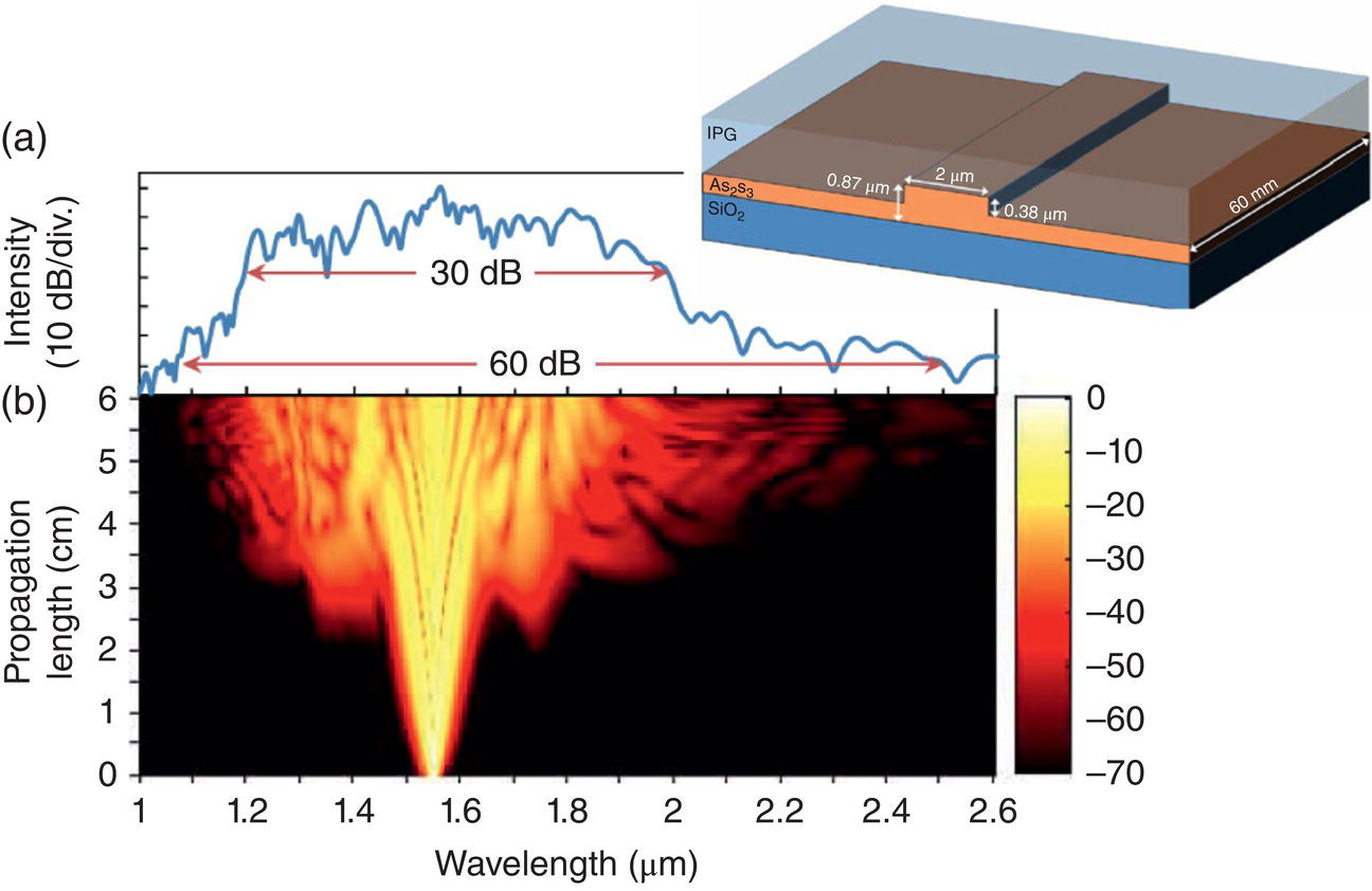
Figure 6.13 (a) Measured SC spectrum for an input pulse with 68 W peak power [41]. (b) Simulated spectral evolution along the waveguide for the same input pulse. Inset shows the waveguide structure (IPG, inorganic polymer glass).
Source: reproduced from figure 6 of [41], with permission of OSA, The Optical Society.
A broadband SC spanning from 1.8 to >7.5 μm was produced by pumping a rib WG made of GeAsSe chalcogenide glass, with 320‐fs pulses from an OPA at λ = 4 μm (Figure 6.14) [43]. The WG was 2.5 × 4 μm in cross section, 1‐cm long, and was designed to have anomalous dispersion for the wavelengths between 3.06 and 5.8 μm, such that the 4‐μm pump was approximately in the middle of this range. Given short pulse duration and short length of the WG, the SC process was dominated, according to the authors, by the soliton fission process. The total output SC power was 20 mW at the input power of 160 mW (3.3 kW peak inside the WG).
Silicon has attracted great interest as a platform for both linear and nonlinear integrated photonics for at least two decades. While its primary applications have been in the telecom window near 1.5 μm, the capability of exploiting its full transparency window to 8 μm in the mid‐IR is highly attractive. Silicon offers high third‐order nonlinearity that is similar to that of As2S3 chalcogenide glass and an additional important advantage of compatibility with complementary metal‐oxide–semiconductor (CMOS) technology. Lau et al. reported SC generation on a silicon chip, with the spectrum extending to >3.6 μm [44]. The silicon‐on‐insulator (SOI) WG had a cross section of 320 × 1210 nm, a length of 2 cm, and was engineered to exhibit zero GVD wavelength on each side of the 2.5‐μm pump. Figure 6.15a shows the GVD of the WG for the fundamental transverse electric (TE) mode. The WG was pumped with 300‐fs pulses at a repetition rate of 80 MHz and an average power of 3 mW (125 W peak). According to the authors, the SC was characterized by soliton fission and dispersive radiation across the two zero GVD wavelengths. As seen from Figure 6.15b, the spectral span at λ = 2.5‐μm pump was from 1.5 to 3.67 μm (although with some gaps in the spectrum).
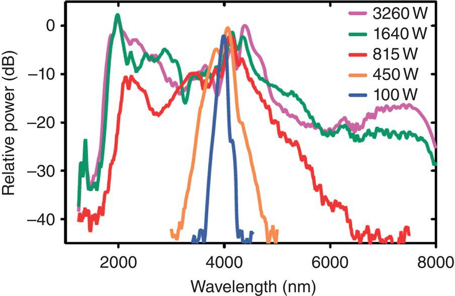
Figure 6.14 Output SC spectra obtained from a GeAsSe chalcogenide glass waveguide pumped with 320‐fs pulses at λ = 4 μm at different peak powers.
Source: reproduced from figure 3 of [43], with permission of Wiley.
By utilizing dispersion‐engineered silicon‐on‐sapphire (SOS) nanowires, Singh et al. demonstrated an octave‐spanning SC [45]. The SOS WG used in experiments had a cross section of 2400 nm by 480 nm, and was engineered to exhibit zero GVD wavelengths at 3.3 and 7.1 μm. The WG was pumped into the TE mode of the nanowire with 320‐fs pulses at λ = 3.7 μm from an OPA at a repetition rate of 20 MHz and an average power of 12 mW. The widest continuous spectrum achieved at the −30 dB signal level was from 1.9 to 5.5 μm. According to the authors, the SC bandwidth was mainly limited by the four‐photon absorption (4PA), causing high loss as well as narrowing of the spectrum (the maximum pump intensity reached 100 GW/cm2 in this experiment). Overall, these results establish SOS as a promising new platform for integrated nonlinear photonics in the mid‐IR.
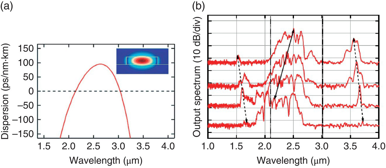
Figure 6.15 (a) Group‐velocity dispersion curve for the fundamental TE mode of an SOI waveguide. The waveguide cross section and the mode profile are shown in the inset. (b) Experimentally measured output spectra as the pump was tuned from 2.165 to 2.5 μm. Dashed lines show the resulting shift of dispersive waves generated near 1.5 and 3.6 μm. Zero‐GVD wavelengths (2.1 and 3.0 μm) are indicated by vertical lines.
Source: reproduced from figure 2 of [44], with permission of OSA, The Optical Society.
Typically, SC generation has been performed in waveguides using third‐order, χ(3), nonlinearities. Phillips et al. demonstrated SC generation in a WG based on periodically poled lithium niobate (PPLN), a material with high χ(2) nonlinearity [46]. The pump was a Tm‐doped fiber oscillator–amplifier system at λ = 1.94 μm, with 97‐fs pulse duration, 72 MHz repetition rate, and 9‐nJ pulse energy (average power 650 mW). The pulses propagated through an 18.5‐mm‐long PPLN WG with a quasi‐phase‐matched period of 22.1 μm. The measured SC spectrum spanned from 1.35 to 2.8 μm at −40 dB level. According to the authors, the spectral broadening occurred from cascaded phase shifts associated with phase‐mismatched second harmonic generation of the pump (a cascaded χ(2) nonlinearity leading in effect to a χ(3) nonlinearity). In addition, SC was enhanced by stimulated Raman scattering and SPM from the intrinsic χ(3) nonlinearity. Furthermore, the authors have shown that the SC source preserves temporal coherence of the pump and can be used for self‐referencing of the Tm fiber oscillator via f–2f and 2f–3f interferometry [46].
6.1.6 SC from Bulk Crystals
Broadband mid‐IR supercontinua can be obtained by pumping bulk materials, although at the expense of high peak powers and low repetition rates. Silva et al. produced a 0.45–4.5‐μm SC via filamentation in a 2‐mm‐thick YAG plate. The YAG sample was pumped with 85‐fs pulses at 3.1‐μm wavelength, repetition rate 160 kHz, pulse energy 6.9 μJ, and a beam spot size of 50 μm [47]. (See Table 6.1 for more details.) Yu et al. achieved SC spanning 2.5–7.5 μm by pumping a 5‐mm‐long GeAsS sample with 20‐MW‐peak‐power 150‐fs pulses at λ = 5.3 μm in the anomalous dispersion regime [49]. Four‐wave mixing and SPM were, according to the authors, the dominant mechanisms for SC generation. Also, the authors indicated that the self‐focusing effect could have contributed to SC generation [49]. Liao et al. achieved SC covering 0.2–8.0 μm in an 18‐mm‐thick piece of ZBLAN fluoride glass through beam filamentation. The researchers used 1.13‐MW‐peak‐power 180‐fs pulses at 1.6 μm (normal dispersion regime), with a repetition rate of 1 kHz. The pump‐to‐SC conversion efficiency was 67% [50].
Multi‐octave mid‐IR SC generation has been investigated in bulk ZnS and ZnSe, in the regime where the high peak power (~100 MW) of the incoming femtosecond pulses exceeded the critical power of self‐focusing (~0.5 MW), thus leading to beam filamentation playing a significant role in the enhancement of the spectral broadening [51–54]. Liang et al. achieved a 0.5–4.5 μm SC span (this span includes second and third harmonics of the pump) in ZnS with the focused λ = 2.1‐μm pulses from an OPCPA, having 5‐μJ pulse energy, 27‐fs duration, and 1‐kHz repetition rate [51]. Suminas et al. produced an SC spanning 0.6–4.2 μm in ZnSe using pulses at λ = 2.4 μm (3‐μJ pulse energy, 100‐fs pulse duration, 1‐kHz repetition rate) [52]. Mouawad et al. used high‐peak‐power (10‐μJ pulse energy, 1‐kHz repetition rate) fs pulses at a longer wavelength (λ = 5 μm), that is near ZDW (≈4.8 μm) of ZnSe to produce an extremely broad SC spanning 0.5–11 μm in an 8‐mm‐long bulk ZnSe crystal (Figure 6.16). According to the authors, the underlying physical mechanisms of SC generation were multi‐filamentation accompanied by electronic and Raman‐induced SPM, self‐steepening, and ionization of the medium [53].
Table 6.1 Summary of supercontinuum (SC) laser sources.
| SC medium | Pump laser source | SC span (μm) | Ave. SC power | Ref. |
| From fibers | ||||
| Lead‐silicate glass PCF, L = 5.7 mm | λ = 1.55 μm, τ = 110 fs, 80 MHz, 230 mW, 26 kW peak | 0.35–3 | 70 mW | [9] |
| Tellurite glass suspended core fiber, L = 8 mm | 1.55 μm, 110 fs, 80 MHz, 250 mW,28 kW peak | 0.79–4.87 | 90 mW | [10] |
| Tellurite glass suspended core fiber, L = 3 cm | 2.4 μm, 90 fs, 80 MHz, 290 mW, 6.8 kW peak | 1.9–3.4 | 49 mW | [48] |
| Silica fiber, L = 21 cm; ZBLAN fiber, L = 91 cm | 1.55 μm, 900 fs, 1.5 μJ/pulse, 200 kHz, 300 mW, 1.7 MW peak | 1.8–3.4 | 5 mW | [11] |
| Silica fiber, L = 2 m; ZBLAN fiber, L = 7 m | 1.542 μm, 1 ns, 3.3 MHz, 20.2 W, 6 kW peak | 0.8–4 | 10.5 W | [14] |
| ZBLAN fiber, few meters | 2 μm, 24 ps, 94 MHz, 42 W,19 kW peak | 1.9–3.8 | 21.8 W | [15] |
| ZBLAN fiber, L = 8.4 m | 2 μm, 27 ps, 29 MHz, 62 W, 79 kW peak | 1.9–4.3 | 13 W | [16] |
| ZBLAN fiber, L = 20 mm | 1.45 μm, 180 fs, 1 kHz, 50 MW peak | 0.4–6.3 | ~10 mW | [17] |
| Ag2S3 tapered fiber, L = 5 cm | 1.55 μm, 250 fs, 39 MHz, 3 mW, 77 pJ, 308 W peak | 0.97–2 | ~3 mW | [26] |
| Ag2S3 tapered fiber, L = 10 cm | 1.94 μm, 800 fs, 30 MHz, 15 mW, 625 W peak | 1.1–4.4 | ~10 mW | [32] |
| Ag2S3 tapered fiber, L = 2.1 mm | 2.04 μm, <100 fs, 75 MHz, 15 mW, 2 kW peak | 1–3.7 | ~15 mW | [31] |
| Ag2S3 tapered fiber, L = 18 mm | 3.1 μm, 100 fs, 100 MHz, 47 mW, 4.7 kW peak | 2.2–5 | 15 mW | [30] |
| Ag2S3 suspended core fiber, L = 20 mm | 2.5 μm, 200 fs, 80 MHz, 80 mW, 5 kW peak | 0.6–4.1 | 72 mW | [29] |
| Ge12As24Se64 step‐index fiber, L = 11 cm | 4 μm, 330 fs, 21 MHz, 1.3 mW, 3 kW peak | 1.8–10 | ~1 mW | [33] |
| As38Se62 suspended core fiber, L = 18 cm | 4.4 μm, 330 fs, 21 MHz, 100 mW, 5.2 kW peak | 1.7–7.5 | 15.6 mW | [34] |
| As2S3 step‐index fiber, L = 7.2 cm | 3.1 μm, 67 fs, 160 kHz, 18 μJ, 520 kW peak | 1.6–5.9 | 8 mW | [35] |
| As2S3 step‐index fiber, L = 3.5 m | 3–4.2 μm SC, 400 ps, 2 kHz, 27 mW, 34 kW peak | 3–8 | 1.5 mW | [36] |
| As40Se60 step‐index fiber, L = 8.5 cm | 6.3 μm, 100 fs, 1 kHz, 0.76 mW, 7 MW peak | 1.4–13.3 | 0.24 mW | [37] |
| As2Se3/As2S3 tapered fiber, L = 5 cm | 2.9 μm, 230 fs, 42 MHz, 140 mW, 4.2 kW peak | 1.8–9.5 | 30 mW | [38] |
| As2Se3/AsSe2 step‐index fiber, L = 3 cm | 9.8 μm, 170 fs, 1 kHz, 3 mW, 2.9 MW coupled peak power | 2–15.1 | μW level | [39] |
| Ge–Te–AgI double cladding fiber, L = 14 cm | 7 μm, 150 fs, 1 kHz, 11.5 mW, 77 MW peak | 2–16 | — | [40] |
| From waveguides | ||||
| As2S3 waveguide, L = 6 cm | 1.55 μm, 610 fs, 10 MHz, 1.2 mW, 68 W peak | 1.1–2.5 | 0.6 mW | [41] |
| As2S3‐silica nanospike waveguide, L = 5 mm | 2.35 μm, ~100 fs, 90 MHz, 200 pJ, 2 kW peak | 1.2–3.6 | — | [42] |
| GeAsSe waveguide, L = 10 mm | 4 μm, 320 fs, 21 MHz, 160 mW, 3.3 kW peak | 1.8–7.5 | 20 mW | [43] |
| Si waveguide, L = 20 mm | 2.5 μm, 300 fs, 80 MHz, 3 mW, 125 W peak | 1.51–3.67 | 0.36 mW | [44] |
| Si‐on‐sapphire (SOS) nanowire, L = 16 mm | 3.7 μm, 320 fs, 20 MHz, 12 mW, 1.8 kW peak | 1.9–5.5 | — | [45] |
| PPLN waveguide, L = 18.5 mm | 1.94 μm, 97 fs, 72 MHz, 650 mW, 93 kW | 1.35–2.8 | — | [46] |
| From bulk crystals | ||||
| Bulk YAG, L = 2 mm | 3.1 μm, 85 fs, 160 kHz, 6.9 μJ, 76 MW peak | 0.45–4.5 | — | [47] |
| Bulk GeAsS, L = 5 mm | 5.3 μm, 150 fs, 3 μJ, 20 MW peak | 2.5–7.5 | — | [49] |
| Bulk ZBLAN, L = 18 mm | 1.6 μm, 180 fs, 1 kHz, 0.2 μJ, 1.1 MW peak | 0.2–8 | — | [50] |
| Bulk ZnS, L = 8 mm | 2.1 μm, 5 μJ, 27 fs, 1 kHz, 185 MW peak | 0.5–4.5 | — | [51] |
| Bulk ZnSe, L = 5 mm | 2.4 μm, 3 μJ, 100 fs, 1 kHz, 30 MW peak | 0.6–4.2 | — | [52] |
| Bulk ZnSe, L = 8 mm | 5 μm, 10 μJ, 67 fs, 1 kHz, 150 MW peak | 0.5–11 | — | [53] |
| Cr:ZnSe amplifier gain element, L = 30 mm | 2.35 μm, 10 μJ, 50 fs, 1 kHz, ~200 MW peak | 1.8–4.5 | — | [54] |
| Bulk GaAs, L = 10 mm | 5 μm, 3 μJ, 100 fs, 30 MW peak, focused intensity 6 × 10¹⁰ W/cm2 | 3.5–7 | — | [55] |
| Bulk GaAs, L = 6 cm | 9.3 μm, 600 μJ, 2.5–8 ps, 75–240 MW peak, focused intensity 1011 W/cm2 | 3–14 | — | [2] |
| Bulk GaAs, L = 6.7 cm | 10.6 μm, 6 mJ, 3 ps, 2 GW peak,focused intensity 1010 W/cm2 | 2–20 | — | [56] |
| By other methods | ||||
| Argon gas, p = 4.5 bar, L = 80 cm | 3.9 μm, 6.5 mJ, 80 fs, 100 GW peak,focused intensity 1014 W/cm2 | 0.35–5 | — | [57] |
Vasilyev et al. demonstrated a compact mid‐IR SC generator (10‐μJ pulse energy, 1‐kHz repetition rate), by taking advantage of the self‐broadening effect in a laser amplifier [54]. The device used a single‐pass amplifier based on a long (30 mm) polycrystalline Cr‐doped ZnSe gain element (pumped by 2‐mJ, 100‐ns pulses at 1.6 μm from a Q‐switched Er:YAG laser) seeded by 20‐nJ pulses from a Cr:ZnS oscillator (center λ ≈ 2.38 μm, pulse duration 50 fs). Figure 6.17 shows the amplifier output SC spectrum spanning 1.8–4.5 μm. The spectral broadening mechanism was attributed to SPM facilitated by self‐focusing in the ZnSe amplifier medium. The polycrystalline Cr:ZnSe host was specially processed in this work for the large average grain size (500–1000 μm), in order to reduce near‐IR and visible emissions, e.g. at the second, third, and fourth harmonic wavelengths that occur due to the random‐phase matching process – to reduce the role of detrimental multiphoton ionization in ZnSe [54].

Figure 6.16 SC spectrum obtained in a bulk ZnSe crystal pumped by 100‐MW peak power pulses at λ = 5 μm. The input pump spectrum is shown as a dashed red line.
Source: reproduced from figure 2 of [53], with permission of Elsevier.
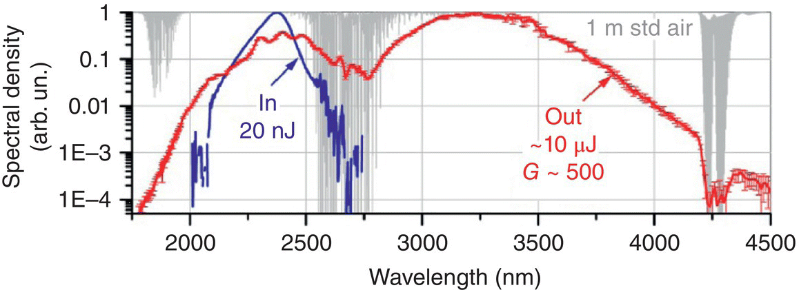
Figure 6.17 SC spectrum, produced in a single‐pass high‐gain (G = 500) Cr:ZnSe amplifier at 1 kHz repetition rate (red curve), along with the spectrum of the input pulses centered at 2.38 μm (blue curve). Shown in gray is the transmission of 1‐m standard air.
Source: reproduced from figure 10 of [54], with permission of OSA, The Optical Society.
With high‐peak‐power 5‐μm femtosecond pump, Ashihara et al. demonstrated a SC spanning 3.5–7 μm (Figure 6.18) in bulk GaAs crystal, taking advantage of its high third‐order Kerr nonlinearity (n2 ≈ 10−17 m2/W) [55]. The λ = 5 μm pulses (corresponding to the normal dispersion regime in GaAs) with 3‐μJ energy and 100‐fs duration were focused into a 10‐mm‐long GaAs crystal (beam diameter 240 μm, propagation direction <110>), such that the peak intensity at the entrance surface was 60 GW/cm2. At half maximum (−3 dB) level, the authors observed the increase of the pump spectral bandwidth by more than four times: from 220 to 910 cm−1. They attributed the main mechanism for broadening to SPM in GaAs. The role of cascaded χ(2) process on SPM was estimated to be small, ~7% of that for the intrinsic Kerr nonlinearity.

Figure 6.18 SC spectrum from bulk GaAs pumped at λ = 5 μm. Input spectrum (dashed) and output spectra (solid) for the pump pulse energies of 1.4 and 2.8 μJ, respectively. Inset shows calculated intensity time profiles of the transform‐limited pulses corresponding to the measured spectra.
Source: reproduced from figure 1 of [55], with permission of OSA, The Optical Society.
Pigeon et al. reported on the generation of an SC from 2 to 20 μm (although with some gaps) in a 67‐mm‐long bulk GaAs crystal pumped by a train of 3‐ps CO2 laser pulses at λ = 10.6 μm (corresponding to the anomalous dispersion regime in GaAs), with 2‐GW peak power and 10‐GW/cm2 incoming peak intensity [56]. Temporal measurements performed by the authors revealed splitting of the original pulse to sub‐picosecond pulses, with harmonic generation, four‐wave mixing, and stimulated Raman scattering being the dominant mechanisms for SC generation.
6.1.7 Other SC Sources
Kartashev et al. reported on a mid‐IR SC generated by filamentation in argon gas. Experiments were performed with an OPCPA system delivering pulses centered at 3.9 μm with up to 12‐mJ energy at 80‐fs duration (peak power > 130 GW), at a repetition rate of 20 Hz. At 4.5‐bar pressure of the argon gas, the authors observed a white‐light beam surrounded by a ring conical emission. The measured spectrum spanned continuously from 0.35 to 5 μm. The filament in argon was measured to be 80 cm in length and 200–300 μm in diameter with a filamentation threshold pressure of around 3.5 bars. The intensity in the filament was estimated to be 45 TW/cm2 [57].
The main results for mid‐IR SC generation are summarized in Table 6.1. Also, a very good overview of experimental results on mid‐IR SC generation can be found in [49].
6.2 Frequency Comb Sources
Frequency combs are typically produced by highly stabilized femtosecond lasers and are characterized by a broad spectrum consisting of evenly spaced, phase‐coherent narrow spectral lines with the spectral width that can be as narrow as a few millihertz [58]. The output of a mode‐locked laser can be regarded as a frequency comb, provided that the laser repetition rate, frep, and the comb offset from zero – the carrier‐envelope offset (CEO) frequency, fCEO – are both stabilized to a high degree of accuracy. (In other words, it is not only that the mode spacing remains constant, but that the absolute position of each mode is fixed as well.) In the time domain, the CEO is directly related to the exact position of the electric field underneath the pulse envelope. This enables generation of optical waveforms with deterministic electric field profile [59]. Extending the operating range of broadband frequency combs to the mid‐IR is critical for a wide range of applications where temporal coherence and reproducibility of the optical field from pulse to pulse play a significant role. These include X‐ray production via high harmonic generation [60], attosecond physics [61], laser‐driven particle acceleration [62], dual‐comb laser spectroscopy [63, 64], and molecular fingerprinting [65].
At the heart of the distinction between a broadband frequency comb and a broadband SC source is the shot‐to‐shot reproducibility of the optical waveform. For example, if a frequency comb is created by spectral broadening in a nonlinear (NL) fiber or a WG, one requirement is that the pulses should remain phase‐stable after the nonlinear process of spectral evolution. The phase‐stability should not be sensitive to the inevitable shot‐to‐shot fluctuations of the drive laser [66]. For example, SPM can be considered to be a deterministic coherence‐preserving process [67], while SC generation due to modulation instability, which is seeded by the random fluctuations of the vacuum field, does not preserve coherence. (One test for phase coherence is whether neighboring pulses show stable interference.) In fact, the SC coherence depends strongly on the duration and wavelength of the input pulse, the length of the WG, and other experimental conditions [5, 66].
In this chapter we will consider several techniques for producing frequency combs including those based on:
- mode‐locked lasers
- frequency conversion using second‐order nonlinearities
- NL fibers and waveguides
- microresonators
- quantum cascade and interband cascade lasers.
An outstanding review by Schliesser et al. [68] surveys different techniques for producing frequency combs in the mid‐IR region, as well as comb applications.
6.2.1 Direct Comb Sources from Mode‐locked Lasers
Thulium‐doped silica fiber lasers operate near λ ≈ 2 μm and mode‐locking in these lasers has been achieved through a variety of techniques (see Chapter 3). Amplifiers based on Tm‐doped fibers can boost the power of these lasers to several watts. Lee et al. have demonstrated a fully stabilized frequency comb at λ ≈ 1.95 μm using a fast intracavity graphene electro‐optic modulator (EOM) [69, 70]. A Tm‐fiber oscillator (Figure 6.19) was pumped at 1564 nm, with a total power 1.3 W. (Additionally up to 10 mW of the pump was provided by a second single‐frequency diode laser, which allowed fast pump modulation.) Stable mode‐locked operation with 100 MHz repetition rate, 20 mW of average output power, was achieved by a saturable‐absorber mirror. Next, the oscillator output was amplified to 200 mW to generate a 1.1–2.4‐μm SC in a highly NL fiber. The CEO frequency, fCEO, was detected by an f−2f interferometer at 1100 nm, involving a PPLN frequency doubling crystal. The fCEO beat was phase‐locked to a stable RF synthesizer via feedback to an intracavity graphene EOM with 5% insertion loss, 2% modulation depth, and 600‐kHz bandwidth (Figure 6.19). Alternatively, fCEO could be locked by fast pump power modulation. Using a slice of the generated SC around 1.55 μm, the laser comb was also phase‐locked to a narrow‐linewidth (3 kHz) optical reference laser near 1.5 μm. This was done by detecting a heterodyne beat between one of the comb teeth and the reference laser, and by phase‐locking it by feedback to the lead zirconate titanate (PZT) piezoelectric actuator cavity‐length control. Generally, state‐of‐the‐art 2‐μm Tm‐fiber frequency comb sources now produce sub‐70‐fs pulses with a bandwidth of 100 nm (260 cm−1) and an average power of 400 mW for comb‐mode spacing 100 MHz, or as high as 2.5 W for comb‐mode spacing 400 MHz [71, 72].
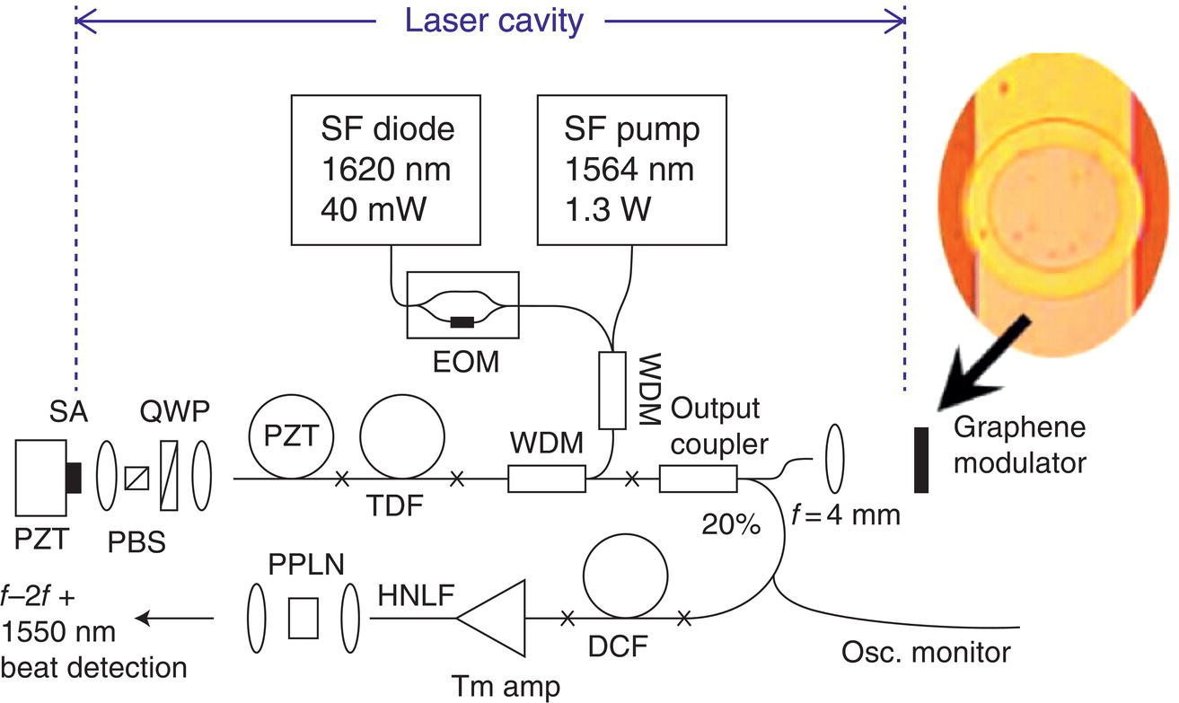
Figure 6.19 Fully stabilized frequency comb based on λ = 2‐μm mode‐locked thulium‐doped silica fiber laser with a graphene modulator. WDM, wavelength division multiplexer; TDF, thulium‐doped fiber; DCF, dispersion compensating fiber; PZT, piezoelectric actuator for repetition rate stabilization; QWP, quarter‐wave plate; PBS, polarization beam splitter; SA, saturable‐absorber mirror; HNLF, highly nonlinear fiber for SC generation; PPLN, periodically poled lithium niobate. The inset is an optical microscope image of the modulator (diameter 280 μm).
Source: reproduced from figure 1 of [69], with permission of OSA, The Optical Society.
A promising class of solid‐state mode‐locked lasers suitable for producing broadband frequency combs is represented by the family of lasers based on transition metal ions such as Cr2+ or Fe2+ doped into group II–VI polycrystals operating correspondingly in the 2–3 and 4–5 μm regions (see Chapter 2). For example, Cr2+:ZnSe and Cr2+:ZnS lasers with center wavelength of 2.3–2.5 μm have broad emission bands exceeding 1000 nm and are regarded as mid‐IR analogs of the Ti:sapphire laser, in terms of extremely broad emission band and high stimulated emission cross section [73]. In addition, these lasers can be conveniently pumped by robust erbium or thulium fiber lasers. A spectral span of 1.9–2.7 μm (bandwidth >1500 cm−1) has been demonstrated from a Kerr‐lens mode‐locked Cr:ZnS oscillator, with pulse duration down to few optical cycles [54]. In a recent paper, Vasilyev et al. reported an octave‐wide (1.6–3.2 μm at −40 dB) span of an Cr:ZnS oscillator emitting few‐cycle pulses with 4‐W average power and 78‐MHz repetition rate [74]. A unique feature of this system is that it enables the intrinsic common‐path nonlinear interferometry: the CEO frequency, fCEO, was detected by observing 3f–4f beat signal in the visible range (~633 nm) with a signal‐to‐noise ratio of 40 dB. The visible signal originated directly from the laser resonator, with the frequency beats being the result of interfering the broadband third and fourth harmonics of the mid‐IR spectrum, both produced via random phase‐matching in the Cr:ZnS polycrystal – a χ(2) material. A fully referenced Cr:ZnS optical frequency comb has been reported in [75].
There is also ongoing research into ultrafast Er3+‐doped fluoride glass fiber lasers operating at longer (~3 μm) wavelengths that can potentially serve as frequency combs [76] (see Chapter 3).
6.2.2 Combs Produced by Spectral Broadening in NL Fibers and Waveguides
Generation of a broadband SC in a fiber pumped by a phase‐coherent laser does not guarantee obtaining a phase‐coherent frequency comb owing to the excess noise produced during SC generation. To ensure that the coherence is preserved, it is important to use a short (a few cm) piece of NL fiber in combination with short (~100 fs or less) laser pulses. Using a highly nonlinear fiber (HNLF) consisting of a small‐effective‐area (~14 μm2) dispersion‐flattened germanium‐doped silica fiber, Washburn et al. [77, 78] demonstrated a phase‐locked frequency comb spanning from 1100 to 2200 nm. The pump was a mode‐locked erbium‐doped fiber laser at 1.55 μm with an average power of 100 mW and 70‐fs pulse duration. The SC output was a frequency comb with both spacing and CEO frequency that was set by the pump laser. The coherence of the comb has been proven by detecting frequency beats using the f‐to‐2f heterodyne technique.
Marandi et al. have studied coherence properties of the 2.2–5 μm SC that was produced in an 18‐mm‐long tapered As2S3 fiber by pumping it at λ ≈ 3.1 μm (a subharmonic of a femtosecond 1.56‐μm Er‐fiber laser; see also Section 6.1.4) [30]. To verify that the broad mid‐IR SC output preserves the frequency comb structure of the laser, the frequency‐doubled SC was interfered with a continuous‐wave (CW) narrow‐linewidth (3 kHz) laser at 1564 nm and the beat frequency was measured. Another beat frequency signal was obtained by interfering the mode‐locked Er‐fiber laser and the CW laser. The two beat frequencies were the same and tracked each other during tuning of the CEO frequency of the Er‐fiber laser. This verified that the coherence of the 1.56‐μm pump was preserved through the two frequency downconversion processes: (i) subharmonic generation in a subharmonic OPO and (ii) subsequent spectral broadening in the tapered fiber.
Generation of a phase‐coherent broadband 1.8–3.8 μm SC was reported in an As2S3 WG embedded in silica [79]. The nonlinear WG consisted of a tapered silica capillary filled with As2S3. To create this structure, melted chalcogenide glass was pushed into the capillary by pressurized argon. The device was only 2 mm long with the first 0.3 mm being a tapered region. The untapered region had an inner diameter of 1 μm (Figure 6.20a) and the two ZDWs were at 1.35 and 2.5 μm. The pump pulses from a 2‐μm Tm‐doped fiber laser (pulse duration 65 fs, repetition rate 100 MHz) were launched into the WG from the tapered side, such that the incident light was transformed adiabatically into the fundamental mode of the As2S3 WG with a coupling efficiency of ~12%. Soliton fission and dispersive wave generation along the uniform section resulted in spectral broadening out to almost 4 μm (Figure 6.20b) for launched energies of only 18 pJ (the total pump average power used was 7 mW). In another experiment, coherence properties of the SC produced in this “nanospike” WG were tested. The pump was a fully stabilized 2‐μm Tm‐fiber frequency comb. A portion of the nanospike SC near λ = 3.3 μm was combined with the corresponding portion of the output of an OP‐GaAs OPO that was itself coherent with the shared pump laser. A strong interference (a radiofrequency beat note) between the SC and the OPO output showed that SC generation in the WG was coherence‐conserving [80].
Kuyken et al. used an SOI WG to generate a phase‐coherent broadband frequency comb. As in the previous example, the comb generator required low pump power; it had a 30‐dB bandwidth spanning from 1.54 to 3.2 μm [81]. A 1‐cm‐long air‐clad photonic wire grown on top of a buried oxide layer had a rectangular cross section of 1600 × 390 nm. The pump source was tuned to 2.29 μm, close to the ZDW of the WG (2.18 μm), and delivered 35 mW of average power at 100 MHz repetition rate and 70‐fs pulse duration. The broad spectrum was obtained with a coupled pulse energy of as low as 16 pJ. Coherence of the SC was confirmed by beat note measurements with a set of narrow linewidth CW lasers. The authors argue that the use of short pulses favored dispersive wave generation and SPM that maintain the coherence in the pump.

Figure 6.20 (a) Chalcogenide nanospike embedded in silica; light enters from the tapered side on the left. (b) Broadband spectrum of the supercontinuum produced after propagating along the chalcogenide‐silica waveguide (sample length 1.7 mm).
Source: reproduced from figure 6 of [79], with permission of OSA, The Optical Society.
6.2.3 Combs Produced by Difference Frequency Generation
DFG is a widespread method of producing frequency combs in the mid‐IR. Thanks to the coherent nature of the three‐photon process, coherence of a near‐IR pump comb is directly transferred to the mid‐IR. For example, DFG can be performed by mixing outputs of a mode‐locked and a CW laser. In this way, by mixing a 1.56‐μm comb with a stable CEO frequency with the output of a tunable (1030–1070 nm) CW laser in a PPLN crystal, Maddaloni et al. created a new comb with central wavelength ranging from 2.9 to 3.5 μm with an instantaneous wavelength span of 180 nm and an average power of 5 μW [82].
Galli et al. presented a highly coherent mid‐IR comb produced through an intracavity DFG process [83]. The output of a mode‐locked Ti:sapphire laser was first spectrally broadened to 500–1100 nm by a PCF. The 1040‐nm portion of this spectrum was amplified in an Yb‐doped fiber and then mixed with the intracavity radiation inside the mode‐locked Ti:sapphire laser, using a MgO:PPLN nonlinear crystal. A mid‐IR comb was generated with an average power of 0.5 mW and 2‐kHz tooth linewidth. The generated spectrum spanned 27 nm, with a center wavelength tunable from 4.2 to 5 μm. Also, the high repetition rate (1 GHz) ensured high spectral brightness (1 μW per comb tooth) [83].
High efficiency can be achieved in a DFG process that uses two phase‐coherent amplified pulse trains that originate from the same oscillator [84–89]. In such a process, one of the pulse trains is frequency red‐ or blueshifted in an NL fiber. The mid‐IR pulse train in this DFG scenario is expected to exhibit a “harmonic” comb structure (fCEO = 0) as a result of the cancelation of CEO frequencies by subtracting frequencies of the two near‐IR combs.
Erny et al. [84] generated mid‐IR frequency combs by performing DFG between the outputs of two near‐IR sources coherently linked to the same femtosecond mode‐locked fiber oscillator. The oscillator (Figure 6.21a) seeded two separate amplifier stages, each delivering 65‐fs pulses centered at ~1.58 μm with an average power of 250 mW and a repetition rate of 82 MHz. The output of the second amplifier was coupled into a highly nonlinear fiber (HNLF, core diameter of 3.7 μm, ZDW ~1.52 μm). The HNLF output was tunable near λ ≈ 1 μm and was compressed with a prism pair to sub‐40‐fs duration. By nonlinear mixing of 1.58‐μm pulses (average power 170 mW) with near‐infrared pulses tunable between 1.05 and 1.18 μm (average power 11.5 mW) in a 2‐mm‐long PPLN crystal, the authors achieved femtosecond pulses tunable in the 3.2–4.8 μm range (Figure 6.21b) with an average power of 1.1 mW.
Using the same strategy of mixing the outputs of two near‐IR fiber amplifiers (Yb‐doped and Er‐doped) seeded by the same oscillator, several groups have reported high‐power (>100 mW) mid‐IR frequency combs with the spectrum coverage 3–4.4 [85], 2.9–3.6 [86], and 2.3–3.6 μm [87]. Using a 3‐mm‐long MgO:PPLN crystal, Cruz et al. produced mid‐IR femtosecond frequency combs with the average power 530 mW (3 μW/mode at 100‐MHz mode spacing) with a spectral covering of 2.8–3.5 μm [88]. Also, Maser et al. demonstrated a dual‐comb DFG system suitable for mid‐IR molecular spectroscopy. The center wavelength was tunable between 2.6 and 5.2 μm with an instantaneous bandwidth of 33–230 cm−1 [89].

Figure 6.21 (a) Experimental DFG setup of [84]. FLO, fiber‐laser oscillator; FLA1 and FLA2, fiber‐laser amplifiers; HNLF, highly nonlinear fiber; LN, MgO‐doped PPLN nonlinear crystal. (b) Normalized mid‐IR DFG spectra.
Source: reproduced from figures 1 and 2 of [84], with permission of OSA, The Optical Society.
Through DFG in a 1‐mm‐long orientation‐patterned gallium phosphide (OP‐GaP) with multiple grating periods, Lee et al. generated frequency combs with the center wavelength varying from 6 to 11 μm, with 350–400 cm−1 instantaneous frequency span and up to 60 mW average power [90]. The DFG “pump” and “signal” waves were correspondingly the outputs of erbium and thulium fiber amplifiers seeded by the same erbium‐fiber mode‐locked oscillator, whose repetition rate was tightly stabilized to ~1 Hz by optical referencing to a narrow‐linewidth diode laser.
DFG frequency combs with long‐wavelength (>10 μm) coverage were attained with GaSe as a frequency mixer, thanks to its broad transparency range (0.6–20 μm) combined with high optical nonlinearity [91–94]. An extremely broad tuning of 4–17 μm, which covers most of the infrared “fingerprint” molecular vibration region, was reported by Keilmann and Amarie [94]. The mixing occurred in a 1‐mm‐long angle‐tuned GaSe crystal. As a pump, the authors used amplified femtosecond pulses at 1.55 μm and SC pulses in the 1.7–2.3 μm region produced in a nonlinear optical fiber (Figure 6.22a). The near‐IR SC was spectrally tuned by changing the chirp of the driving 1.55‐μm pulses, and this tuned the spectrum of the DFG pulses. The resulting broadly tunable mid‐IR harmonic frequency comb had an instantaneous spectral width of approximately 700 cm−1 (at –20 dB level, Figure 6.22b) and an average power of 1 mW [94].
Another way for generating longwave infrared (LWIR, 5–20 μm) frequency combs is through intra‐pulse DFG (optical rectification, see Section ). Timmers et al. presented a robust method for generating super‐octave spanning LWIR frequency combs through intra‐pulse DFG driven by spectrally broadened and compressed few‐cycle pulses with 10.6‐fs duration from an erbium fiber system [65]. Because LWIR modes occur as a difference between the n‐th and m‐th pump modes (m and n are integers), the CEO frequency of the pump is subtracted out. This provides an offset‐free (harmonic) LWIR comb consisting of exact harmonics of the laser repetition frequency, νk = kfrep, where k is an integer. For frequency self‐mixing, the authors used a 1‐mm‐thick OP‐GaP crystal. With the pump power of 350 mW, they produced a frequency comb spanning 4–12 μm with 0.25 mW of the average power [65].
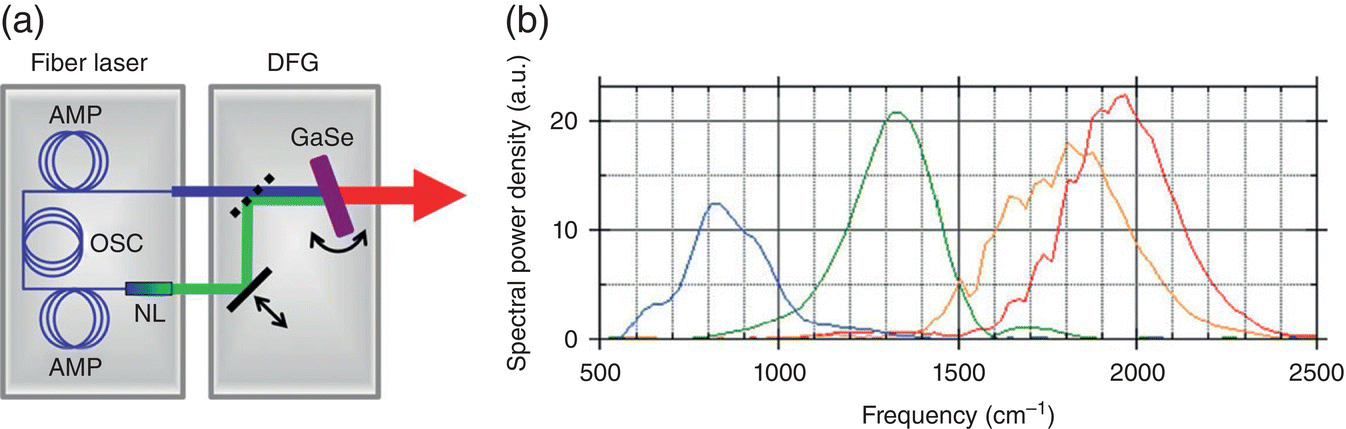
Figure 6.22 (a) Schematics of the long‐wavelength mid‐IR comb source [94]. The fiber laser system contains a common oscillator (OSC), two amplifiers (AMP), and a nonlinear optical fiber (NL) producing a redshifted near‐IR continuum. The DFG unit combines both free‐space output beams at zero pulse delay in a GaSe crystal which generates the mid‐IR beam. (b) Corresponding DFG spectra.
Source: reproduced from figures 1 and 2 of [94], with permission of Springer.
The main results on DFG combs are summarized in Table 6.2.
6.2.4 OPO‐based Combs
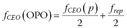
An OPO needs only one pump laser, and typically provides much higher conversion efficiency and much higher average power, as compared to DFG. This comes at the expense of a more delicate setup that includes a stabilized synchronously pumped (“sync‐pumped”) resonant cavity. While the OPO automatically inherits the repetition rate of the pump laser, a fixed CEO frequency of the pump does not automatically guarantee that the CEO frequencies of the OPO “signal” and “idler” waves are fixed. The photon energy conservation law just connects the three CEO frequencies in the following way:
where “p,” “s,” and “i” stand for pump, signal, and idler waves. The corresponding angular frequencies ωp, ωs, and ωi are related (again, through the photon energy conservation law) as ωp = ωs + ωi. Thus, a separate CEO frequency control is required for the OPO waves.
Sun et al. produced a frequency comb ranging from the violet to the mid‐infrared (0.4–2.4 μm) by phase locking a pump laser and a sync‐pumped OPO to a common reference [118]. The mode‐locked Ti:sapphire 800‐nm pump laser (1.3 W average output power, 50‐fs pulse duration) was repetition‐rate locked to an external 200‐MHz clock and part of its power was launched into a 30‐cm PCF to generate an SC to stabilize the laser CEO frequency via f‐to‐2f interferometry. The main laser output was used to pump the OPO, based on MgO‐doped PPLN with the signal output tunable from 1.2 to 1.37 μm and the idler from 2.4 to 1.9 μm. By using the OPO combinational outputs at frequencies 2ωs (red) and ωp + ωi (yellow) and measuring beat notes with the common SC reference, the OPO comb was CEO frequency locked through the use of a piezoelectric transducer (PZT) mounted on an OPO cavity end mirror.
Adler and coauthors reported on a high‐power (~1.5 W) fully stabilized OPO mid‐IR comb [95, 119]. The linear‐cavity OPO was synchronously pumped by a 10‐W femtosecond Yb‐fiber laser centered at 1.07 μm and employed a 7‐mm PPLN crystal with a variable poling period. The OPO idler wave was tunable from 2.8 to 4.8 μm with an instantaneous bandwidth of ~300 nm. The OPO comb stabilization was done by exploiting (as in the previous example) parasitic mixing signals in the visible (ωp + ωs) and near‐IR (ωp + ωi) produced inside the OPO cavity, that were superimposed with a broad SC generated by a portion of the pump laser output in a PCF. Since the SC has fCEO corresponding to that of the pump laser, the observed heterodyne beats corresponded to fCEO(s) and fCEO(i). Typically, fCEO(s) was locked to a stable RF reference via stabilizing the OPO cavity length with a piezo‐actuated end mirror. On the other hand, fCEO(i) was stabilized via the relation (6.1) by feeding the error signal back to the fiber laser pump diode power, which acts on fCEO(p). The maximum idler power of ~1.5 W was obtained at 3.2 μm center wavelength, whereas the highest photon conversion efficiency (51%) was observed at 3.6 μm. The typical OPO idler spectra are shown in Figure 6.23.
Table 6.2 Summary of mid‐IR frequency combs.
| Method | Pump source | Instantaneous comb span | Ave. power | Mode spacing | Ref. |
| Direct mode‐locked laser combs | |||||
| Mode‐locked Tm fiber laser | CW Er‐fiber | 1.9–2.0 μm | 2.5 W | 418 MHz | [72] |
| Kerr‐lens mode‐locked Cr:ZnS laser | CW Er‐fiber | 1.79–2.86 μm | 3.25 W | 80 MHz | [75] |
| Kerr‐lens mode‐locked Cr:ZnS laser | CW Er‐fiber | 1.6–3.2 μm | 4.1 W | 78 MHz | [74] |
| Combs based on SC generation | |||||
| Nanospike As2S3 waveguide in silica, L = 1.7 mm | 2 μm, 65 fs, 7 mW, 1 kW peak | 1.8–3.7 μm | 1.8 mW | 100 MHz | [79] |
| Si waveguide, L = 10 mm | 2.3 μm, 70 fs, 35 mW, 230 W peak | 1.54–3.2 μm | 1.6 mW | 100 MHz | [81] |
| DFG combs | |||||
| DFG, PPLN | CW 1.03–1.07 μm (0.7 W),fs 1.56‐μm (0.7 W) | 180 nm, tune 2.9–3.5 μm | 5 μW | 100 MHz | [82] |
| Resonant DFG, PPLN | fs 0.8‐μm (30 W intracavity),fs 1‐μm SC | 27 nm, tune 4.2–5 μm | 0.5 mW | 1 GHz | [83] |
| DFG, PPLN | fs 1.05–1.18 μm SC (11 mW),fs 1.58 μm (170 mW) | 500 nm, tune 3.2–4.8 μm | 1.1 mW | 82 MHz | [84] |
| DFG, PPLN | fs 1‐μm + fs 1.5‐μm Raman (2.4 W total) | 170 nm, tune 3–4.4 μm | 128 mW | 100 MHz | [85] |
| DFG, PPLN | fs 1.55 μm (450 mW), fs 1.05 μm SC (1.2 W) | 2.9–3.6 μm | 120 mW | 250 MHz | [86] |
| DFG, PPLN | fs 1.04 μm (1.4 W), fs 1.55 μm (400 mW) | 750 nm, tune 2.3–3.6 μm | 150 mW (3.1 μm) | 100 MHz | [87] |
| DFG, PPLN | fs 1.06 μm (4 W), fs 1.55 μm (140 mW) | 700 nm, tune 2.8–3.5 μm | 530 mW (3 μm) | 100 MHz | [88] |
| DFG, PPLN dual comb | fs 1‐μm SC (735 mW), fs 1.3–1.5‐μm SC (81 mW) | 33–230 cm−1, tune 2.6–5.2 μm | 20 mW (3.5 μm) | 100 MHz | [89] |
| DFG, OP‐GaP | fs 1.55 μm (1.6 W), fs 1.8–2.1 μm (0.6 W) | 35–400 cm−1, tune 6–11 μm | 60 mW (8 μm) | 93 MHz | [90] |
| DFG, GaSe | fs 1.55 μm (250 mW), fs 1.75–1.95 μm SC | 200 cm−1, tune 5–12 μm | 160 μW (6.3 μm) | 100 MHz | [91] |
| DFG, GaSe | fs 1.55 μm (550 mW), fs 1.76–1.93 μm SC(250 mW) | ~300 cm−1, tune 8–14 μm | 4 mW (7.8 μm) | 250 MHz | [92] |
| DFG, GaSe | fs 1.055 μm (1.9 W), fs 1.18–1.63 μm SC (20 mW) | ~300 cm−1, tune 3–10 μm | 1.5 mW (4.7 μm) | 151 MHz | [93] |
| DFG, GaSe | fs 1.5 μm (360 mW), fs 1.7–2.3 μm SC (160 mW) | ~700 cm−1, tune 4–17 μm | 1 mW | 40 MHz | [94] |
| Self‐mixing, OP‐GaP | 10.6 fs, 1.56 μm, 350 mW | 4–12 μm | 0.25 mW | 100 MHz | [65] |
| OPO combs | |||||
| PPLN OPO | fs Yb‐fiber, 1.07 μm, 10 W | 300 nm, tune 2.8–4.8 μm | 1.5 W | 136 MHz | [95] |
| PPKTP OPO | 20‐fs, Ti:Sapph.,0.8 μm, 1.4 W | 200 nm, tune 0.4–3.2 μm | ~mW | 100 MHz | [96] |
| PPLN OPO | Chirped 3‐ps, Yb‐fiber, 1.05 μm, 2.2 W | 200 nm, @ 3.6 μm | 144 mW | 94 MHz | [97] |
| PPLN OPO | fs, Yb‐fiber, 1.04 μm, 5 W | 300 nm, tune 2.25–4 μm | 160 mW | 51 MHz | [98] |
| PPLN OPO | fs, Yb‐fiber, 1.04 μm, 2 W | 350 nm, tune 2.7–4.7 μm | 250 mW | 90 MHz | [99, 100] |
| PPLN OPO | fs, Er‐fiber, 1.56 μm, 580 mW | 100–200 nm, tune 2.25–2.6 and 4.1–4.9 μm | 20–60 mW | 250 MHz | [101] |
| AgGaSe2 OPO | fs, Tm‐fiber, 1.95 μm, 2.5 W | 500–700 nm, tune 8.4–9.5 μm | 100 mW | 110 MHz | [101] |
| Subharmonic OPO combs | |||||
| PPLN OPO | fs Er‐fiber, 1.56 μm,300 mW | 2.5–3.8 μm | 60 mW | 100 MHz | [102] |
| OP‐GaP OPO | fs Er‐fiber, 1.56 μm,300 mW | 2.35–4.8 μm | 29 mW | 100 MHz | [103] |
| OP‐GaAs OPO | fs Tm‐fiber, 1.93 μm, 330 mW | 2.6–7.5 μm | 75 mW | 115 MHz | [104] |
| OP‐GaAs OPO | fs Cr:ZnS, 2.35 μm,650 mW | 2.85–8.4 μm | 110 mW | 80 MHz | [105] |
| OP‐GaAs OPO | fs Cr:ZnS, 2.35 μm, 6 W | 3–8 μm | 500 mW | 900 MHz | [106] |
| OP‐GaP OPO | fs Cr:ZnS, 2.35 μm, 1.2 W | 3–12.5 μm | 31 mW | 79 MHz | [107] |
| Microresonator combs | |||||
| SiO2 toroid | 1.56 μm, 2.5 W | 1–2.17 μm | — | 850 GHz | [108] |
| SiN microring | 1.56 μm, 2 W | 1.17–2.35 μm | — | 226 GHz | [109] |
| Si waveguide resonator | CW OPO, 2.59 μm, 1.2 W, 100 kHz linewidth | 2.1–3.5 μm | — | 127 GHz | [110] |
| Si waveguide resonator | CW OPO, 2.6 μm, 180 mW | 2.46–4.28 μm | — | 127 GHz | [111] |
| MgF2 microresonator | CW OPO, 2.45 μm, 600 mW | 2.35–2.55 μm | — | 107 GHz | [112] |
| MgF2 disk | QCL, 4.4 μm, 80 mW | 4.16–4.76 μm | — | 14.3 GHz | [113] |
| MgF2 disk | QCL, 4.5 μm, 55 mW | 3.7–5.5 μm | — | 2100 GHz | [114] |
| QCL combs | |||||
| InGaAs/InAlAs | Electric current | 6.8–7.3 μm | Few milliwatts | 7.5 GHz | [115] |
| InGaAs/InAlAs | Electric current | 110 cm–1 @ 8 μm | 880 mW | 11.2 GHz | [116] |
| ICL combs | |||||
| InAs/GaInSb/AlSb | Electric current | 35 cm−1 @ 3.6 μm | ~6 mW | 9.7 GHz | [117] |
Iwakuni et al. produced a long‐wavelength phase‐stabilized frequency comb in a synchronously pumped, singly resonant OPO, based on an angular phase‐matched AgGaSe2 crystal [120]. The pump laser was a mode‐locked Tm:fiber laser at 1.95 μm, with a repetition rate of 110 MHz, and a maximum output power of 2.5 W. The OPO was continuously tuned, with the center wavelength range of 8.4–9.5 μm (instantaneous bandwidth 500–700 nm) and a maximum average idler power of 100 mW at λ ≈ 8.5 μm. Both the repetition rate and the CEO frequency of the idler wave were phase‐locked to microwave signals referenced to a Cs clock. The CEO of the idler wave was achieved by stabilizing the heterodyne optical beat of the sum frequency of the pump and idler wave (ωp + ωi), parasitically produced in the OPO cavity, and spectrally broadened pump wave (ωp) using a highly nonlinear fiber.
Results for other frequency comb sources based on singly resonant OPOs pumped by Ti:sapphire [96], Yb‐fiber [97–100], and Er‐fiber lasers [101] are summarized in Table 6.2. The reader can find a very good review paper on frequency combs based on femtosecond OPOs in [121].

Figure 6.23 Typical PPLN‐based OPO idler comb spectra of [95], normalized and vertically offset.
Source: reproduced from figure 3 of [95] with permission of OSA, The Optical Society.
6.2.5 Combs Based on Optical Subharmonic Generation
A new method was implemented, suitable for generating extremely broadband mid‐IR coherent outputs based on a degenerate (subharmonic) sync‐pumped OPO [102, 122, 123]. A schematic of such an OPO is shown in Figure 6.24. The bottom panel displays, from top to bottom, the evolution of the spectrum when the OPO is driven from a nondegenerate to a partly degenerate, and finally to a degenerate (subharmonic) regime. In the last case, the co‐polarized signal and the idler modes become indistinguishable, which results in some interesting properties.
For example, the subharmonic OPO source rigorously both down‐converts (from the center frequency ωp to the center frequency ωp/2) and dramatically augments the spectrum of a pump frequency comb provided by a mode‐locked pump laser. The key advantages of the degenerate OPO approach are: (i) low pump threshold (typically ~10 mW) owing to the double (signal and idler) resonance, (ii) potential for high conversion efficiency (>50%) due to a non‐dissipative nature of three‐wave processes and recycling of all the generated photons, (iii) broad gain bandwidth at the OPO degeneracy, and (iv) phase locking to the pump laser (a subharmonic OPO can be considered as an ideal coherent frequency divider). These advantages come at the expense of the interferometric sensitivity of the cavity length alignment, owing to the double resonance. However, the cavity length can be actively stabilized, e.g. via the “dither‐and‐lock” method [102] involving a piezo actuator mounted on one of the OPO mirrors.
In simple terms, when the co‐polarized signal (s) and the idler (i) waves become indistinguishable at degeneracy, fCEO(s) = fCEO(i) = fCEO(OPO) and Eq. (6.1) reduces to the two deterministic solutions [122]:

The two solutions toggle when one toggles between adjacent cavity lengths (spaced by approximately pump wavelength, in terms of the cavity roundtrip length) that fulfill the doubly resonant condition [122]. In a similar way, a deterministic phase relation between any mode of the OPO and that of the pump is established through the usual relation for a three‐wave nonlinear conversion process (for simplicity, the mode indices were omitted):
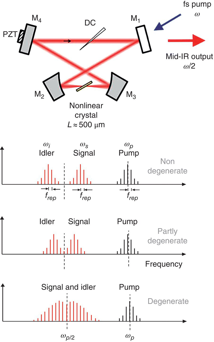
Figure 6.24 (Top) Schematic of a ring‐cavity sync‐pumped subharmonic OPO. M1, dielectric mirror for in‐coupling of the pump; M2 and M3, concave, gold‐coated mirrors; M4, flat, gold‐coated mirror; DC, dispersion compensating wedge made of a suitable dielectric; PZT, piezo actuator for fine‐tuning the cavity length. (Bottom) Conceptual sketch showing evolution of the spectrum when the OPO is driven (from top to bottom) from a nondegenerate to partly degenerate to degenerate (subharmonic) regime.
Since ϕs = ϕi (=ϕOPO), any mode of the OPO becomes phase‐locked to that of the pump through the relation:
A variety of ultrafast lasers with central wavelengths varying from 1.5 to 2.5 μm, in combination with different χ(2) nonlinear materials, such as PPLN, OP‐GaAs, and OP‐GaP, were used to achieve broadband mid‐IR combs by subharmonic generation in sync‐pumped OPOs [102, 103, 124, 125]. The first system of this kind producing a broadband mid‐IR output was based on a PPLN crystal pumped by a mode‐locked 1.56‐μm Er‐fiber laser (repetition frequency 100 MHz, pulse duration 70 fs, average power 300 mW). Low intracavity dispersion and large parametric gain bandwidth at degeneracy, associated with the use of a short (0.2–0.5 mm) PPLN crystal, combined with extensive cross‐mixing of comb components, resulted in an instantaneous mid‐IR bandwidth of 2.5–3.8 μm, with up to 60 mW of the average power [102]. This bandwidth was extended to an octave‐wide (2.35–4.8 μm) with the use of the same pump laser and an OP‐GaP as an OPO gain element [103]. (As compared to PPLN, OP‐GaP has deeper IR transparency and smaller mid‐IR GVD, which resulted in the achievement of a larger bandwidth.) The use of orientation‐patterned GaAs (OP‐GaAs) crystal as a nonlinear gain medium, combined with a mode‐locked Tm‐fiber laser frequency comb as a pump (center wavelength 1.93 μm, pulse duration 90 fs, repetition rate of 115 MHz, average power 330 mW) enabled a highly coherent comb, spanning 2.6–7.5 μm [104]. The pump threshold was as low as 7 mW and the output average power reached 73 mW at the full pump power. Figure 6.25 depicts the frequency comb spectrum measured with an FTIR spectrometer.
Ultrafast Cr2+:ZnSe and Cr2+:ZnS lasers operating near 2.4 μm (see Chapter 2) are extremely well suited for producing subharmonic combs in OP‐GaAs and OP‐GaP crystals, thanks to their small GVD near half the frequency of the pump (at ~4.8 μm) [105, 106, 126]. An instantaneous spectral span of 2.85–8.40 μm was achieved in a subharmonic OP‐GaAs OPO pumped at 2.35‐μm central wavelength with 62‐fs pulse duration, 800‐mW average power, and 79‐MHz repetition rate. The OPO threshold was 8 mW and the maximum average output power reached 110 mW [105]. When the OPO was pumped at high (0.9 GHz) repetition frequency with 6‐W average power and 77‐fs pulse duration, the emitted average power reached 500 mW with a spectral span of 3–8 μm [106]. Even broader spectral span, exceeding two octaves (3–12.5 μm), was achieved with the use of the OP‐GaP crystal (pump at 2.35 μm, repetition rate 79 MHz, average power 1.2 W, pulse duration 62 fs) [107]. So far, only free‐running broadband combs have been achieved with subharmonic 2.35‐μm pumped OPOs, since the fCEO of the pump combs was not stabilized.
Coherence properties of subharmonic OPOs were studied in detail in [72, 103, 104, 127, 128]. Sub‐Hz relative linewidths of the comb teeth with respect to the pump laser were experimentally demonstrated, as well as the absence of excess phase noise in the process of frequency division. Thus, subharmonic generators serve as ideal coherent frequency dividers for generating low‐noise mid‐IR combs.
The main results of the subharmonic OPO combs are summarized in Table 6.2.

Figure 6.25 Frequency comb spectrum from a Tm‐fiber laser pumped (1.93 μm) subharmonic OPO based on OP‐GaAs crystal. The spectral span is 2.6–7.5 μm (−20 dB level). The vertical dotted line is the OPO degeneracy (3.86 μm). The dashed line is the calculated extra phase accumulated per round trip due to group velocity dispersion. The top panel shows the simulated transmission through 2.6 m (cavity round‐trip length) of purged (5% humidity) air.
Source: reproduced from figure 5 of [104], with permission of OSA, The Optical Society.
6.2.6 Microresonator‐based Kerr Combs
Another new principle for optical frequency comb generation, “Kerr combs” [129, 130], uses parametric frequency conversion based on the third‐order optical nonlinearity χ(3) in whispering gallery mode resonators with high resonance quality (Q) factors. In such resonators, represented by microdisks, microspheres, microtoroids, and microrings, the light is confined by the total internal reflection around the perimeter of an air–dielectric or clad–dielectric interface, and extremely high Q‐factors (>108) can be achieved. An optical microresonator is pumped with a narrow‐linewidth CW laser; if the laser frequency is tuned to one of the cavity modes, the resonantly enhanced intensity reaches GW/cm2 levels with modest (milliwatts to watts) optical pump powers. This gives rise to the four‐wave mixing (parametric frequency conversion) also referred to as optical hyper‐parametric oscillation [131, 132] that originates from the Kerr effect – an intensity‐dependent refractive index, n = n0 + n2I. The parametric frequency conversion annihilates two pump photons with angular frequency ωp and creates a new pair of photons – a frequency upshifted signal ωs, and a frequency downshifted idler ωi in the following process:
Or, in a pump nondegenerate case:
This frequency conversion mechanism can lead to a vast cascading of evenly spaced oscillating frequencies, as illustrated in Figure 6.26. If the signal and idler frequencies coincide with optical microresonator modes, the parametric process is enhanced, resulting in efficient spectral broadening. However, for this to happen, the dispersion of the microresonator needs to be properly adjusted in order to satisfy the phase‐matching condition. As compared to frequency combs based on mode‐locked lasers, microresonator‐based combs have much larger line spacing – typically in the range 10–1000 GHz.
Microresonator‐based frequency comb sources pumped by CW lasers have been reported at telecom wavelengths in a number of platforms, including silica [129], high‐index‐doped silica glass [133], crystalline calcium fluoride [134, 135], silicon nitride [136], aluminum nitride [137], and diamond [138].
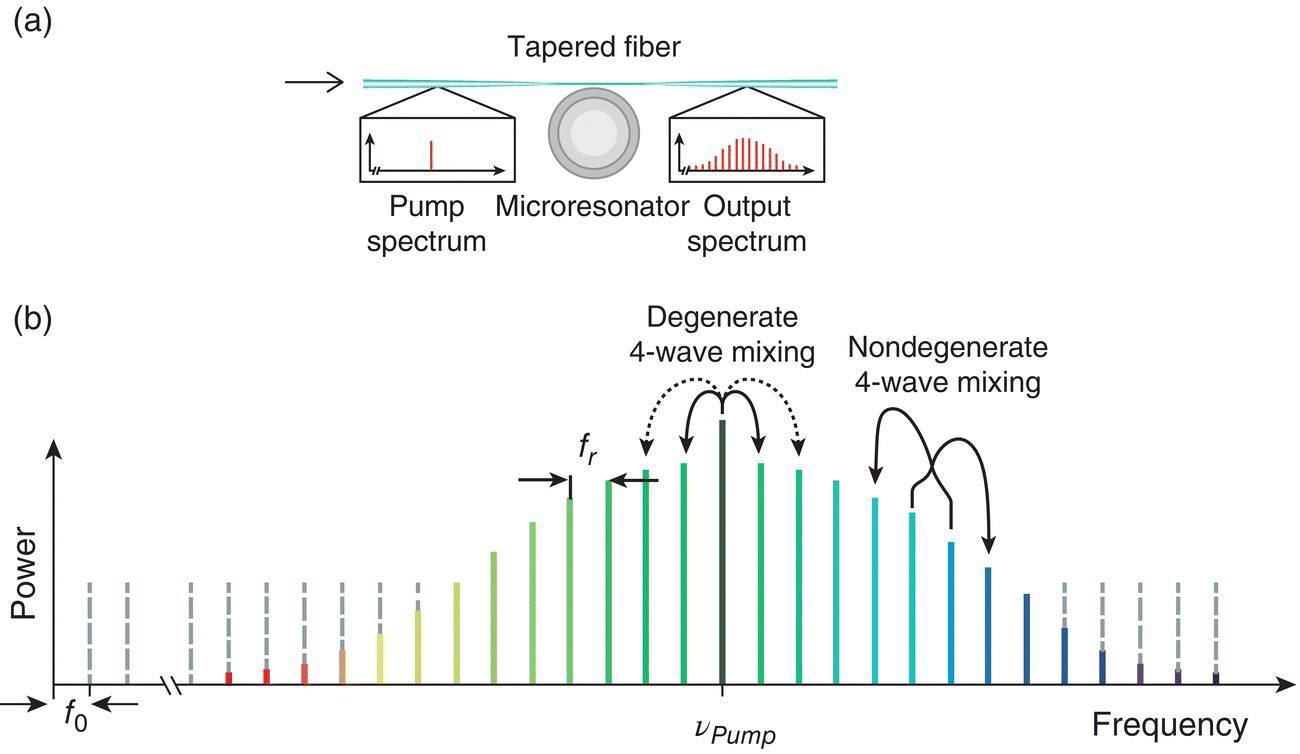
Figure 6.26 Frequency comb generation using microresonators. (a) An optical microresonator is pumped with a CW laser. The high intensity in the resonator (~GW/cm2) gives rise to a parametric frequency conversion. (b) Optical frequency comb is characterized by the repetition rate (fr) and the carrier envelope frequency (fo). The comb is generated by a combination of degenerate and nondegenerate four‐wave mixing.
Source: adapted from figure 2 of [130], with permission of the American Association for the Advancement of Science.
Del'Haye et al. [108] reported the generation of an octave‐spanning optical frequency comb reaching mid‐IR in a CW laser pumped toroidal fused silica microresonator. The output of the pump laser (1560‐nm diode laser amplified to 2.5 W) was coupled to a microresonator mode using a tapered optical fiber. The fused silica microresonator had a radius of 40 μm, and a cross‐section radius of 2.8 μm (Figure 6.27a), mode spacing of 850 GHz, and optical quality factor Q = 2 × 10⁸. The generated comb spectrum (Figure 6.27b) covered the whole range from 1 to 2.17 μm. The ability to generate octave‐spanning combs was attributed by the authors to the optimized (via adjusting the cross section) resonator GVD.
Generation of optical frequency combs from a CMOS‐compatible integrated silicon nitride (Si3N4) microresonator was demonstrated in [109, 139]. Both the microresonator and the coupling WG were fabricated monolithically in a single silicon nitride layer using electron‐beam lithography and subsequently clad with silica. The 112‐ or 200‐μm‐radius microring resonator (Figure 6.28a) had a free‐spectral range of 204 or 226 GHz, and a quality factor Q > 105. The cross‐sectional dimensions of both the coupling WG and the ring (750 nm in height and 1500 nm in width) were designed to produce anomalous GVD at the pump wavelength of 1550 nm. Up to 2 W of power from an amplified tunable diode laser were injected into the coupling WG. As the pump laser was tuned into resonance, cascaded four‐wave mixing generated new frequencies with the comb span from 1.17 to 2.35 μm (Figure 6.28b). Also, it has been verified in this work that the mode equidistance is better than 3 × 10⁻¹⁵ relative to the center comb frequency [139].
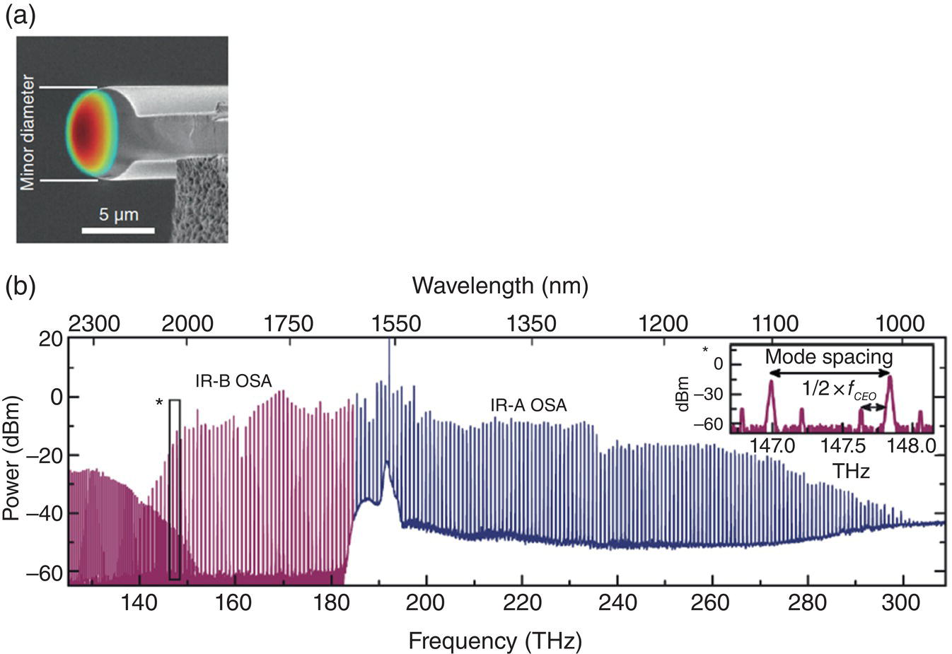
Figure 6.27 (a) Scanning electron microscope image of a cleaved fused silica microresonator (also shown is a simulated mode profile). (b) Frequency comb, generated in a 40 μm‐radius silica microresonator with the modal spacing of 850 GHz. The feature on the low‐frequency side (<140 THz) is a spectrometer artifact due to second‐order diffraction.
Source: reproduced from figure 1 of [108], with permission of APS.
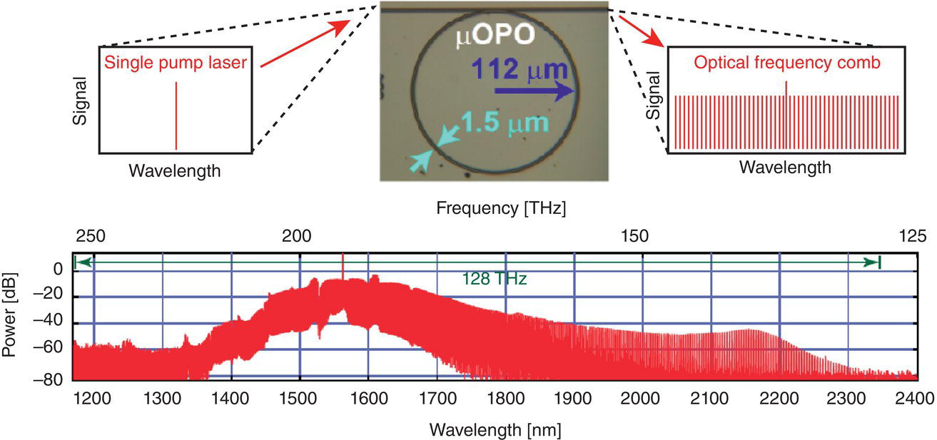
Figure 6.28 Schematic of a CMOS‐compatible silicon nitride microresonator and experimentally measured frequency comb spectrum.
Source: adapted from figure 2 of [139], with permission of OSA, The Optical Society.
With a microring resonator made of a Si3N4 WG with silica cladding and 2.6‐μm pump (an OPO output), Luke et al. demonstrated a comb with a free spectral range of 99 GHz and a wavelength span of 2.3–3.5 μm (at −60 dB level). The ring resonator had the radius 230 μm, the WG cross section 950 by 2700 nm, and the gap between the ring and the coupling WG of 860 nm (Figure 6.29) [140]. The pump power was 500 mW with the threshold for the comb generation of 80 mW. RF noise measurements of the comb with a fast photodiode did not show a reduction in RF noise when the spectral broadening occurred, indicating that the comb has not transitioned to a phase‐locked state. Thus, further improvements to achieve comb coherence will be required.
Griffith et al. demonstrated a broadband frequency comb based on a silicon microresonator pumped at 2.59 μm [110]. The resonator had a SOI 1.4‐μm‐wide WG core (Figure 6.30a) and cavity‐mode spacing of 127 GHz. To enable broadband comb generation, the WG geometry was engineered to have anomalous GVD from 2.2 to 3 μm. In this spectral region, the dominant loss in silicon comes from the three‐photon absorption. To mitigate this nonlinear loss, the authors embedded the silicon microresonator in a reverse‐biased positive‐intrinsic‐negative (PIN)‐doped junction to sweep out carriers generated from three‐photon absorption. With this CMOS‐compatible platform, a frequency comb span of 2.1–3.5 μm (Figure 6.30b) was achieved.
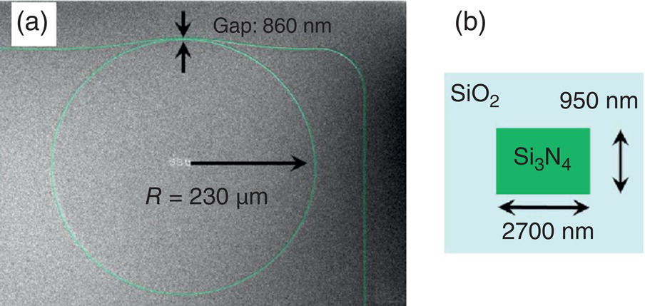
Figure 6.29 (a) Scanning electron microscope image of a 2.6‐μm‐pumped Si3N4 ring resonator. (b) Schematic of the resonator cross section.
Source: adapted from figure 2 of [140], with permission of OSA, The Optical Society.
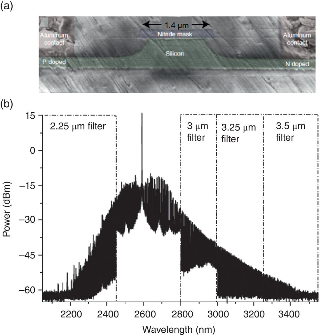
Figure 6.30 (a) Cross‐sectional SEM image of a silicon waveguide. (b) Spectrum of a frequency comb from a silicon microresonator pumped at 2.59 μm. A series of optical bandpass filters were used to measure the spectrum.
Source: adapted from figures 1 and 3 from [110], with permission of Springer Nature.
Wang et al. produced a 2.35–2.55 μm Kerr frequency comb using an ultrahigh Q magnesium fluoride (MgF2) crystalline resonator pumped by the output of a CW OPO at 2.45 μm with 600 mW of average power. The comb had a mode spacing of 107 GHz and had low phase noise [112].
Lecaplain et al. reported a mid‐IR Kerr comb based on a high‐Q crystalline MgF2 resonator that was pumped by a CW quantum cascade laser (QCL) at 4.4 μm [113]. The light from the QCL was evanescently coupled to a MgF2 resonator via a chalcogenide tapered fiber. For a pump power of 80 mW the generated mid‐IR combs spanned from 4.1 to 4.7 μm with a mode spacing of 14.3 GHz, comprising more than 700 comb lines.
Similarly, Savchenkov et al. demonstrated mid‐IR Kerr combs in high‐finesse (Q = 2 × 10⁸) CaF2 and MgF2 whispering‐gallery mode resonators pumped with a CW distributed‐feedback QCL at 4.5 μm. Kerr combs were generated starting from the coupled pump power of only 2 mW. The largest Kerr comb stretch, from 3.7 to 5.5 μm, was attained in the MgF2 microresonator at a coupled pump power of 55 mW [114]. However, the comb line spacing in this work was large, 2.1 THz – a multiple of the free spectral range of the resonator (19.3 GHz), and further study of coherence properties is required.
6.2.7 Combs from Quantum Cascade Lasers
Quantum cascade lasers (QCLs) are direct and compact mid‐IR sources that use electrical injection to provide optical gain (see Chapter 4). Hugi et al. reported the first mid‐IR frequency comb generator based on a QCL [115]. The authors demonstrated that under certain drive currents, the modes of a CW, free‐running, broadband QCL could be passively phase‐locked. Measurements of coherence properties [115] indicated that the phase relations between the comb lines are similar to that of a frequency‐modulated (FM) laser, and the locking mechanism responsible for the formation of the frequency comb is four‐wave mixing. This mechanism is facilitated by strong third‐order optical nonlinearity and a low GVD of a broadband QCL structure. The comb spanned from 6.8 to 7.3 μm (−20 dB level) with the mode spacing of 7.5 GHz. The inter‐mode beat linewidth was measured to be less than 250 kHz [115]. In the subsequent work, the same team has demonstrated that the equidistance of the comb lines is preserved to a fractional accuracy of 7.5 × 10⁻¹⁶ [141].
Most recently, Lu et al. demonstrated a frequency comb source at λ ≈ 8 μm, based on a dispersion‐compensated QCL structure, with a high‐power output of 880 mW at room temperature [116]. The spectral coverage of the QCL comb device was 110 cm−1 with the mode spacing 11.2 GHz, which corresponds to ~290 lasing modes. The comb device exhibited a narrow intermodal beatnote linewidth of 50.5 Hz and a maximum wall‐plug efficiency of 6.5%. This efficiency was a factor of 6 increase, as compared to previous demonstrations. Furthermore, narrow intermodal beatnote linewidths (<305 Hz) were observed over a wide range of pump currents (25% of the total range).
6.2.8 Combs from Interband Cascade Lasers
Interband cascade lasers (ICLs) – another class of electrically pumped semiconductor lasers (see Chapter 4) – operate at 3–6 μm and are ideal for many low‐power spectroscopic applications since they consume much less drive power than QCLs. This is especially advantageous in battery‐powered sensing systems, or for applications that require small size and weight. ICLs can be best operated in the important 3–4 μm band, a band where a large fraction of the absorption features associated with C─H bonds are clustered, and where QCL performance degrades.
Bagheri et al. demonstrated an electrically driven frequency comb source based on an ICL that spans more than 1 THz (35 cm−1, 52 nm) of bandwidth near λ ≈ 3.6 μm. This was achieved by passively mode‐locking an ICL, where gain and saturable absorber sections were monolithically integrated on the same chip [117]. Figure 6.31a shows the schematic of a laser cavity with gain and saturable absorber sections, where the saturable absorber imposes pulsed operation by providing an intensity‐dependent loss mechanism. Also shown (Figure 6.31c and d) is an FTIR spectrum of the mode‐locked ICL operating at I = 325 mA current and T = 15 °C temperature, showing 35 cm−1 bandwidth and >120 modes spaced by 9.7 GHz. The intensity autocorrelation measurements performed by the authors have shown that the mode‐locked ICL emitted pulses of ≈750 fs width.
The main results for frequency comb laser sources are presented in Table 6.2.
6.3 Summary
Producing “white light” in the mid‐IR via SC generation can be achieved in various media, with a continuous wavelength span of up to several octaves and a longwave limit beyond 10 μm. With HNLFs and waveguides, SC generation can be accomplished with modest pump peak powers, which opens up new possibilities for creating a compact light source for the needs of mid‐IR spectroscopy and sensing. Phase‐locked frequency combs in the mid‐IR – a time‐coherent version of the SC – offer immense potential for high‐precision, high‐resolution, and high‐sensitivity molecular spectroscopy. The most promising techniques for producing combs include those based on direct comb generation with mode‐locked fiber‐ and solid‐state lasers, parametric devices (using χ(2) crystals), and hyper‐parametric devices (based on χ(3) in fibers, waveguides, and microresonators). The newly developed electrically pumped QCL and ICL combs show potential for efficient and compact comb sources.
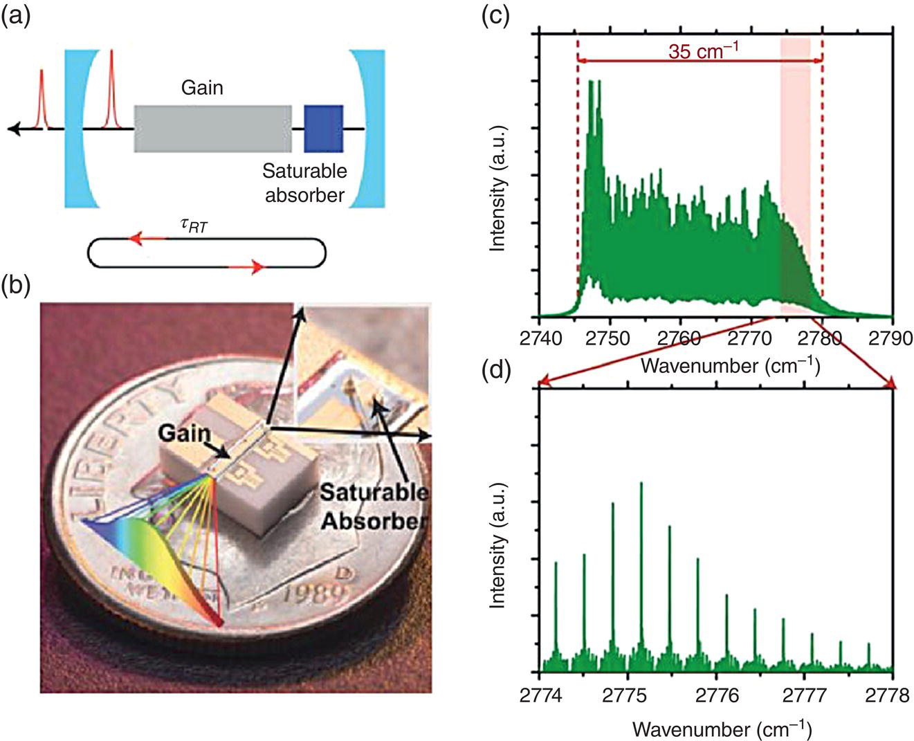
Figure 6.31 Frequency comb source based on passively mode‐locked interband cascade laser (ICL). (a) Schematic of the laser cavity with gain and saturable absorber sections, where the saturable absorber imposes pulsed operation via intensity‐dependent loss. (b) An ICL mode‐locked laser with gain (front) and saturable absorber (back) sections. (c) FTIR spectrum of the ICL operating at I = 325 mA and T = 15 °C, with 35 cm−1 bandwidth and >120 modes. (d) A portion of the spectrum measured by a high‐resolution (100 MHz) FTIR.
Source: adapted from figures 1 and 2 of [117], with permission of Springer Nature.
References
- 1 Alfano, R.R. and Shapiro, S.L. (1970). Emission in the region 4000 to 7000 Å via four‐photon coupling in glass. Phys. Rev. Lett. 24: 584.
- 2 Corkum, P.B., Ho, P.P., Alfano, R.R., and Manassah, J.T. (1985). Generation of infrared supercontinuum covering 3–14 μm in dielectrics and semiconductors. Opt. Lett. 10: 624.
- 3 Agrawal, G.P. (2013). Nonlinear Fiber Optics, 5e. Oxford: Academic Press.
- 4 Dudley, J.M., Genty, G., and Coen, S. (2006). Supercontinuum generation in photonic crystal fiber. Rev. Mod. Phys. 78: 1135.
- 5 Dudley, J.M. and Taylor, J.R. (eds.) (2010). Supercontinuum Generation in Optical Fibers. Cambridge: Cambridge University Press.
- 6 Islam, M.N., Sucha, G., Bar‐Joseph, I., Wegener, M., Gordon, J.P., and Chemla, D.S. (1989). Femtosecond distributed soliton spectrum in fibers. J. Opt. Soc. Am. B 6: 1149.
- 7 R. Paschotta, Encyclopedia of Laser Physics and Technology, http://www.rp‐photonics.com, accessed 21 November 2018.
- 8 Rothenberg, J.E. and Grischkowsky, D. (1989). Observation of the formation of an optical intensity shock and wave breaking in the nonlinear propagation of pulses in optical fibers. Phys. Rev. Lett. 62: 531.
- 9 Omenetto, F.G., Wolchover, N.A., Wehner, M.R., Ross, M., Efimov, A., Taylor, A.J., Kumar, V.V.R.K., George, A.K., Knight, J.C., Joly, N.Y., and Russell, P.St.J. (2006). Spectrally smooth supercontinuum from 350 nm to 3 μm in sub‐centimeter lengths of soft‐glass photonic crystal fibers. Opt. Express 14: 4928.
- 10 Domachuk, P., Wolchover, N.A., Cronin‐Golomb, M., Wang, A., George, A.K., Cordeiro, C.M.B., Knight, J.C., and Omenetto, F.G. (2008). Over 4000 nm bandwidth of mid‐IR supercontinuum generation in sub‐centimeter segments of highly nonlinear tellurite PCFs. Opt. Express 16: 7161.
- 11 Hagen, C.L., Walewski, J.W., and Sanders, S.T. (2006). Generation of a continuum extending to the midinfrared by pumping ZBLAN fiber with an ultrafast 1550‐nm source. IEEE Photon. Technol. Lett. 18: 91.
- 12 Xia, C., Kumar, M., Kulkarni, O.P., Islam, M.N., Terry, F.L. Jr., Freeman, M.J., Poulain, M., and Mazé, G. (2006). Mid‐infrared supercontinuum generation to 4.5 μm in ZBLAN fluoride fibers by nanosecond diode pumping. Opt. Lett. 31: 2553.
- 13 Xia, C., Kumar, M., Cheng, M.‐Y., Hegde, R.S., Islam, M.N., Galvanauskas, A., Winful, H.G., Terry Jr, F.L., Freeman, M.J., Poulain, M., and Mazé, G. (2007). Power scalable mid‐infrared supercontinuum generation in ZBLAN fluoride fibers with up to 1.3 watts time‐averaged power. Opt. Express 15: 865.
- 14 Xia, C., Xu, Z., Islam, M.N., Terry, F.L. Jr., Freeman, M.J., Zakel, A., and Mauricio, J. (2009). 10.5 W time‐averaged power mid‐IR supercontinuum generation extending beyond 4 μm with direct pulse pattern modulation. IEEE J. Sel. Topics Quantum Electron. 15: 422.
- 15 Liu, K., Liu, J., Shi, H., Tan, F., and Wang, P. (2014). High power mid‐infrared supercontinuum generation in a single‐mode ZBLAN fiber with up to 21.8 W average output power. Opt. Express 22: 24384.
- 16 Yang, W., Zhang, B., Xue, G., Yin, K., and Hou, J. (2014). Thirteen watt all‐fiber mid‐infrared supercontinuum generation in a single mode ZBLAN fiber pumped by a 2 μm MOPA system. Opt. Lett. 39: 1849.
- 17 Qin, G., Yan, X., Kito, C., Liao, M., Chaudhari, C., Suzuki, T., and Ohishia, Y. (2009). Ultrabroadband supercontinuum generation from ultraviolet to 6.28 μm in a fluoride fiber. Appl. Phys. Lett. 96: 161103.
- 18 Eggleton, B.J., Luther‐Davies, B., and Richardson, K. (2011). Chalcogenide photonics. Nat. Photonics 5: 141.
- 19 Snopatin, G.E., Shiryaev, V.S., Plotnichenko, V.G., Dianov, E.M., and Churbanov, M.F. (2009). High‐purity chalcogenide glasses for fiber optics. Inorg. Mater. 45: 14391460.
- 20 Shiryaev, V.S. and Churbanov, M.F. (2013). Trends and prospects for development of chalcogenide fibers for mid‐infrared transmission. J. Non‐Cryst. Solids 377: 225.
- 21 Hu, J., Menyuk, C.R., Shaw, L.B., Sanghera, J.S., and Aggarwal, I.D. (2010). Computational study of 3–5 μm source created by using supercontinuum generation in As2S3 chalcogenide fibers with a pump at 2 μm. Opt. Lett. 35: 2907.
- 22 Shabahang, S., Tao, G., Marquez, M.P., Hu, H., Ensley, T.R., Delfyett, P.J., and Abouraddy, A.F. (2014). Nonlinear characterization of robust multimaterial chalcogenide nanotapers for infrared supercontinuum generation. J. Opt. Soc. Am. B 31: 450.
- 23 El‐Amraoui, M., Gadret, G., Jules, J.C., Fatome, J., Fortier, C., Désévédavy, F., Skripatchev, I., Messaddeq, Y., Troles, J., Brilland, L., Gao, W., Suzuki, T., Ohishi, Y., and Smektala, F. (2010). Microstructured chalcogenide optical fibers from As2S3 glass: towards new IR broadband sources. Opt. Express 18: 26655.
- 24 Yeom, D., Mägi, E.C., Lamont, M.R.E., Roelens, M.A.F., Fu, L., and Eggleton, B.J. (2008). Low‐threshold supercontinuum generation in highly nonlinear chalcogenide nanowires. Opt. Lett. 33: 660.
- 25 Mägi, E.C., Fu, L.B., Nguyen, H.C., Lamont, M.R., Yeom, D.I., and Eggleton, B.J. (2007). Enhanced Kerr nonlinearity in sub‐wavelength diameter As2Se3 chalcogenide fiber tapers. Opt. Express 15: 10324.
- 26 Hudson, D.D., Dekker, S.A., Mägi, E.C., Judge, A.C., Jackson, S.D., Li, E., Sanghera, J.S., Shaw, L.B., Aggarwal, I.D., and Eggleton, B.J. (2011). Octave spanning supercontinuum in an As2S3 taper using ultralow pump pulse energy. Opt. Lett. 36: 1122.
- 27 Shabahang, S., Marquez, M.P., Tao, G., Piracha, M.U., Nguyen, D., Delfyett, P.J., and Abouraddy, A.F. (2012). Octave‐spanning infrared supercontinuum generation in robust chalcogenide nanotapers using picosecond pulses. Opt. Lett. 37: 4639.
- 28 Sanghera, J.S., Shaw, L.B., and Aggarwal, I.D. (2009). Chalcogenide glass‐fiber‐based mid‐IR sources and applications. IEEE J. Sel. Topics Quantum Electron. 15: 114.
- 29 Mouawad, O., Picot‐Clemente, J., Amrani, F., Strutynski, C., Fatome, J., Kibler, B., Dsvdavy, F., Gadret, G., Jules, J.‐C., Deng, D., Ohishi, Y., and Smektala, F. (2014). Multioctave midinfrared supercontinuum generation in suspended‐core chalcogenide fibers. Opt. Lett. 39: 2684.
- 30 Marandi, A., Rudy, C.W., Plotnichenko, V.G., Dianov, E.M., Vodopyanov, K.L., and Byer, R.L. (2012). Mid‐infrared supercontinuum generation in tapered chalcogenide fiber for producing octave‐spanning frequency comb around 3 μm. Opt. Express 20: 24218.
- 31 Rudy, C.W., Marandi, A., Vodopyanov, K.L., and Byer, R.L. (2013). Octave‐spanning supercontinuum generation in in situ tapered As2S3 fiber pumped by a thulium‐doped fiber laser. Opt. Lett. 38: 2865.
- 32 Al‐Kadry, A., Amraoui, M.E., Messaddeq, Y., and Rochette, M. (2014). Two octaves mid‐infrared supercontinuum generation in As2Se3 microwires. Opt. Express 22: 31131.
- 33 Yu, Y., Zhang, B., Gai, X., Zhai, C., Qi, S., Guo, W., Yang, Z., Wang, R., Choi, D.‐Y., Madden, S., and Luther‐Davies, B. (2015). 1.8‐10 μm mid‐infrared supercontinuum generated in a step‐index chalcogenide fiber using low peak pump power. Opt. Lett. 40: 1081.
- 34 Møller, U., Yu, Y., Kubat, I., Petersen, C.R., Gai, X., Brilland, L., Méchin, D., Caillaud, C., Troles, J., Luther‐Davies, B., and Bang, O. (2015). Multi‐milliwatt mid‐infrared supercontinuum generation in a suspended core chalcogenide fiber. Opt. Express 23: 3282.
- 35 Hudson, D.D., Baudisch, M., Werdehausen, D., Eggleton, B.J., and Biegert, J. (2014). 1.9 octave supercontinuum generation in a As2S3 step‐index fiber driven by mid‐IR OPCPA. Opt. Lett. 39: 5752.
- 36 Robichaud, L.‐R., Fortin, V., Gauthier, J.‐C., Châtigny, S., Couillard, J.‐F., Delarosbil, J.‐L., Vallée, R., and Bernier, M. (2016). Compact 3‐8 μm supercontinuum generation in a low‐loss As2Se3 step‐index fiber. Opt. Lett. 41: 4605.
- 37 Petersen, C.R., Møller, U., Kubat, I., Zhou, B., Dupont, S., Ramsay, J., Benson, T., Sujecki, S., Abdel‐Moneim, N., Tang, Z., Furniss, D., Seddon, A., and Bang, O. (2014). Mid‐infrared supercontinuum covering the 1.4–13.3 μm molecular fingerprint region using ultra‐high NA chalcogenide step‐index fibre. Nat. Photonics 8: 830.
- 38 Hudson, D.D., Antipov, S., Li, L., Alamgir, I., Hu, T., El Amraoui, M., Messaddeq, Y., Rochette, M., Jackson, S.D., and Fuerbach, A. (2017). Toward all‐fiber supercontinuum spanning the mid‐infrared. Optica 4: 1163.
- 39 Cheng, T., Nagasaka, K., Tuan, T.H., Xue, X., Matsumoto, M., Tezuka, H., Suzuki, T., and Ohishi, Y. (2016). Mid‐infrared supercontinuum generation spanning 2.0 to 15.1 μm in a chalcogenide step‐index fiber. Opt. Lett. 41: 2117.
- 40 Zhao, Z., Wu, B., Wang, X., Pan, Z., Liu, Z., Zhang, P., Shen, X., Nie, Q., Dai, S., and Wang, R. (2017). Mid‐infrared supercontinuum covering 2.0–16 μm in a low‐loss telluride single‐mode fiber. Laser Photonics Rev. 11: 1700005.
- 41 Lamont, M.R.E., Luther‐Davies, B., Choi, D.‐Y., Madden, S., and Eggleton, B.J. (2008). Supercontinuum generation in dispersion engineered highly nonlinear (γ = 10 /W/m) As2S3 chalcogenide planar waveguide. Opt. Lett. 16: 14938.
- 42 Xie, S., Tolstik, N., Travers, J.C., Sorokin, E., Caillaud, C., Troles, J., Russell, St.P.J., and Sorokina, I.T. (2016). Coherent octave‐spanning mid‐infrared supercontinuum generated in As2S3‐silica double‐nanospike waveguide pumped by femtosecond Cr:ZnS laser. Opt. Express 24: 12406.
- 43 Yu, Y., Gai, X., Ma, P., Choi, D.Y., Yang, Z.Y., Wang, R.P., Debbarma, S., Madden, S.J., and Luther‐Davies, B. (2014). A broadband, quasi‐continuous, mid‐infrared supercontinuum generated in a chalcogenide glass waveguide. Laser Photonics Rev. 8: 792.
- 44 Lau, R.K.W., Lamont, M.R.E., Griffith, A.G., Okawachi, Y., Lipson, M., and Gaeta, A.L. (2014). Octave‐spanning mid‐infrared supercontinuum generation in silicon nanowaveguides. Opt. Lett. 39: 4518.
- 45 Singh, N., Hudson, D.D., Yu, Y., Grillet, C., Jackson, S.D., Casas‐Bedoya, A., Read, A., Atanackovic, P., Duvall, S.G., Palomba, S., Luther‐Davies, B., Madden, S., Moss, D.J., and Eggleton, B.J. (2015). Midinfrared supercontinuum generation from 2 to 6 μm in a silicon nanowire. Optica 2: 797.
- 46 Phillips, C.R., Langrock, C., Pelc, J.S., Fejer, M.M., Jiang, J., Fermann, M.E., and Hartl, I. (2011). Supercontinuum generation in quasi‐phase‐matched LiNbO3 waveguide pumped by a Tm‐doped fiber laser system. Opt. Lett. 36: 3912.
- 47 Silva, F., Austin, D.R., Thai, A., Baudisch, M., Hemmer, M., Faccio, D., Couairon, A., and Biegert, J. (2012). Multi‐octave supercontinuum generation from mid‐infrared filamentation in a bulk crystal. Nat. Commun. 3: 807.
- 48 Belal, M., Xu, L., Horak, P., Shen, L., Feng, X., Ettabib, M., Richardson, D.J., Petropoulos, P., and Price, J.H.V. (2015). Mid‐infrared supercontinuum generation in suspended core tellurite microstructured optical fibers. Opt. Lett. 40: 2237.
- 49 Yu, Y., Gai, X., Wang, T., Ma, P., Wang, R., Yang, Z., Choi, D.‐Y., Madden, S., and Luther‐Davies, B. (2013). Mid‐infrared supercontinuum generation in chalcogenides. Opt. Mater. Express 3: 1075.
- 50 Liao, M., Gao, W., Cheng, T., Xue, X., Duan, Z., Deng, D., Kawashima, H., Suzuki, T., and Ohishi, Y. (2013). Five‐octave‐spanning supercontinuum generation in fluoride glass. Appl. Phys. Express 6: 032503.
- 51 Liang, H., Krogen, P., Grynko, R., Novak, O., Chang, C.‐L., Stein, G.J., Weerawarne, D., Shim, B., Kärtner, F.X., and Hong, K.‐H. (2015). Three‐octave spanning supercontinuum generation and sub‐two‐cycle self‐compression of mid‐infrared filaments in dielectrics. Opt. Lett. 40: 1069.
- 52 Suminas, R., Tamošauskas, G., Valiulis, G., Jukna, V., Couairon, A., and Dubietis, A. (2017). Multi‐octave spanning nonlinear interactions induced by femtosecond filamentation in polycrystalline ZnSe. Appl. Phys. Lett. 110: 241106.
- 53 Mouawad, O., Béjot, P., Billard, F. Mathey, P., Kibler, B., Désévédavy, F., Gadret, G., Jules, J.‐C., Faucher, O., and Smektala, F. (2016). Filament‐induced visible‐to‐mid‐IR supercontinuum in a ZnSe crystal: towards multioctave supercontinuum absorption spectroscopy. Opt. Mater. 60: 355.
- 54 Vasilyev, S., Moskalev, I., Mirov, M., Smolski, V., Mirov, S., and Gapontsev, V. (2017). Ultrafast middle‐IR lasers and amplifiers based on polycrystalline Cr:ZnS and Cr:ZnSe. Opt. Mater. Express 7: 2636.
- 55 Ashihara, S. and Kawahara, Y. (2009). Spectral broadening of mid‐infrared femtosecond pulses in GaAs. Opt. Lett. 34: 3839.
- 56 Pigeon, J.J., Tochitsky, S.Ya., Gong, C., and Joshi, C. (2014). Supercontinuum generation from 2 to 20 μm in GaAs pumped by picosecond CO2 laser pulses. Opt. Lett. 39: 3246.
- 57 Kartashov, D., Ališauskas, S., Pugžlys, A., Voronin, A., Zheltikov, A., Petrarca, M., Béjot, P., Kasparian, J., Wolf, J.‐P., and Baltuška, A. (2012). White light generation over three octaves by femtosecond filament at 3.9 μm in argon. Opt. Lett. 37: 3456.
- 58 Hänsch, T.W. (2006). Nobel lecture: Passion for precision. Rev. Mod. Phys. 78: 1297.
- 59 Cundiff, S.T. and Ye, J. (2003). Colloquium: Femtosecond optical frequency combs. Rev. Mod. Phys. 75: 325.
- 60 Popmintchev, T., Chen, M.‐C., Arpin, P., Murnane, M.M., and Kapteyn, H.C. (2010). The attosecond nonlinear optics of bright coherent X‐ray generation. Nat. Photonics 4: 822.
- 61 Corkum, P.B. and Krausz, F. (2007). Attosecond science. Nat. Phys. 3: 381.
- 62 Sears, C.M.S., Colby, E., England, R.J., Ischebeck, R., McGuinness, C., Nelson, J., Noble, R., Siemann, R.H., Spencer, J., Walz, D., Plettner, T., and Byer, R.L. (2008). Phase stable net acceleration of electrons from a two‐stage optical accelerator. Phys. Rev. Spec. Topics Accelerators Beams 11: 101301.
- 63 Coddington, I., Newbury, N., and Swann, W. (2016). Dual‐comb spectroscopy. Optica 3: 414.
- 64 Muraviev, A.V., Smolski, V.O., Loparo, Z.E., and Vodopyanov, K.L. (2018). Massively parallel sensing of trace molecules and their isotopologues with broadband subharmonic mid‐infrared frequency combs. Nat. Photonics 12: 209.
- 65 Timmers, H., Kowligy, A., Lind, A., Cruz, F.C., Nader, N., Silfies, M., Ycas, G., Allison, T.K., Schunemann, P.G., Papp, S.B., and Diddams, S.A. (2018). Molecular fingerprinting with bright, broadband infrared frequency combs. Optica 5: 727.
- 66 Dudley, J.M. and Coen, S. (2002). Coherence properties of supercontinuum spectra generated in photonic crystals and tapered optical fibers. Opt. Lett. 27: 1180.
- 67 Bellini, M. and Hänsch, T.W. (2000). Phase‐locked white‐light continuum pulses: toward a universal optical frequency‐comb synthesizer. Opt. Lett. 25: 1049.
- 68 Schliesser, A., Picqué, N., and Hänsch, T.W. (2012). Mid‐infrared frequency combs. Nat. Photonics 6: 440.
- 69 Lee, C.‐C., Mohr, C., Bethge, J., Suzuki, S., Fermann, M.E., Hartl, I., and Schibli, T.R. (2012). Frequency comb stabilization with bandwidth beyond the limit of gain lifetime by an intracavity graphene electro‐optic modulator. Opt. Lett. 37: 3084.
- 70 Bethge, J., Jiang, J., Mohr, C., Fermann, M., and Hartl, I. (2012). Optically referenced Tm‐fiber‐laser frequency comb, Technical Digest. In: Advanced Solid‐State Photonics. Washington, DC: Optical Society of America, Paper AT5A.3.
- 71 Lee, K.F., Jiang, J., Mohr, C., Bethge, J., Fermann, M.E., Leindecker, N., Vodopyanov, K.L., Schunemann, P.G., and Hartl, I. (2013). Carrier envelope offset frequency of a doubly resonant, nondegenerate, mid‐infrared GaAs optical parametric oscillator. Opt. Lett. 38: 1191.
- 72 Lee, K.F., Mohr, C., Jiang, J., Schunemann, P.G., Vodopyanov, K.L., and Fermann, M.E. (2015). Midinfrared frequency comb from self‐stable degenerate GaAs optical parametric oscillator. Opt. Express 23: 26596.
- 73 Mirov, S., Fedorov, V., Martyshkin, D., Moskalev, I., Mirov, M., and Vasilyev, S. (2015). Progress in mid‐IR lasers based on Cr and Fe doped II‐VI Chalcogenides. IEEE J. Sel. Topics Quantum Electron. 21: 1601719.
- 74 Vasilyev, S., Moskalev, I., Smolski, V., Peppers, J., Mirov, M., Fedorov, V., Martyshkin, D., Mirov, S., and Gapontsev, V. (2019). Octave‐spanning Cr:ZnS femtosecond laser with intrinsic nonlinear interferometry. Optica 6: 126.
- 75 Vasilyev, S., Smolski,V., Peppers, J., Moskalev, I., Mirov, M., Barnakov, Y., Mirov, S., and Gapontsev, V. (2019). Middle‐IR frequency comb based on Cr:ZnS laser. Opt. Express. 27: 35079.
- 76 Duval, S., Bernier, M., Fortin, V., Genest, J., Piché, M., and Vallée, R. (2015). Femtosecond fiber lasers reach the midinfrared. Optica 2: 623.
- 77 Washburn, B.R., Diddams, S.A., Newbury, N.R., Nicholson, J.W., Yan, M.F., and Jørgensen, C.G. (2004). Phase‐locked, erbium‐fiber‐laser‐based frequency comb in the near infrared. Opt. Lett. 29: 250.
- 78 Nicholson, J.W., Yan, M.F., Wisk, P., Fleming, J., DiMarcello, F., Monberg, E., Yablon, A., Jørgensen, C., and Veng, T. (2003). All‐fiber, octave‐spanning supercontinuum. Opt. Lett. 28: 643.
- 79 Granzow, N., Schmidt, M.A., Chang, W., Wang, L., Coulombier, Q., Troles, J., Toupin, P., Hartl, I., Lee, K.F., Fermann, M.E., Wondraczek, L., and Russell, P.St.J. (2013). Mid‐infrared supercontinuum generation in As2S3‐silica nano‐spike step‐index waveguide. Opt. Express 21: 10969.
- 80 Lee, K.F., Granzow, N., Schmidt, M.A., Chang, W., Wang, L., Coulombier, Q., Troles, J., Leindecker, N., Vodopyanov, K.L., Schunemann, P.G., Fermann, M.E., Russell, P.St.J., and Hartl, I. (2014). Midinfrared frequency combs from coherent supercontinuum in chalcogenide and optical parametric oscillation. Opt. Lett. 39: 2056.
- 81 Kuyken, B., Ideguchi, T., Holzner, S., Yan, M., Hänsch, T.W., Van Campenhout, J., Verheyen, P., Coen, S., Leo, F., Baets, R., Roelkens, G., and Picqué, N. (2015). An octave‐spanning mid‐infrared frequency comb generated in a silicon nanophotonic wire waveguide. Nat. Commun. 6: 6310.
- 82 Maddaloni, P., Malara, P., Gagliardi, G., and De Natale, P. (2006). Mid‐infrared fibre‐based optical comb. New J. Phys. 8: 262.
- 83 Galli, I., Cappelli, F., Cancio, P., Giusfredi, G., Mazzotti, D., Bartalini, S., and De Natale, P. (2013). High‐coherence mid‐infrared frequency comb. Opt. Express 21: 28877.
- 84 Erny, C., Moutzouris, K., Biegert, J., Kühlke, D., Adler, F., Leitenstorfer, A., and Keller, U. (2007). Mid‐infrared difference‐frequency generation of ultrashort pulses tunable between 3.2 and 4.8 μm from a compact fiber source. Opt. Lett. 32: 1138.
- 85 Neely, T.W., Johnson, T.A., and Diddams, S.A. (2011). Mid‐infrared optical combs from a compact amplified Er‐doped fiber oscillator. Opt. Lett. 36: 4020.
- 86 Zhu, F., Hundertmark, H., Kolomenskii, A.A., Strohaber, J., Holzwarth, R., and Schuessler, H.A. (2013). High‐power midinfrared frequency comb source based on a femtosecond Er:fiber oscillator. Opt. Lett. 38: 2360.
- 87 Meek, S.A., Poisson, A., Guelachvili, G., Hänsch, T.W., and Picqué, N. (2014). Fourier transform spectroscopy around 3 μm with a broad difference frequency comb. Appl. Phys. B 114: 573.
- 88 Cruz, F.C., Maser, D.L., Johnson, T., Ycas, G., Klose, A., Giorgetta, F.R., Coddington, I., and Diddams, S.A. (2015). Mid‐infrared optical frequency combs based on difference frequency generation for molecular spectroscopy. Opt. Express 23: 26814.
- 89 Maser, D.L., Ycas, G., Depetri, W.I., Cruz, F.C., and Diddams, S.A. (2017). Coherent frequency combs for spectroscopy across the 3–5 μm region. Appl. Phys. B 123: 142.
- 90 Lee, K.F., Hensley, C.J., Schunemann, P.G., and Fermann, M.E. (2017). Midinfrared frequency comb by difference frequency of erbium and thulium fiber lasers in orientation‐patterned gallium phosphide. Opt. Express 25: 17411.
- 91 Gambetta, A., Ramponi, R., and Marangoni, M. (2008). Mid‐infrared optical combs from a compact amplified Er‐doped fiber oscillator. Opt. Lett. 33: 2671.
- 92 Gambetta, A., Coluccelli, N., Cassinerio, M., Gatti, D., Laporta, P., Galzerano, G., and Marangoni, M. (2013). Milliwatt‐level frequency combs in the 8–14 μm range via difference frequency generation from an Er:fiber oscillator. Opt. Lett. 38: 1155.
- 93 Ruehl, A., Gambetta, A., Hartl, I., Fermann, M.E., Eikema, K.S.E., and Marangoni, M. (2012). Widely‐tunable mid‐infrared frequency comb source based on difference frequency generation. Opt. Lett. 37: 2232.
- 94 Keilmann, F. and Amarie, S. (2012). Mid‐infrared frequency comb spanning an octave based on an Er fiber laser and difference‐frequency generation. J. Infrared Milli. Terahz Waves 33: 479.
- 95 Adler, F., Cossel, K.C., Thorpe, M.J., Hartl, I., Fermann, M.E., and Ye, J. (2009). Phase‐stabilized, 1.5 W frequency comb at 2.8–4.8 μm. Opt. Lett. 34: 1330.
- 96 McCracken, R.A., Sun, J., Leburn, C.G., and Reid, D.T. (2012). Broadband phase coherence between an ultrafast laser and an OPO using lock‐to‐zero CEO stabilization. Opt. Express 20: 16269.
- 97 Zhang, Z., Sun, J., Gardiner, T., and Reid, D.T. (2011). Broadband conversion in an Yb:KYW‐pumped ultrafast optical parametric oscillator with a long nonlinear crystal. Opt. Express 19: 17127.
- 98 Gu, C., Hu, M., Zhang, L., Fan, J., Song, Y., Wang, C., and Reid, D.T. (2013). High average power, widely tunable femtosecond laser source from red to mid‐infrared based on an Yb‐fiber‐laser‐pumped optical parametric oscillator. Opt. Lett. 38: 1820.
- 99 Jin, Y., Cristescu, S.M., Harren, F.J.M., and Mandon, J. (2014). Two‐crystal mid‐infrared optical parametric oscillator for absorption and dispersion dual‐comb spectroscopy. Opt. Lett. 39: 3270.
- 100 Jin, Y., Cristescu, S.M., Harren, F.J.M., and Mandon, J. (2015). Femtosecond optical parametric oscillators toward real‐time dual‐comb spectroscopy. Appl. Phys. B 119: 65.
- 101 Coluccelli, N., Fonnum, H., Haakestad, M., Gambetta, A., Gatti, D., Marangoni, M., Laporta, P., and Galzerano, G. (2012). 250‐MHz synchronously pumped optical parametric oscillator at 2.25–2.6 μm and 4.1–4.9 μm. Opt. Express 20: 22042.
- 102 Leindecker, N., Marandi, A., Byer, R.L., and Vodopyanov, K.L. (2011). Broadband degenerate OPO for mid‐infrared frequency comb generation. Opt. Express 19: 6296.
- 103 Ru, Q., Loparo, Z.E., Zhang, X., Crystal, S., Vasu, S., Schunemann, P.G., and Vodopyanov, K.L. (2017). Self‐referenced octave‐wide subharmonic GaP optical parametric oscillator centered at 3 μm and pumped by an Er‐fiber laser. Opt. Lett. 42: 4756.
- 104 Smolski, V.O., Yang, H., Gorelov, S.D., Schunemann, P.G., and Vodopyanov, K.L. (2016). Coherence properties of a 2.6–7.5 μm frequency comb produced as a subharmonic of a Tm‐fiber laser. Opt. Lett. 41: 1388.
- 105 Ru, Q., Zhong, K., Lee, N.P., Loparo, Z.E., Schunemann, P.G., Vasilyev, S., Mirov, S.B., and Vodopyanov, K.L. (2017). Instantaneous spectral span of 2.85–8.40 μm achieved in a Cr:ZnS laser pumped subharmonic GaAs OPO, Technical Digest (Online). In: Conference on Lasers and Electro‐Optics. Washington, DC: Optical Society of America, Paper SM4M.3.
- 106 Smolski, V., Vasilyev, S., Moskalev, I., Mirov, M., Ru, Q., Muraviev, A., Schunemann, P., Mirov, S., Gapontsev, V., and Vodopyanov, K. (2018). Half‐watt average power femtosecond source spanning 3–8 μm based on subharmonic generation in GaAs. App. Phys. B 124: 101.
- 107 Ru, Q., Schunemann, P.G., Vasilyev, S., Mirov, S.B., and Vodopyanov, K.L. (2019). A 2.35‐μm pumped subharmonic OPO reaches the spectral width of two octaves in the mid‐IR, Technical Digest (Online). In: Conference on Lasers and Electro‐Optics. Washington, DC: Optical Society of America, Paper SF1H.1.
- 108 Del'Haye, P., Herr, T., Gavartin, E., Gorodetsky, M.L., Holzwarth, R., and Kippenberg, T.J. (2011). Octave spanning tunable frequency comb from a microresonator. Phys. Rev. Lett. 107: 063901.
- 109 Okawachi, Y., Saha, K., Levy, J.S., Wen, Y.H., Lipson, M., and Gaeta, A.L. (2011). Octave‐spanning frequency comb generation in a silicon nitride chip. Opt. Lett. 36: 3398.
- 110 Griffith, A.G., Lau, R.K.W., Cardenas, J., Okawachi, Y., Mohanty, A., Fain, R., Lee, Y.H.D., Yu, M., Phare, C.T., Poitras, C.B., Gaeta, A.L., and Lipson, M. (2015). Silicon‐chip mid‐infrared frequency comb generation. Nat. Commun. 6: 6299.
- 111 Griffith, A.G., Yu, M., Okawachi, Y., Cardenas, J., Mohanty, A., Gaeta, A.L., and Lipson, M. (2016). Coherent mid‐infrared frequency combs in silicon‐microresonators in the presence of Raman effects. Opt. Express 24: 13044.
- 112 Wang, C.Y., Herr, T., Del'Haye, P., Schliesser, A., Hofer, J., Holzwarth, R., Hänsch, T.W., Picqué, N., and Kippenberg, T.J. (2013). Mid‐infrared optical frequency combs at 2.5 μm based on crystalline microresonators. Nat. Commun. 4: 1345.
- 113 Lecaplain, C., Javerzac‐Galy, C., Lucas, E., Jost, J.D., and Kippenberg, T.J. (2015). Quantum cascade laser Kerr frequency comb. ArXiv:1506.00626
- 114 Savchenkov, A.A., Ilchenko, V.S., Di Teodoro, F., Belden, P.M., Lotshaw, W.T., Matsko, A.B., and Maleki, L. (2015). Generation of Kerr combs centered at 4.5 μm in crystalline microresonators pumped with quantum‐cascade lasers. Opt. Lett. 40: 3468.
- 115 Hugi, A., Villares, G., Blaser, S., Liu, H.C., and Faist, J. (2012). Midinfrared frequency comb based on a quantum cascade laser. Nature 492: 229.
- 116 Lu, Q., Wu, D., Slivken, S., and Razeghi, M. (2017). High efficiency quantum cascade laser frequency comb. Sci. Rep. 7: 43806.
- 117 Bagheri, M., Frez, C., Sterczewski, L.A., Gruidin, I., Fradet, M., Vurgaftman, I., Canedy, C.L., Bewley, W.W., Merritt, C.D., Kim, C.S., Kim, M., and Meyer, J.R. (2018). Passively mode‐locked interband cascade optical frequency combs. Sci. Rep. 8: 3322.
- 118 Sun, J.H., Gale, B.J.S., and Reid, D.T. (2007). Composite frequency comb spanning 0.4–2.4 μm from a phase controlled femtosecond Ti:sapphire laser and synchronously pumped optical parametric oscillator. Opt. Lett. 32: 1414.
- 119 Adler, F., Maslowski, P., Foltynowicz, A., Cossel, K.C., Briles, T.C., Hartl, I., and Ye, J. (2010). Mid‐infrared Fourier transform spectroscopy with a broadband frequency comb. Opt. Express 18: 21861.
- 120 Iwakuni, K., Porat, G., Bui, T.Q., Bjork, B.J., Schoun, S.B., Heckl, O.H., Fermann, M.E., and Ye, J. (2018). Phase‐stabilized 100 mW frequency comb near 10 μm. Appl. Phys. B 124: 128.
- 121 Kobayashi, Y., Torizuka, K., Marandi, A., Byer, R.L., McCracken, R.A., Zhang, Z., and Reid, D.T. (2015). Femtosecond optical parametric oscillator frequency combs. J. Opt. 17: 94010.
- 122 Wong, S.T., Vodopyanov, K.L., and Byer, R.L. (2010). Self‐phase‐locked divide‐by‐2 optical parametric oscillator as a broadband frequency comb source. J. Opt. Soc. Am. B 27: 876.
- 123 Vodopyanov, K.L., Wong, S.T., and Byer, R.L. (2013). Infrared frequency comb methods, arrangements and applications. U.S. patent 8,384,990 (26 February 2013).
- 124 Leindecker, N., Marandi, A., Byer, R.L., Vodopyanov, K.L., Jiang, J., Hartl, I., Fermann, M., and Schunemann, P.G. (2012). Octave‐spanning ultrafast OPO with 2.6–6.1 μm instantaneous bandwidth pumped by femtosecond Tm‐fiber laser. Opt. Express 20: 7047.
- 125 Vodopyanov, K.L., Sorokin, E., Sorokina, I.T., and Schunemann, P.G. (2011). Mid‐IR frequency comb source spanning 4.4–5.4 μm based on subharmonic GaAs OPO. Opt. Lett. 36: 2275.
- 126 Smolski, V.O., Vasilyev, S., Schunemann, P.G., Mirov, S.B., and Vodopyanov, K.L. (2015). Cr:ZnS laser‐pumped subharmonic GaAs optical parametric oscillator with the spectrum spanning 3.6–5.6 μm. Opt. Lett. 40: 2906.
- 127 Marandi, A., Leindecker, N., Pervak, V., Byer, R.L., and Vodopyanov, K.L. (2012). Coherence properties of a broadband femtosecond mid‐IR optical parametric oscillator operating at degeneracy. Opt. Express 20: 7255.
- 128 Wan, C., Li, P., Ruehl, A., and Hartl, I. (2018). Coherent frequency division with a degenerate synchronously pumped optical parametric oscillator. Opt. Lett. 43: 1059.
- 129 Del'Haye, P., Schliesser, A., Arcizet, O., Wilke, T., Holzwarth, R., and Kippenberg, T.J. (2007). Optical frequency comb generation from a monolithic microresonator. Nature 450: 1214.
- 130 Kippenberg, T.J., Holzwarth, R., and Diddams, S.A. (2011). Microresonator‐based optical frequency combs. Science 332: 555.
- 131 Kippenberg, T.J., Spillane, S.M., and Vahala, K.J. (2004). Kerr‐nonlinearity optical parametric oscillation in an ultrahigh‐Q toroid microcavity. Phys. Rev. Lett. 93: 083904.
- 132 Savchenkov, A.A., Matsko, A.B., Strekalov, D., Mohageg, M., Ilchenko, V.S., and Maleki, L. (2004). Low threshold optical oscillations in a whispering gallery mode CaF2 resonator. Phys. Rev. Lett. 93: 243905.
- 133 Ferrera, M., Razzari, L., Duchesne, D., Morandotti, R., Yang, Z., Liscidini, M., Sipe, J.E., Chu, S., Little, B.E., and Moss, D.J. (2008). Low‐power continuous‐wave nonlinear optics in doped silica glass integrated waveguide structures. Nat. Photonics 2: 737.
- 134 Savchenkov, A.A., Matsko, A.B., Ilchenko, V.S., Solomatine, I., Seidel, D., and Maleki, L. (2008). Tunable optical frequency comb with a crystalline whispering gallery mode resonator. Phys. Rev. Lett. 101: 093902.
- 135 Grudinin, I.S., Yu, N., and Maleki, L. (2009). Generation of optical frequency combs with a CaF2 resonator. Opt. Lett. 34: 878.
- 136 Levy, J.S., Gondarenko, A., Foster, M.A., Turner‐Foster, A.C., Gaeta, A.L., and Lipson, M. (2010). CMOS‐compatible multiple‐wavelength oscillator for on‐chip optical interconnects. Nat. Photonics 4: 37.
- 137 Jung, H., Xiong, C., Fong, K.Y., Zhang, X.F., and Tang, H.X. (2013). Optical frequency comb generation from aluminum nitride microring resonator. Opt. Lett. 38: 2810.
- 138 Hausmann, B.J.M., Bulu, I., Venkataraman, V., Deotare, P., and Lončar, M. (2014). Diamond nonlinear photonics. Nat. Photonics 8: 369.
- 139 Foster, M.A., Levy, J.S., Kuzucu, O., Saha, K., Lipson, M., and Gaeta, A.L. (2011). Silicon‐based monolithic optical frequency comb source. Opt. Express 19: 14233.
- 140 Luke, K., Okawachi, Y., Lamont, M.R.E., Gaeta, A.L., and Lipson, M. (2015). Broadband mid‐infrared frequency comb generation in a Si3N4 microresonator. Opt. Lett. 40: 4823.
- 141 Villares, G., Hugi, A., Blaser, S., and Faist, J. (2014). Dual‐comb spectroscopy based on quantum‐cascade‐laser frequency combs. Nat. Commun. 5: 5192.