
Chapter 2: Kubernetes Networking
When thousands of microservices are running in a Kubernetes cluster, you may be curious about how these microservices communicate with each other as well as with the internet. In this chapter, we will unveil all the communication paths in a Kubernetes cluster. We want you to not only know how the communication happens but to also look into the technical details with a security mindset: a regular communication channel can always be abused as part of the kill chain.
In this chapter, we will cover the following topics:
- Overview of the Kubernetes network model
- Communicating inside a pod
- Communicating between pods
- Introducing the Kubernetes service
- Introducing the CNI and CNI plugins
Overview of the Kubernetes network model
Applications running on a Kubernetes cluster are supposed to be accessible either internally from the cluster or externally, from outside the cluster. The implication from the network's perspective is there may be a Uniform Resource Identifier (URI) or Internet Protocol (IP) address associated with the application. Multiple applications can run on the same Kubernetes worker node, but how can they expose themselves without conflicting with each other? Let's take a look at this problem together, and then dive into the Kubernetes network model.
Port-sharing problems
Traditionally, if there are two different applications running on the same machine where the machine IP is public and the two applications are publicly accessible, then the two applications cannot listen on the same port in the machine. If they both try to listen on the same port in the same machine, one application will not launch as the port is in use. A simple illustration of this is provided in the following diagram:

Figure 2.1 – Port-sharing conflict on node (applications)
In order to address the port-sharing confliction issue, the two applications need to use different ports. Obviously, the limitation here is that the two applications have to share the same IP address. What if they have their own IP address while still sitting on the same machine? This is the pure Docker approach. This helps if the application does not need to expose itself externally, as illustrated in the following diagram:

Figure 2.2 – Port-sharing conflict on node (containers)
In the preceding diagram, both applications have their own IP address so that they can both listen on port 80. They can communicate with each other as they are in the same subnet (for example, a Docker bridge). However, if both applications need to expose themselves externally through binding the container port to the host port, they can't bind on the same port 80. At least one of the port bindings will fail. As shown in the preceding diagram, container B can't bind to host port 80 as the host port 80 is occupied by container A. The port-sharing confliction issue still exists.
Dynamic port configuration brings a lot of complexity to the system regarding port allocation and application discovery; however, Kubernetes does not take this approach. Let's discuss the Kubernetes approach for solving this issue.
Kubernetes network model
In a Kubernetes cluster, every pod gets its own IP address. This means applications can communicate with each other at a pod level. The beauty of this design is that it offers a clean, backward-compatible model where pods act like Virtual Machines (VMs) or physical hosts from the perspective of port allocation, naming, service discovery, load balancing, application configuration, and migration. Containers inside the same pod share the same IP address. It's very unlikely that similar applications that use the same default port (Apache and nginx) will run inside the same pod. In reality, applications bundled inside the same container usually have a dependency or serve different purposes, and it is up to the application developers to bundle them together. A simple example would be that, in the same pod, there is a HyperText Transfer Protocol (HTTP) server or an nginx container to serve static files, and the main web application to serve dynamic content.
Kubernetes leverages CNI plugins to implement the IP address allocation, management, and pod communication. However, all the plugins need to follow the two fundamental requirements listed here:
- Pods on a node can communicate with all pods in all nodes without using Network Address Translation (NAT).
- Agents such as kubelet can communicate with pods in the same node.
These two preceding requirements enforce the simplicity of migrating applications inside the VM to a pod.
The IP address assigned to each pod is a private IP address or a cluster IP address that is not publicly accessible. Then, how, can an application become publicly accessible without conflicting with other applications in the cluster? The Kubernetes service is the one that surfaces the internal application to the public. We will dive deeper into the Kubernetes service concept in later sections. For now, it will be useful to summarize the content of this chapter with a diagram, as follows:

Figure 2.3 – Service exposed to the internet
In the previous diagram, there is a k8s cluster where there are four applications running in two pods: Application A and Application B are running in Pod X, and they share the same pod IP address—100.97.240.188—while they are listening on port 8080 and 9090 respectively. Similarly, Application C and Application D are running in Pod Y and listening on port 8000 and 9000 respectively. All these four applications are accessible from the public via the following public-facing Kubernetes services: svc.a.com, svc.b.com, svc.c.com, and svc.d.com. The pods (X and Y in this diagram) can be deployed in one single worker node or replicated across 1,000 nodes. However, it makes no difference from a user's or a service's perspective. Although the deployment in the diagram is quite unusual, there is still a need to deploy more than one container inside the same pod. It's time to take a look into the containers' communication inside the same pod.
Communicating inside a pod
Containers inside the same pod share the same pod IP address. Usually, it is up to application developers to bundle the container images together and to resolve any possible resource usage conflicts such as port listening. In this section, we will dive into the technical details of how the communication happens among the containers inside the pod and will also highlight the communications that take place beyond the network level.
Linux namespaces and the pause container
Linux namespaces are a feature of the Linux kernel to partition resources for isolation purposes. With namespaces assigned, a set of processes sees one set of resources, while another set of processes sees another set of resources. Namespaces are a major fundamental aspect of modern container technology. It is important for readers to understand this concept in order to know Kubernetes in depth. So, we set forth all the Linux namespaces with explanations. Since Linux kernel version 4.7, there are seven kinds of namespaces, listed as follows:
- cgroup: Isolate cgroup and root directory. cgroup namespaces virtualize the view of a process's cgroups. Each cgroup namespace has its own set of cgroup root directories.
- IPC: Isolate System V Interprocess Communication (IPC) objects or Portable Operating System Interface (POSIX) message queues.
- Network: Isolate network devices, protocol stacks, ports, IP routing tables, firewall rules, and more.
- Mount: Isolate mount points. Thus, the processes in each of the mount namespace instances will see distinct single-directory hierarchies.
- PID: Isolate process IDs (PIDs). Processes in different PID namespaces can have the same PID.
- User: Isolate user IDs and group IDs, the root directory, keys, and capabilities. A process can have a different user and group ID inside and outside a user namespace.
- Unix Time Sharing (UTS): Isolate the two system identifiers: the hostname and Network Information Service (NIS) domain name.
Though each of these namespaces is powerful and serves an isolation purpose on different resources, not all of them are adopted for containers inside the same pod. Containers inside the same pod share at least the same IPC namespace and network namespace; as a result, K8s needs to resolve potential conflicts in port usage. There will be a loopback interface created, as well as the virtual network interface, with an IP address assigned to the pod. A more detailed diagram will look like this:

Figure 2.4 – Containers inside a pod
In this diagram, there is one Pause container running inside the pod alongside containers A and B. If you Secure Shell (SSH) into a Kubernetes cluster node and run the docker ps command inside the node, you will see at least one container that was started with the pause command. The pause command suspends the current process until a signal is received. Basically, these containers do nothing but sleep. Despite the lack of activity, the Pause container plays a critical role in the pod. It serves as a placeholder to hold the network namespace for all other containers in the same pod. Meanwhile, the Pause container acquires an IP address for the virtual network interface that will be used by all other containers to communicate with each other and the outside world.
Beyond network communication
We decide to go beyond network communication a little bit among the containers in the same pod. The reason for doing so is that the communication path could sometimes become part of the kill chain. Thus, it is very important to know the possible ways to communicate among entities. You will see more coverage of this in Chapter 3, Threat Modeling.
Inside a pod, all containers share the same IPC namespace so that containers can communicate via the IPC object or a POSIX message queue. Besides the IPC channel, containers inside the same pod can also communicate via a shared mounted volume. The mounted volume could be a temporary memory, host filesystem, or cloud storage. If the volume is mounted by containers in the Pod, then containers can read and write the same files in the volume. Last but not least, in beta, since the 1.12 Kubernetes release, the shareProcessNamespace feature finally graduates to stable in 1.17. To allow containers within a pod to share a common PID namespace, users can simply set the shareProcessNamespace option in the Podspec. The result of this is that Application A in Container A is now able to see Application B in Container B. Since they're both in the same PID namespace, they can communicate using signals such as SIGTERM, SIGKILL, and so on. This communication can be seen in the following diagram:
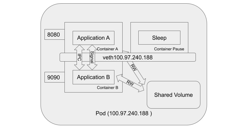
Figure 2.5 – Possible communication between containers inside a pod
As the previous diagram shows, containers inside the same pod can communicate to each other via a network, an IPC channel, a shared volume, and through signals.
Communicating between pods
Kubernetes pods are dynamic beings and ephemeral. When a set of pods is created from a deployment or a DaemonSet, each pod gets its own IP address; however, when patching happens or a pod dies and restarts, pods may have a new IP address assigned. This leads to two fundamental communication problems, given a set of pods (frontend) needs to communicate to another set of pods (backend), detailed as follows:
- Given that the IP addresses may change, what are the valid IP addresses of the target pods?
- Knowing the valid IP addresses, which pod should we communicate to?
Now, let's jump into the Kubernetes service as it is the solution for these two problems.
The Kubernetes service
The Kubernetes service is an abstraction of a grouping of sets of pods with a definition of how to access the pods. The set of pods targeted by a service is usually determined by a selector based on pod labels. The Kubernetes service also gets an IP address assigned, but it is virtual. The reason to call it a virtual IP address is that, from a node's perspective, there is neither a namespace nor a network interface bound to a service as there is with a pod. Also, unlike pods, the service is more stable, and its IP address is less likely to be changed frequently. Sounds like we should be able to solve the two problems mentioned earlier. First, define a service for the target sets of pods with a proper selector configured; secondly, let some magic associated with the service decide which target pod is to receive the request. So, when we look at pod-to-pod communication again, we're in fact talking about pod-to-service (then to-pod) communication.
So, what's the magic behind the service? Now, we'll introduce the great network magician: the kube-proxy component.
kube-proxy
You may guess what kube-proxy does by its name. Generally, what a proxy (not a reverse proxy) does is, it passes the traffic between the client and the servers over two connections: inbound from the client and outbound to the server. So, what kube-proxy does to solve the two problems mentioned earlier is that it forwards all the traffic whose destination is the target service (the virtual IP) to the pods grouped by the service (the actual IP); meanwhile, kube-proxy watches the Kubernetes control plane for the addition or removal of the service and endpoint objects (pods). In order to do this simple task well, kube-proxy has evolved a few times.
User space proxy mode
The kube-proxy component in the user space proxy mode acts like a real proxy. First, kube-proxy will listen on a random port on the node as a proxy port for a particular service. Any inbound connection to the proxy port will be forwarded to the service's backend pods. When kube-proxy needs to decide which backend pod to send requests to, it takes the SessionAffinity setting of the service into account. Secondly, kube-proxy will install iptables rules to forward any traffic whose destination is the target service (virtual IP) to the proxy port, which proxies the backend port. The following diagram from the Kubernetes documentation illustrates this well:

Figure 2.6 – kube-proxy user space proxy mode
By default, kube-proxy in user space mode uses a round-robin algorithm to choose which backend pod to forward the requests to. The downside of this mode is obvious. The traffic forwarding is done in the user space. This means that packets are marshaled into the user space and then marshaled back to the kernel space on every trip through the proxy. The solution is not ideal from a performance perspective.
iptables proxy mode
The kube-proxy component in the iptables proxy mode offloads the forwarding traffic job to netfilter using iptables rules. kube-proxy in the iptables proxy mode is only responsible for maintaining and updating the iptables rules. Any traffic targeted to the service IP will be forwarded to the backend pods by netfilter, based on the iptables rules managed by kube-proxy. The following diagram from the Kubernetes documentation illustrates this:

Figure 2.7 – kube-proxy iptables proxy mode
Compared to the user space proxy mode, the advantage of the iptables mode is obvious. The traffic will no longer go through the kernel space to the user space and then back to the kernel space. Instead, it will be forwarded in the kernel space directly. The overhead is much lower. The disadvantage of this mode is the error handling required. For a case where kube-proxy runs in the iptables proxy mode, if the first selected pod does not respond, the connection will fail. While in the user space mode, however, kube-proxy would detect that the connection to the first pod had failed and then automatically retry with a different backend pod.
IPVS proxy mode
The kube-proxy component in the IP Virtual Server (IPVS) proxy mode manages and leverages the IPVS rule to forward the targeted service traffic to the backend pods. Just as with iptables rules, IPVS rules also work in the kernel. IPVS is built on top of netfilter. It implements transport-layer load balancing as part of the Linux kernel, incorporated into Linux Virtual Server (LVS). LVS runs on a host and acts as a load balancer in front of a cluster of real servers, and any Transmission Control Protocol (TCP)- or User Datagram Protocol (UDP)-based traffic to the IPVS service will be forwarded to the real servers. This makes the IPVS service of the real servers appear as virtual services on a single IP address. IPVS is a perfect match with the Kubernetes service. The following diagram from the Kubernetes documentation illustrates this:
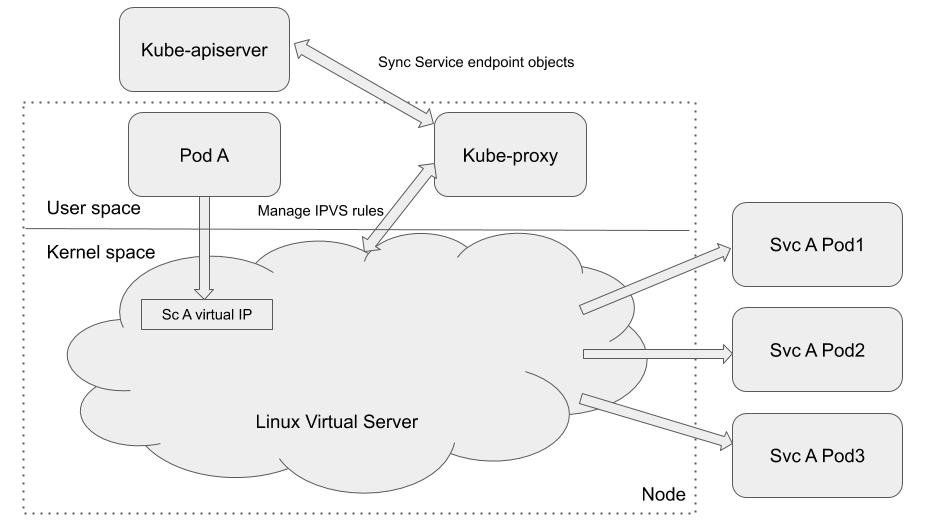
Figure 2.8 – kube-proxy IPVS proxy mode
Compared to the iptables proxy mode, both IPVS rules and iptables rules work in the kernel space. However, iptables rules are evaluated sequentially for each incoming packet. The more rules there are, the longer the process. The IPVS implementation is different from iptables: it uses a hash table managed by the kernel to store the destination of a packet so that it has lower latency and faster rules synchronization than iptables rules. IPVS mode also provides more options for load balancing. The only limitation for using IPVS mode is that you must have IPVS Linux available on the node for kube-proxy to consume.
Introducing the Kubernetes service
Kubernetes deployments create and destroy pods dynamically. For a general three-tier web architecture, this can be a problem if the frontend and backend are different pods. Frontend pods don't know how to connect to the backend. Network service abstraction in Kubernetes resolves this problem.
The Kubernetes service enables network access for a logical set of pods. The logical set of pods are usually defined using labels. When a network request is made for a service, it selects all the pods with a given label and forwards the network request to one of the selected pods.
A Kubernetes service is defined using a YAML Ain't Markup Language (YAML) file, as follows:
apiVersion: v1
kind: Service
metadata:
name: service-1
spec:
type: NodePort
selector:
app: app-1
ports:
- nodePort: 29763
protocol: TCP
port: 80
targetPort: 9376
In this YAML file, the following applies:
- The type property defines how the service is exposed to the network.
- The selector property defines the label for the Pods.
- The port property is used to define the port exposed internally in the cluster.
- The targetPort property defines the port on which the container is listening.
Services are usually defined with a selector, which is a label attached to pods that need to be in the same service. A service can be defined without a selector. This is usually done to access external services or services in a different namespace. Services without selectors are mapped to a network address and a port using an endpoint object, as follows:
apiVersion: v1
kind: Endpoints
subsets:
- addresses:
- ip: 192.123.1.22
ports:
- port: 3909
This endpoint object will route traffic for 192:123.1.22:3909 to the attached service.
Service discovery
To find Kubernetes services, developers either use environment variables or the Domain Name System (DNS), detailed as follows:
- Environment variables: When a service is created, a set of environment variables of the form [NAME]_SERVICE_HOST and [NAME]_SERVICE_PORT are created on the nodes. These environment variables can be used by other pods or applications to reach out to the service, as illustrated in the following code snippet:
DB_SERVICE_HOST=192.122.1.23
DB_SERVICE_PORT=3909
- DNS: The DNS service is added to Kubernetes as an add-on. Kubernetes supports two add-ons: CoreDNS and Kube-DNS. DNS services contain a mapping of the service name to IP addresses. Pods and applications use this mapping to connect to the service.
Clients can locate the service IP from environment variables as well as through a DNS query, and there are different types of services to serve different types of client.
Service types
A service can have four different types, as follows:
- ClusterIP: This is the default value. This service is only accessible within the cluster. A Kubernetes proxy can be used to access the ClusterIP services externally. Using kubectl proxy is preferable for debugging but is not recommended for production services as it requires kubectl to be run as an authenticated user.
- NodePort: This service is accessible via a static port on every node. NodePorts expose one service per port and require manual management of IP address changes. This also makes NodePorts unsuitable for production environments.
- LoadBalancer: This service is accessible via a load balancer. A node balancer per service is usually an expensive option.
- ExternalName: This service has an associated Canonical Name Record (CNAME) that is used to access the service.
There are a few types of service to use and they work on layer 3 and layer 4 of the OSI model. None of them is able to route a network request at layer 7. For routing requests to applications, it would be ideal if the Kubernetes service supported such a feature. Let's see, then, how an ingress object can help here.
Ingress for routing external requests
Ingress is not a type of service but is worth mentioning here. Ingress is a smart router that provides external HTTP/HTTPS (short for HyperText Transfer Protocol Secure) access to a service in a cluster. Services other than HTTP/HTTPS can only be exposed for the NodePort or LoadBalancer service types. An Ingress resource is defined using a YAML file, like this:
apiVersion: extensions/v1beta1
kind: Ingress
spec:
rules:
- http:
paths:
- path: /testpath
backend:
serviceName: service-1
servicePort: 80
This minimal ingress spec forwards all traffic from the testpath route to the service-1 route.
Ingress objects have five different variations, listed as follows:
- Single-service Ingress: This exposes a single service by specifying a default backend and no rules, as illustrated in the following code block:
apiVersion: extensions/v1beta1
kind: Ingress
spec:
backend:
serviceName: service-1
servicePort: 80
This ingress exposes a dedicated IP address for service-1.
- Simple fanout: A fanout configuration routes traffic from a single IP to multiple services based on the Uniform Resource Locator (URL), as illustrated in the following code block:
apiVersion: extensions/v1beta1
kind: Ingress
spec:
rules:
- host: foo.com
http:
paths:
- path: /foo
backend:
serviceName: service-1
servicePort: 8080
- path: /bar
backend:
serviceName: service-2
servicePort: 8080
This configuration allows requests to foo.com/foo to reach out to service-1 and for foo.com/bar to connect to service-2.
- Name-based virtual hosting: This configuration uses multiple hostnames for a single IP to reach out to different services, as illustrated in the following code block:
apiVersion: extensions/v1beta1
kind: Ingress
spec:
rules:
- host: foo.com
http:
paths:
- backend:
serviceName: service-1
servicePort: 80
- host: bar.com
http:
paths:
- backend:
serviceName: service-2
servicePort: 80
This configuration allows requests to foo.com to connect to service-1 and requests to bar.com to connect to service-2. The IP address allocated to both services is the same in this case.
- Transport Layer Security (TLS): A secret can be added to the ingress spec to secure the endpoints, as illustrated in the following code block:
apiVersion: extensions/v1beta1
kind: Ingress
spec:
tls:
- hosts:
- ssl.foo.com
secretName: secret-tls
rules:
- host: ssl.foo.com
http:
paths:
- path: /
backend:
serviceName: service-1
servicePort: 443
With this configuration, the secret-tls secret provides the private key and certificate for the endpoint.
- Load balancing: A load balancing ingress provides a load balancing policy, which includes the load balancing algorithm and weight scheme for all ingress objects.
In this section, we introduced the basic concept of the Kubernetes service, including ingress objects. These are all Kubernetes objects. However, the actual network communication magic is done by several components, such as kube-proxy. Next, we will introduce the CNI and CNI plugins, which is the foundation that serves the network communication of a Kubernetes cluster.
Introducing the CNI and CNI plugins
In Kubernetes, CNI stands for the Container Network Interface. CNI is a Cloud Native Computing Foundation (CNCF) project—you can find further information on GitHub here: https://github.com/containernetworking/cni. Basically, there are three things in this project: a specification, libraries for writing plugins to configure network interfaces in Linux containers, and some supported plugins. When people talk about the CNI, they usually make reference to either the specification or the CNI plugins. The relationship between the CNI and CNI plugins is that the CNI plugins are executable binaries that implement the CNI specification. Now, let's look into the CNI specification and plugins at a high level, and then we will give a brief introduction to one of the CNI plugins, Calico.
CNI specification and plugins
The CNI specification is only concerned with the network connectivity of containers and removing allocated resources when the container is deleted. Let me elaborate more on this. First, from a container runtime's perspective, the CNI spec defines an interface for the Container Runtime Interface (CRI) component (such as Docker) to interact with—for example, add a container to a network interface when a container is created, or delete the network interface when a container dies. Secondly, from a Kubernetes network model's perspective, since CNI plugins are actually another flavor of Kubernetes network plugins, they have to comply with Kubernetes network model requirements, detailed as follows:
- Pods on a node can communicate with all pods in all the nodes without using NAT.
- Agents such as kubelet can communicate with pods in the same node.
There are a handful of CNI plugins available to choose—just to name a few: Calico, Cilium, WeaveNet, Flannel, and so on. The CNI plugins' implementation varies, but in general, what CNI plugins do is similar. They carry out the following tasks:
- Manage network interfaces for containers
- Allocate IP addresses for pods. This is usually done via calling other IP Address Management (IPAM) plugins such as host-local
- Implement network policies (optional)
The network policy implementation is not required in the CNI specification, but when DevOps choose which CNI plugins to use, it is important to take security into consideration. Alexis Ducastel's article (https://itnext.io/benchmark-results-of-kubernetes-network-plugins-cni-over-10gbit-s-network-36475925a560) did a good comparison of the mainstream CNI plugins with the latest update in April 2019. The security comparison is notable, as can be seen in the following screenshot:

Figure 2.9 – CNI plugins comparison
You may notice that the majority of the CNI plugins on the list don't support encryption. Flannel does not support Kubernetes network policies, while kube-router supports ingress network policies only.
As Kubernetes comes with the default kubenet plugin, in order to use CNI plugins in a Kubernetes cluster, users must pass the --network-plugin=cni command-line option and specify a configuration file via the --cni-conf-dir flag or in the /etc/cni/net.d default directory. The following is a sample configuration defined within the Kubernetes cluster so that kubelet may know which CNI plugin to interact with:
{
'name': 'k8s-pod-network',
'cniVersion': '0.3.0',
'plugins': [
{
'type': 'calico',
'log_level': 'info',
'datastore_type': 'kubernetes',
'nodename': '127.0.0.1',
'ipam': {
'type': 'host-local',
'subnet': 'usePodCidr'
},
'policy': {
'type': 'k8s'
},
'kubernetes': {
'kubeconfig': '/etc/cni/net.d/calico-kubeconfig'
}
},
{
'type': 'portmap',
'capabilities': {'portMappings': true}
}
]
}
The CNI configuration file tells kubelet to use Calico as a CNI plugin and use host-local to allocate IP addresses to pods. In the list, there is another CNI plugin called portmap that is used to support hostPort, which allows container ports to be exposed on the host IP.
When creating a cluster with Kubernetes Operations (kops), you can also specify the CNI plugin you would like to use, as illustrated in the following code block:
export NODE_SIZE=${NODE_SIZE:-m4.large}
export MASTER_SIZE=${MASTER_SIZE:-m4.large}
export ZONES=${ZONES:-'us-east-1d,us-east-1b,us-east-1c'}
export KOPS_STATE_STORE='s3://my-state-store'
kops create cluster k8s-clusters.example.com
--node-count 3
--zones $ZONES
--node-size $NODE_SIZE
--master-size $MASTER_SIZE
--master-zones $ZONES
--networking calico
--topology private
--yes
In this example, the cluster is created using the calico CNI plugin.
Calico
Calico is an open source project that enables cloud-native application connectivity and policy. It integrates with major orchestration systems such as Kubernetes, Apache Mesos, Docker, and OpenStack. Compared to other CNI plugins, here are a few things about Calico worth highlighting:
- Calico provides a flat IP network, which means there will be no IP encapsulation appended to the IP message (no overlays). Also, this means that each IP address assigned to the pod is fully routable. The ability to run without an overlay provides exceptional throughput characteristics.
- Calico has better performance and less resource consumption, according to Alexis Ducastel's experiments.
- Calico offers a more comprehensive network policy compared to Kubernetes' built-in network policy. Kubernetes' network policy can only define whitelist rules, while Calico network policies can define blacklist rules (deny).
When integrating Calico into Kubernetes, you will see three components running inside the Kubernetes cluster, as follows:
- The calico/node is a DaemonSet service, which means that it runs on every node in the cluster. It is responsible for programming and routing kernel routes to local workloads, and enforces the local filtering rules required by the current network policies in the cluster. It is also responsible for broadcasting the routing tables to other nodes to keep the IP routes in sync across the cluster.
- The CNI plugin binaries. This includes two binary executables (calico and calico-ipam) and a configuration file that integrates directly with the Kubernetes kubelet process on each node. It watches the pod creation event and then adds pods to the Calico networking.
- The Calico Kubernetes controllers, running as a standalone pod, monitor the Kubernetes application programming interface (API) to keep Calico in sync.
Calico is a popular CNI plugin and also the default CNI plugin in Google Kubernetes Engine (GKE). Kubernetes administrators have full freedom to choose whatever CNI plugin fits their requirement. Just keep in mind that security is essential and is one of the decision factors. We've talked a lot about the Kubernetes network in the previous sections. Let's quickly review this again before you forget.
Wrapping up
In a Kubernetes cluster, every pod gets an IP address assigned, but this is an internal IP address and not accessible externally. Containers inside the same pod can communicate with each other via the name network interface, as they share the same network namespace. Containers inside the same pod also need to resolve the port resource conflict problem; however, this is quite unlikely to happen as applications run in different containers grouped in the same pod for a specific purpose. Also, it is worth noting that containers inside the same pod can communicate beyond the network through shared volume, IPC channel, and process signals.
The Kubernetes service helps pod-to-pod communication to be stabilized, as pods are usually ephemeral. The service also gets an IP address assigned but this is virtual, meaning no network interface is created for the service. The kube-proxy network magician actually routes all traffic to the target service to the backend pods. There are three different modes of kube-proxy: user space proxy, iptables proxy, and IPVS proxy. The Kubernetes service not only provides support for pod-to-pod communication but also enables communication from external sources.
There are a few ways to expose services so that they are accessible from external sources such as NodePort, LoadBalancer, and ExternalName. Also, you can create an Ingress object to achieve the same goal. Finally, though it is hard, we'll use the following single diagram to try to consolidate most of the knowledge we want to highlight in this chapter:
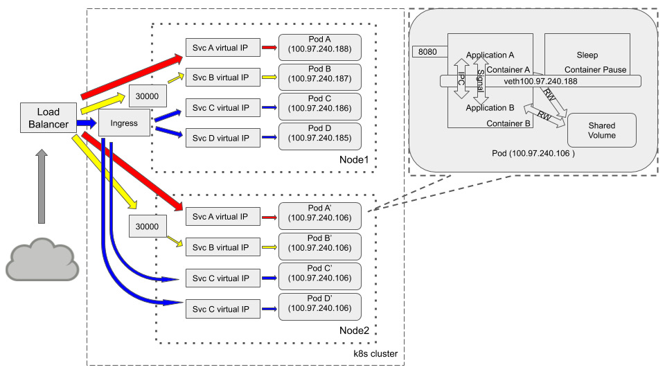
Figure 2.10 – Communications: inside pod, among pods, and from external sources
There is nearly always a load balancer sitting in front of a Kubernetes cluster. With the different service types we mentioned previously, this could be a single service that is exposed via the load balancer (this is service A), or it could be exposed via a NodePort. This is service B using node port 30000 in both nodes to accept external traffic. Though ingress is not a service type, it is powerful and cost-efficient compared to a LoadBalancer-type service. Service C and service D routing is controlled by the same ingress object. Every pod in the cluster may have an internal communication topology in the preceding callout diagram.
Summary
In this chapter, we started by discussing the typical port resource conflict problem and how the Kubernetes network model tries to avoid this while maintaining good compatibility for migrating applications from the VM to Kubernetes pods. Then, we talked about the communication inside a pod, among pods, and from external sources to pods.
Last but not least, we covered the basic concept of CNI and introduced how Calico works in the Kubernetes environment. After the first two chapters, we hope you have a basic understanding of how Kubernetes components work and how things communicate with each other.
In the next chapter, we're going to talk about threat modeling a Kubernetes cluster.
Questions
- In a Kubernetes cluster, is the IP address assigned to a pod or a container?
- What are the Linux namespaces that will be shared among containers inside the same pod?
- What is a pause container and what is it for?
- What are the types of Kubernetes services?
- What is the advantage of using Ingress other than the LoadBalancer type service?
Further reading
If you want to build your own CNI plugin or evaluate Calico more, do check out the following links: