
In this chapter, you create corridor models for subdivision roads. Corridor models for large subdivisions are often calculated to the limits of the right of ways, with no daylighting. The grading for the adjacent land parcels is created from the 3D corridor feature lines at the right of way locations.
First, you create a symmetrical assembly for modeling the tangent section of the subdivision road, and an asymmetrical assembly for modeling the cul-de-sac. The assemblies are created by adding pre-defined subassemblies for the lane, curb and sidewalk cross section elements to the assembly objects.
Next, you create a corridor model from two baselines, or alignments. The first baseline is for the centerline alignment for the tangent section of the road and references the symmetrical assembly. The second baseline for the road is the edge of pavement alignment for the cul-de-sac and references the asymmetrical assembly.
Finally, you create top and datum corridor surfaces. The corridor top surface can be used for labeling design spot elevations and grades, and can also be used to calculate pipe network rim and invert elevations. The corridor datum surface can be used to calculate earth cut and fill quantities.
This lesson describes how to create assemblies and add subassemblies to an assembly.
The assembly object, along with the horizontal and vertical alignment, is used to build the corridor model for a road, highway, railway, embankment, channel, or any cross section-based features. The subassemblies are logically designed, and respond dynamically in the design environment, making it easy to generate and evaluate design alternatives.
After completing this lesson, you will be able to:
Describe assemblies and subassemblies.
Describe the subassembly input and target parameters.
Explain how to use subassemblies to build assemblies.
Create assemblies.
Assemblies represent the typical section and are the starting point for corridor design. To create the assembly, you add subassemblies for the lanes, curbs, shoulders, and other cross-section elements.
When you create an assembly, you can make it available for future projects and other users by saving it on a tool palette, or within the drawing template (DWT) file. You can also save collections of assemblies in an assembly set.
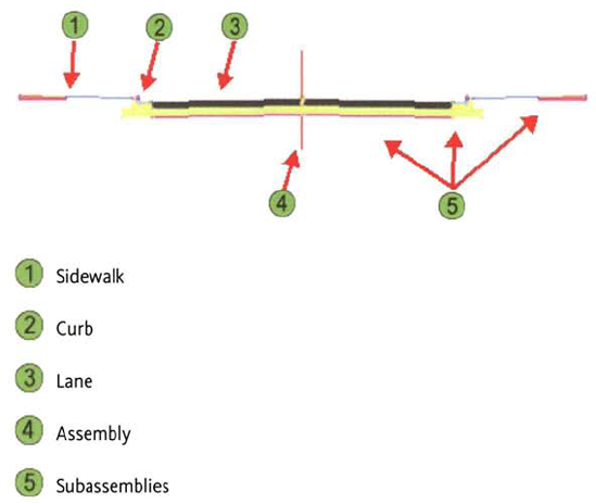
An assembly is an arrangement of cross-section features found on a roadway or other corridor, it represents a typical section of the corridor that you position with an alignment and a profile. You create an assembly and then add subassemblies for cross-section elements such as lanes, curbs, sidewalks, shoulders, and side slopes.
A subassembly is the basic building block that makes up an assembly. A subassembly is attached to one or both sides of the assembly's baseline, and subsequent subassemblies are attached to the appropriate points of the previously attached subassemblies. An assembly can be defined by attaching all of the subassemblies to one side of a baseline, and then mirroring these subassemblies to the other side of the baseline.
Subassemblies are intelligent objects that dynamically react to changes in the design environment. Each subassembly has its own set of parameters that you can modify to change its appearance or behavior. Civil 3D® provides a library of the most common, generic subassemblies that you may encounter in roadway design.
Along with using the predefined subassemblies in Civil 3D, you can also draw your own subassemblies. Civil 3D has the tools to convert your polyline shape into a subassembly. This subassembly has limited logic but can be swept down an alignment like any other subassembly. You can build your own custom subassembly with all of the parameters and functionality (or more) of those supplied in the subassembly catalog.
An assembly is made up of the following elements.
Element | Description |
|---|---|
The vertical line used as a display reference line for the assembly. | |
The point to which you attach subassemblies, and the point on the assembly attached to the horizontal and vertical alignment to create the corridor model. Also known as horizontal and vertical control. | |
Subassemblies | Cross-section element objects such as lanes, curbs, shoulders, and side slopes that you add to the assembly object. The subassemblies are added from the tool palette and attached to the assembly baseline or other subassemblies in the assembly. |
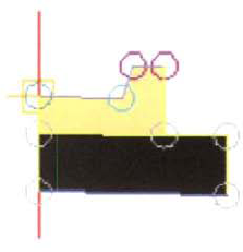
The following illustration shows a simple assembly. On either side of the baseline are subassembly objects that represent a lane, shoulder, guardrail, and cut or fill slope. In this example, the subassemblies are arranged starting from the baseline point, which is indicated by the circle with a square inside it at the midpoint of the baseline.
Subassemblies have input and target parameters that are used to change their geometric configuration.
Subassembly input parameters control the size, shape, and geometry of the subassembly. Custom subassembly input parameters can be saved on a tool palette and also specified when you add the subassembly to an assembly.
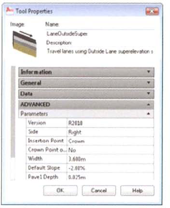
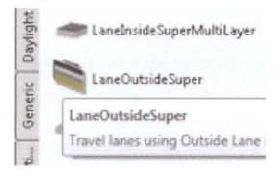
For example, the most common subassembly for modeling a lane is the LaneOutsideSuper subassembly. The LaneOutsideSuper subassembly has input parameters that set the general configuration values for the lane such as width, pavement depth, and cross fall. The default input parameters for the LaneOutsideSuper subassembly are shown in the following illustration.
Some subassemblies have required or optional target parameters. Target parameters control how the subassembly functions. Function is determined by the object the subassembly connects to (alignment, profile, or surface).
The daylighting subassemblies have required surface target parameters. You are required to specify a target surface to which the subassembly daylights.
The lane subassemblies have optional width and elevation target parameters that can be alignments and profiles. You can optionally override the lane width input parameter by targeting an alignment. This is how you vary the width of the lane in a lane taper. You can also optionally override the default slope input parameter by targeting a profile to change the lane cross fall.
For daylighting subassemblies that are used to project match slopes to surfaces, you are required to specify a surface model as the target parameter. Without the target parameter, the subassembly would not function. Lane subassemblies have optional target parameters such as lane width. A default input parameter for a iane subassembly is the lane width. The optional lane width target parameter would use another alignment to override the default lane width value. This is useful when pavement widths vary at turning lanes and lane tapers.
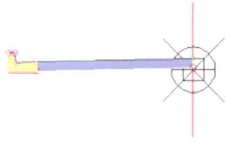
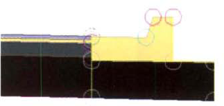
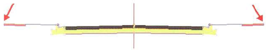
The most common subassembly to daylight to a surface is called BasicSideSlopeCutDitch. The BasicSideSlopeCutDitch subassembly has a required target parameter for a surface. When you create the corridor model with an assembly that contains BasicSideSlopeCutDitch, you must specify the target surface for the daylighting subassembly. This is shown in the following illustration.
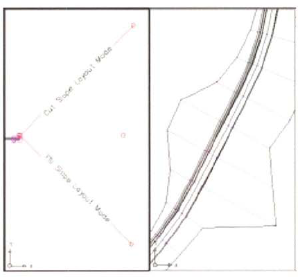
The image on the left shows the subassembly as part of the right side of an assembly, attached to a curb and gutter. The image on the right shows the result of the logic built into the subassembly when it is used in a corridor model. The width of the slope adjusts to account for changes in the terrain.
This section describes the process for creating assemblies. You create an assembly by adding the assembly to the drawing area, and then using the baseline and baseline point as a visual guide for the addition of subassemblies. Sets of subassemblies are included in the tool palettes. You can also select subassemblies from the subassembly catalog and place them on the tool palettes.
The following illustration shows a basic assembly with baseline, basic lane, and curb and gutter subassemblies.
To create an assembly you launch the Create Assembly command from the ribbon, assign a name to the assembly, and insert the assembly to the drawing. The assembly object is shown in the following illustration.
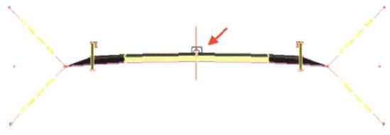
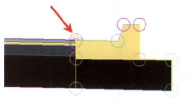
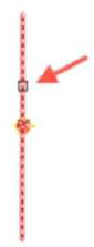
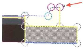
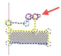
After you insert the assembly object you begin by adding the subassemblies to the assembly. The first subassemblies you add are added to the assembly and you can pick any part of the assembly object. As you move away from the assembly you need to add subassemblies to other subassemblies. You select the subassembly markers as insertion points for the other subassemblies. In the following illustration, the arrow points to one of subassembly markers.
Keep the following guidelines in mind when you create assemblies.
For every subassembly that you add to your assembly, you should read the Help file to understand how the subassembly behaves and which default settings you can modify.
Modify the default subassembly input parameters on the tool palette to suit common design configurations.
Rename the subassemblies on the tool palette to clearly indicate key geometric properties, such as width, slope, and grade.
Subassemblies added to the assembly are organized into assembly groups. When you select the assembly object to add subassemblies, a new assembly group is created. When you modify the properties of the assembly, rename the groups with indicative names, such as LEFT, RIGHT, and so on.
To create a mirror image of a subassembly or group of subassemblies, use the Mirror command, which is available on the shortcut menu.
Once the assembly is complete, you should go back and rename each of the subassemblies to give them descriptive names. This may not seem important early in a project when you have a simple assembly, but roadway jobs can get very complex. Numerous assemblies can be applied to any one alignment. It is good practice to document the components of an assembly so that other team members working on the project understand the parts and their functions.
A typical section shows the engineering details of a cross-section configuration. Typical sections are represented with assemblies in Civil 3D.
In this exercise, you create two assemblies for the Cedar Cove cul-de-sac corridor. One is required for the tangent section, and the other is required for the bulb at the end of the cul-de-sac.
Open Site Design - Assemblies and Corridorsl_create_assembly,dwg (M_ create_ assembly.dwg).
Start by configuring your workspace. To create assemblies, you need to view the AutoCAD Object Properties window with the tool palettes.
Close Toolspace.
On the command line, enter PR (Object Properties). Press ENTER.
Dock the Properties window on the left side of the screen. Right-click the title bar. Toggle Auto- Hide off.
On the command line, enter TP (Tool Palettes). Press ENTER.
Dock the Tool Palettes window on the right side of the screen. Right-click the title bar. Toggle Auto-Hide off.
The Properties window and the Tool Palettes window are both expanded and docked on either side of the screen.
Next, you configure the Tool Palettes window to show subassemblies in your unit of measure: imperial or metric.
Right-click the Tool Palettes title bar, click Civil Imperial Subassemblies (Civil Metric Subassemblies).
Next, you create the assembly for the tangent section of the cul-de-sac. This is a symmetrical assembly that models both sides of the road.
On the ribbon, Home tab, Create Design panel, click Assembly > Create Assembly.
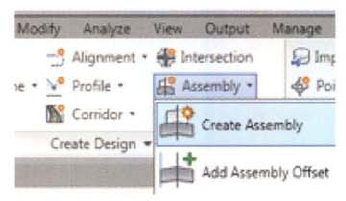
In the Create Assembly dialog box, for Name, enter 2 Lane Urban. Click OK.
At the Specify Assembly Baseline Location prompt, in the drawing, select a location to create the assembly.
The assembly object is inserted and zoomed to in the drawing.
Next, you add the lane subassemblies on the right and left sides.
On the tool palettes, click the Lanes palette.
Click LaneOutsideSuper.
In the Properties dialog box:
Click to collapse the Information, General, and Data sections.
Under Advanced Parameters, for Side, click Right.
For Width, enter 16'(4m).
Press ENTER.
At the Select a Marker Point within Assembly prompt, click the assembly.
The subassembly is attached to the assembly marker point. You see the lane structure for the right side in the drawing.
Next, you insert the left lane.
In the Properties dialog box, for Side, click Left.
At the Select a Marker Point with Assembly prompt, click the assembly in the same location to insert the left lane.
Next, you insert the curb and gutter subassemblies.
On the tool palettes, click the Curbs palette.
Click UrbanCurbGutterGeneral.
In the Properties dialog box, for Side, click Right.
At the Select a Marker Point within Assembly prompt, click the subassembly marker point at the top of pavement edge location on the right side.
The UrbanCurbGutterGeneral subassembly is inserted on the right side.
In the Properties window, for Side, click Left.
At the Select a Marker Point within Assembly prompt, click the subassembly marker point at the top of pavement edge location on the left side.
Note
if you make a mistake, you can use the AutoCAD Erase command to erase the subassembly and try again.
Next, you insert the sidewalks.
On the Curbs palette, click UrbanSidewalk.
In the Properties dialog box:
For Side, click Right.
For Inside Boulevard Width, enter 7' (2.4m).
For Sidewalk Width, enter 4'(im).
For Outside Boulevard Width, enter 1'(.5m).
At the Select a Marker Point within Assembly prompt, click the subassembly marker point on the top and back of curb on the right side.
The sidewalk is added to the assembly.
In the Properties dialog box, for Side, click Left.
At the Select a Marker Point within Assembly prompt, click the subassembly marker point on the top and back of curb on the left side.
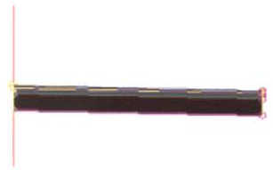
You now have sidewalks on both sides of the assembly. The completed assembly appears as follows.
Next, you create the assembly for the bulb section of the cul-de-sac.
On the ribbon, Home tab, Create Design panel, click Assembly > Create Assembly.
In the Create Assembly dialog box, for Name, enter Half Section. Click OK.
At the Specify Assembly Baseline Location prompt, click below the 2 Lane Urban assembly.
On the Curbs palette, click UrbanCurbGutterGeneral.
In the Properties dialog box, for Side, click Right.
At the Select Marker Point within Assembly prompt, click the assembly baseline to insert the subassembly.
On the Curb palette, click UrbanSidewalk.
In the Properties dialog box:
For Side, click Right.
For Inside Boulevard Width, enter 7' (2.4m).
For Sidewalk Width, enter 4' (1m).
For Outside Boulevard Width, enter 1' (0.5m).
At the Select Marker Point within Assembly prompt, click the subassembly marker on the top of the back of the curb.
The sidewalk is inserted.
Next, you add a lane on the left side of the assembly. This lane forms the center paved portion of the cul-de-sac when the assembly is processed around the pavement edge baseline in the cul-de-sac.
Click the Lanes palette.
Click LaneOutsideSuper.
In the Properties dialog box:
For Side, click Left.
For Width, enter 16' (4m).
At the Select Marker Point within Assembly prompt, click the assembly. The lane subassembly is inserted.
The Half Section assembly appears as shown.
Press ESC to cancel the command.
Close the Properties dialog box.
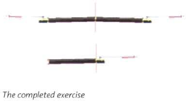
The completed exercise appears as follows.
Close the Tool Palettes and Properties windows.
Open the Toolspace window.
Close the drawing. Do not save the changes.
This lesson describes the components of a corridor model, and how to use them to build a simple model of a residential subdivision road with a cul-de-sac.
You can use corridor models to represent any road, rail, channel, or berm design that has typical cross- section features. When you create a corridor model, you create a single object that includes all the design components and input parameters for a road or other type of feature created from a typical cross-section.
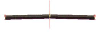
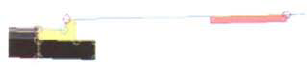
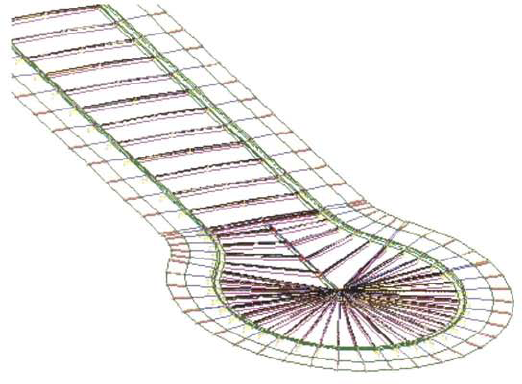
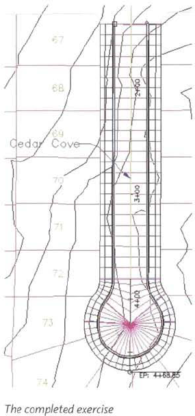
A completed corridor model for a residential subdivision road with a cul-de-sac is shown in the following illustration.
After completing this lesson, you will be able to:
Describe a corridor model and list its components.
Explain the process for creating a subdivision corridor model.
Create a corridor model for a subdivision road with a cul-de-sac.
When you create a corridor, you can create complex models for transportation facilities such as roads, highways, and railways by adding corridor regions or referencing more than one alignment baseline. Almost any condition that your design may call for can be modeled by using the corridor functionality.
A simple corridor creates a model based on a single alignment (baseline), profile, and assembly. You can make corridor models more complex by adding additional alignments (baselines), or by creating regions that use different assemblies. You can enhance and expand the basic corridor configuration to accommodate a wide variety of designs.
A corridor model is a three-dimensional representation of the design for a roadway, railway, or other transportation facility. Corridors can also be used to model channels, berms, and any other civil engineering feature that can be represented with a typical section. You create a corridor model with an alignment, a layout profile, and an assembly. By incorporating constraints and rules into the corridor design, you can manage and control how the corridor model interacts with the terrain and other alignments and profiles.
Many large subdivision designs are created based on developing an interim grading surface that accounts for site topography and drainage constraints. The subdivision roads are usually the spine of the subdivision and designed first. The layout profiles are designed to match surface profiles generated from an interim grading surface.
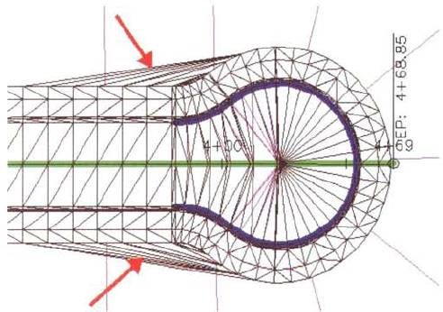
Unlike road and highway corridor models, the assemblies used to create subdivision corridor models typically do not include daylighting subassemblies and therefore do not interact with surface models. Subdivision corridor models are usually calculated up to the right-of-way and are essentially floated through space along the horizontal and vertical alignments.
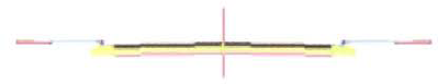
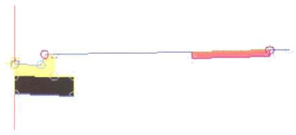
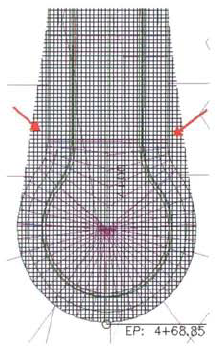
A typical assembly for a subdivision corridor model is shown in the following illustration. The right-of- ways are indicated by the arrows.
In addition to the alignment, layout profile, and the assembly, corridors are also comprised of feature lines, regions, and baselines.
Feature lines are the longitudinal lines along the corridor that are used to represent typical cross-section points such as road crowns, pavement edges, gutter flow lines, sidewalk edges, and daylighting lines. Feature lines are part of the corridor model and are created by connecting the subassembly points of the corridor assembly.
Corridor regions are independent station ranges to which you can apply different assemblies to model differing cross-section configurations.
The baseline is the alignment that is used to control the creation of a corridor model. A corridor model can be constructed from several baselines. A corridor for a subdivision road with a cul-de-sac uses a centerline alignment baseline for the main section of the road, and an edge of pavement alignment baseline for the cul-de-sac.
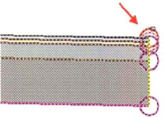
The following illustration shows feature lines on a corridor model for a subdivision road with a cul-de- sac.
The following illustration shows three centerline alignments that represent an on-ramp (entering from the top- right corner), an off-ramp, and the two-lane road where the two ramps join. The alignments for the on-and off-ramps end at precisely the same location as the beginning of the two-lane segment, which creates a continuous corridor from the three segments. The illustration shows the same alignments after a corridor is created. Different assemblies are applied along the alignments to create a single corridor with lanes and ditches that merge together seamlessly. Each alignment is associated with the corridor model by using a different baseline entry in the corridor properties. The illustration shows a transition between regions in a corridor. The upper region of the corridor uses an assembly with a plain shoulder. The lower region uses a similar assembly that has a curb and gutter instead of the paved shoulder.
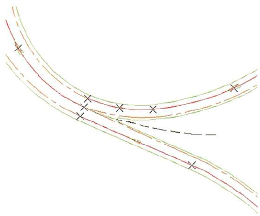
The following illustration shows the same alignments after a corridor is created. Different assemblies are applied along the alignments to create a single corridor with lanes and ditches that merge together seamlessly. Each alignment is associated with the corridor model by using a different baseline entry in the corridor properties.
The following illustration shows a transition between regions in a corridor. The upper region of the corridor uses an assembly with a plain shoulder The lower region uses a similar assembly that has a curb and gutter instead of the paved shoulder.
When you create 3 corridor, it is displayed on the Prospector tool under the Corridors collection. You can edit the corridor later to add more complex features such as baselines and regions.
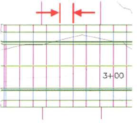
To create a corridor model, you must specify an alignment, a vertical alignment, and an assembly. The assembly is processed along the horizontal alignment at a prespecified "assembly insertion frequency," which is the increment along the alignment where the assembly is inserted to create the corridor. This is shown in the following illustration.
The assembly insertion frequency is not related to the increment at which cross-sections can be created, and can be changed when you modify the properties of the corridor.
The alignment you specify when you create the corridor is called a baseline. The baseline is the alignment that is used to control the creation of a corridor model. You can specify multiple baselines when creating a corridor. This is how you create a corridor that incorporates a cul-de-sac. Complex corridor models can incorporate several baselines.
If the assembly you use has subassemblies that require target assignments, such as the daylight subassemblies, when you create the corridor you have the option to specify the targets. The target for a daylight subassembly would be a surface model. Typically, subdivision assemblies do not use daylight subassemblies.
Corridor regions are segments of a corridor that are defined by an independent station range and assembly. When you use multiple corridor regions, you can use multiple assemblies to model the corridor over a different station range. This makes it easy to model widely variable cross-section configurations with a single corridor model.
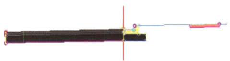
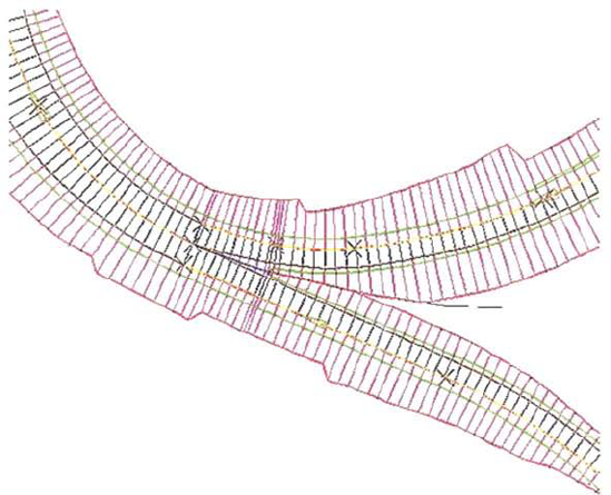
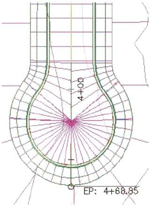
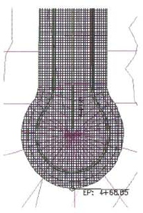
A corridor model for a subdivision road with a cul-de-sac incorporates two baselines. The first baseline controls the creation of the corridor for the main part of the road and is usually the road centerline alignment. The second baseline controls the creation of the corridor cul-de-sac and is usually the edge of pavement or gutter alignment around the cul-de-sac. This is shown in the following illustration.

The assembly that you process along the first baseline represents a symmetrical cross-section up to the right-of-way locations. The assembly you process along the second baseline is an asymmetrical cross-section with the baseline at the edge of pavement location. The assembly baseline is indicated by the arrow in the following illustration.
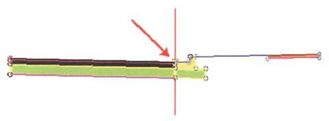
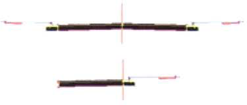
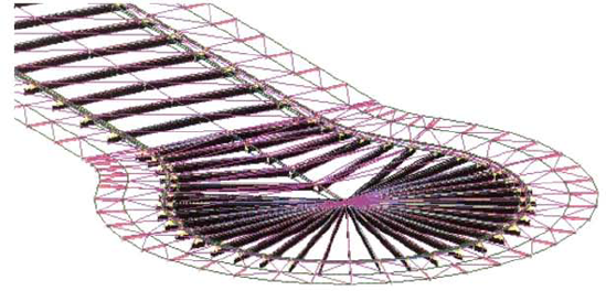
The lane subassembly in the cul-de-sac assembly has a fixed width. The width of the lane subassembly and the elevation of the inside crown is overridden by assigning the optional alignment and profile target to the centerline alignment and profile of the cul-de-sac alignment. This essentially stretches the lane back to the centerline alignment and elevation in the cul-de-sac. The following illustration shows the completed cul-de-sac without targets assigned to the lane subassembly.
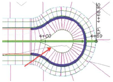
When you assign targets to the lane subassembly on the asymmetrical assembly for the second corridor region, the lane stretches back to the centerline alignment location and elevation. This is shown in the following illustration.

Keep the following guidelines in mind when you create corridor models.
When you create a corridor model, you can use the Create Corridor command or the Create Simple Corridor command. Both commands result in the same object. However, the Create Simple Corridor commands offers fewer input options to create the corridor.
When you create the corridor model, make sure that you specify a station range for each region so that you can assign the appropriate target. Ensure that you have layout profile data for the station range over which the corridor regions are created.
Use representative naming conventions for alignments, profiles, corridors, and corridor regions. This makes it easier to create and manage corridor data.
In this exercise, you create a corridor model for a subdivision road with a cul-de-sac.
Open Site Design - Assemblies and Corridorsl_create_corridor.dwg (M_create_corridor.dwg).
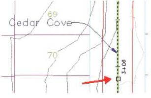
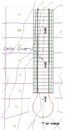
Zoom in to the Cedar Cove alignment on the east side of the site.

You begin by modeling the tangent section of the corridor.
On the ribbon, Home tab, Create Design panel, click Corridor > Create Corridor.
At the Select a Baseline Alignment prompt, in the drawing area, click the Cedar Cove centerline alignment.
At the Select a Profile prompt, press ENTER.
In the Select a Profile dialog box, click Cedar Cove - FG. Click OK.
At the Select an Assembly prompt, press ENTER.
In the Select an Assembly dialog box, click 2 Lane Urban. Click OK.
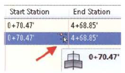
In the Create Corridor dialog box:
For Corridor Name, enter Cedar Cove.
In the Name column, click RG −2 Lane Urban - (1). Change the name to Tangent.
In the Start Station column, click the Select Station.
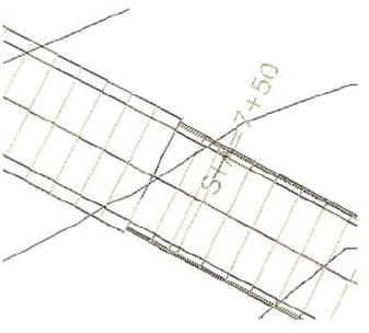
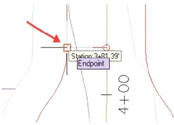
At the Specify Station along Alignment prompt, in the drawing area, snap to the endpoint of the edge of the pavement alignment to the right of Parcel 67.

The Tangent region of the corridor starts at this location.
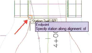
In the Create Corridor Dialog box, for Tangent, in the End Station column, click the Select Station.
At the Specify Station along Alignment prompt, snap to the endpoint of the first arc at the northwest end of the cul-de-sac.
The Tangent region of the corridor ends at this location.
In the Create Corridor Dialog box, for Tangent, in the Frequency column, click the ellipse.
In the Frequency to Apply Assemblies dialog box, under Apply Assembly:
For Along Tangents, enter 10 (5 m).
For Along Curves, enter 10 (5 m).
For Along Spirals, enter 10 (5 m).
For Along Profile Curves, enter 10 (5 m).
The assembly will be processed every 10' (5 m) along this region to calculate the corridor.
Click OK twice to close the dialog boxes.
The corridor for the tangent region of Cedar Cove is created.
Next, you model the cul-de-sac.
In the drawing area, select the corridor. On the ribbon, click Corridor Properties.
In the Corridor Properties - Cedar Cove dialog box, Parameters tab, click Add Baseline.
In the Create Corridor Baseline dialog box, for Horizontal Alignment, click Cedar Cove EP. Click OK.
For Cedar Cove EP - (2):
Click in the Profile column.
In the Select a Profile dialog box, click Cedar Cove EP - FG.
Click OK.
Right-click Baseline - Cedar Cove EP - (2). Click Add Region.
In the Create Corridor Region dialog box, for Assembly, select Half Section assembly from the list. Click OK.
Expand Baseline - Cedar Cove EP - (2).
Double-click RG - Half Section - (1). Change the name to Cul-de-sac.
For the Cul-de-sac region, under Start Station, click Select Station.
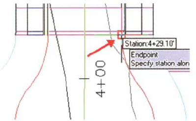
At the Specify Station along Alignment prompt, snap to the endpoint of the first arc on the cul- de-sac.
For the Cul-de-sac region, click Select Station in the End Station column.
At the Specify Station Along Alignment prompt, snap to the endpoint of the last arc on the cul- de-sac.
For the Cul-de-sac region, under Frequency, click the ellipse.
In the Frequency to Apply Assemblies dialog box, under Apply Assembly:
For Along Tangents, enter 5 (2 m).
For Along Curves, enter 5 (2 m).
For Along Spirals, enter 5 (2 m).
For Along Profile Curves, enter 5 (2 m).
Click OK twice to close the dialog boxes.
The corridor is constructed into the cul-de-sac. Notice that the cul-de-sac does not extend back to the center of Cedar Cove. The lane width for the half section is too small.
In the drawing area, select the corridor. Right- click, click Corridor Properties.
In the Corridor Properties - Cedar Cove dialog box, Parameters tab, for the Cul-de-sac region, under Target, click the ellipse.
You use target mapping to stretch the LaneOutsideSuper assembly to the Cedar Cove centerline and profile. This completes the design to the center of the cul-de-sac.
In the Target Mapping dialog box, for Width Alignment, click in the Object Name cell.
In the Set Width or Offset Target dialog box:
For Select Object Type to Target, click Alignments.
Under Select Alignments, click Cedar Cove.
Click Add.
Click OK.
For Outside Elevation Profile, click in the Object Name cell.
In the Set Slope or Elevation Target dialog box:
For Select Object Type to Target, click Profiles.
For Select an Alignment, click Cedar Cove.
For Select Profiles, click Cedar Cove - FG.
Click Add.
Click OK.
The Target Mapping dialog box, Object Name column appears as follows.

Click OK twice to close the dialog boxes.
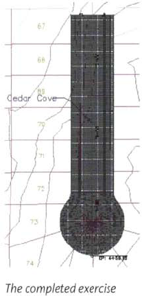
The Cedar Cove corridor with cul-de-sac is reprocessed and is now complete.
Close the drawing. Do not save the changes.
This lesson describes how to create corridor surfaces from corridor models.
Corridor surfaces are useful for design and construction tasks. You can use corridor surfaces to calculate earth cut and fill quantities, label spot elevations and slopes, and generate construction staking data. Corridor surfaces are dynamic and automatically update when the corridor changes.
After completing this lesson, you will be able to;
Describe corridor surfaces.
Describe the process for creating corridor surfaces.
Create a corridor surface.
After you create a corridor model, you can create corridor surfaces. You can use a corridor surface for earth cut and fill volume calculations, finished grade elevation and slope labels, and for calculating pipe network structure rim and invert elevations.
A corridor surface represents a finished layer of a corridor design. It is a Civil 3D surface object created from the links or feature lines of a corridor model. Corridor surfaces are reactive surfaces that are displayed in the Surfaces collection on the Prospector tab of the Toolspace window. Corridor surfaces can be displayed, annotated, and sampled just like regular surfaces.
You create a corridor surface boundary to contain the triangulation of points within the limits of the boundary. To automatically create a corridor surface boundary, you modify the properties of the corridor.
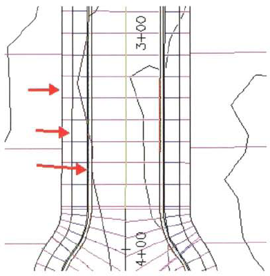
For a residential subdivision road corridor, the surface boundary is at the right-of-way line. The following illustration shows a corridor top surface of a residential subdivision road without a boundary defined. The arrows point to the triangulation lines that are outside the surface boundary.
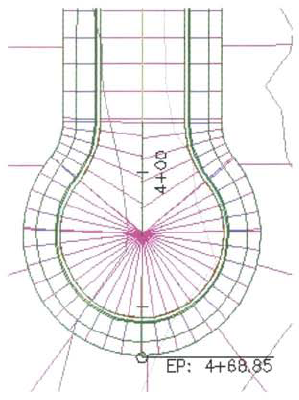
The following illustration shows the same corridor top surface with the boundary defined. In this case, the triangulation lines are contained by the boundary of the corridor surface.

You use corridor data to create a corridor surface. When you create a corridor surface, you can use either the subassembly links or the corridor feature lines as corridor data. The most common corridor data is the subassembly links.
To create a corridor surface you modify the corridor properties and use commands available on the Surfaces tab of the Corridor Surface dialog box. The most common corridor surfaces incorporate the Top subassembly links and the Datum subassembly links.
Top Corridor Surface Corridor surfaces using the Top subassembly links can be used for the following:
Creating finished design contours.
Labeling finished spot elevations and slopes.
Creating finished grade construction staking data.
Corridor surfaces using the Datum subassembly links can be used for the following:
Calculating earth cut and fill quantities.
Creating subgrade construction staking data.
In this exercise, you create a top corridor surface for the Cedar Cove corridor.
Open Site Design - Assemblies and Corridorsl_corridor_surface.dwg (M_corridor_surface.dwg).
In Prospector, click to expand Corridors. Right- click Cedar Cove. Click Properties.
In the Corridor Properties - Cedar Cove dialog box, Surfaces tab:
Click Create a Corridor Surface, the first icon on the left.
Change the surface Name to Cedar Cove TOP.
Click in the Surface Style column.
In the Pick Corridor Surface Style dialog box, click Grid. Click OK.
Under Add Data, verify Data Type is set to Links and Specify Code is set to Top.
Click Add Surface Item (plus sign).
Click OK.
You create the surface from the top corridor links. Links connect the points on the corridor assembly.
The following illustration shows a surface representing the top of the Cedar Cove corridor. Notice that the surface extends beyond the limits of the corridor near the cul-de-sac. This occurs because a boundary has not been defined for the surface.
Next, you add boundaries to contain the surface within the limits of the corridor.
In Prospector, under Corridors, right-click the Cedar Cove. Click Properties.
In the Corridor Properties - Cedar Cove dialog box, Boundaries tab, right-click Cedar Cove TOP. Click Corridor Extents as Outer Boundary. Click OK.
The corridor rebuilds with the Cedar Cove top surface displayed with boundaries.
Repeat the process and create a corridor surface called Cedar Cove DATUM, using the Datum links.
Close the drawing. Do not save the changes.