
This chapter describes how you work with alignments as they relate to residential subdivision design projects. Alignments and road corridor models form the backbone for the subdivision design in that they usually set the grade for the parcels adjacent to the subdivision roads. The Creating Alignments from Objects lesson describes how you create alignments from polylines. The Labeling Alignments and Creating Tables lesson describes how you reduce the amount of annotation that appears on a subdivision plan by creating tag labels and showing the data in a corresponding table.
This lesson describes how you create subdivision road alignments from AutoCAD® entities such as lines, arcs, and polylines. Alignments are a critical component of all subdivision and roadway projects that have linear corridor design elements such as residential and collector roads. Alignments can also be used with creeks and rivers for floodplain analysis and channel design.
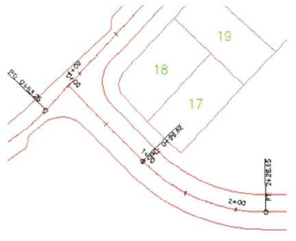
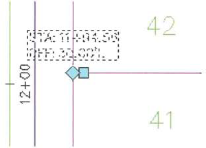
The following illustration shows two intersecting alignments:
After completing this lesson, you will be able to:
Describe alignments and their properties.
List the guidelines for creating alignments.
Create alignments using objects.
The subdivision layout process is an iterative process where a developer, or the developer's engineer, strives to maximize the use of the land based on zoning, parcel layout, and road design criteria.
In many circumstances, the parcel outline for the subdivision is designed first, and then handed off to a designer who is tasked with designing the roads in the subdivision. Road designers often offset parcel right-of-way lines, polylines, and arcs to create the horizontal alignment geometry for the subdivision roads.
This geometry is converted to polylines, which are then used to create alignment objects for the subdivision roads.
Alignments are a series of coordinates, lines, curves, and spirals used to represent the centerline of linear features such as roads, edges of pavement, sidewalks, and rights-of-way. Alignments can also be used to represent the centerline of a railway, channel, or stream.
Horizontal alignments in subdivisions are usually not very complex and consist mostly of tangents and curves. In some instances lane tapers are modeled using alignments to create acceleration, deceleration, and turn lanes at intersection locations. Subdivision road centerline alignments are most often created by offsetting right-of-way lines by half the width of the right-of-way. Common commands such as trim, edit, extend, and fillet are used to create the alignment geometry from AutoCAD entities.
Once the geometry is in place, the Polyline Edit command can be used to join the lines and arcs together to form a continuous polyline representing the alignment. The direction of the polyline does not matter because once you create the alignment, you can reverse the direction of the alignment. You can also create alignments from AutoCAD line and arc entities.
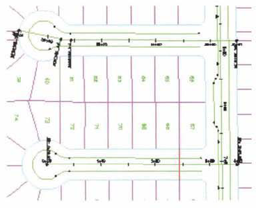
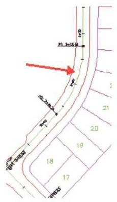
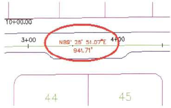
Alignments for residential subdivision roads are shown in the following illustration.
Keep the following guidelines in mind when you create alignments.
The direction of the polyline is not important, as you can reverse the direction of an alignment during the alignment creation process. You can also reverse the alignment direction after it has been created.
When you create an alignment from a polyline with no curves, or from lines, you can automatically add curves between the tangents.
You can assign a value to the starting station of the alignment, which is the start point of the polyline, line, or arc. Alignment station reference points and base stationing values can be adjusted later.
Alignments can either be independent or included in a site. Use alignments in a site if you want them to interact with other objects in the site, or if you want to use sites to organize the alignments.
In this exercise, you create alignments using polylines.
You create an alignment from the polyline running south to north on the west boundary of the site, and from the polyline running west to east on the south boundary of the site.
Open Site Design - Alignmentsl_alignment_from_polyline.dwg (M_ alignment_from_ polyline.dwg).
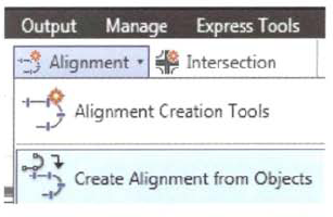
On the ribbon, Home tab, Create Design panel, dick Alignment > Create Alignment from Objects.
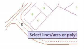
At the Select Lines/Arcs or Polylines prompt, click near the left end of the polyline running west to east on the south end of the site. Press ENTER.
The stationing of the alignment begins at the end of the polyline closer to where you select it, or you can change the location.
Press ENTER to accept the alignment direction (west to east).
In the Create Alignment from Polyline dialog box:
For Name, enter Oak Street.
For Site, click <None>.
For Type, ensure Centerline is selected.
For Alignment Style, click Proposed.
For Alignment Label Set, click All Labels.
Under Conversion Options, clear the Add Curves Between Tangents check box.
Under Conversion Options, click Erase Existing Entities. This option removes the original polyline once the alignment is created.
On the Design Criteria tab:
Notice that you can assign a design speed and use criteria-based design. This means that you can check alignments for minimum curvature and assign superelevation from design criteria files.
Click OK.
The alignment is created and labeled.
Repeat steps 4 and 5 for the road running south to north on the west side of the site. This road is called 8th Avenue, and the direction of stationing increases to the north.
In Toolspace, on the Prospector tab:
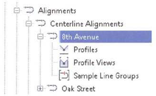
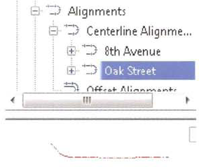
Click to expand Alignments, Centerline Alignments, 8th Avenue.
Notice that each alignment can have multiple profiles, profile views, and sample line groups.
Right-click 8th Avenue, Click Properties.
In the Alignment Properties - 8th Avenue dialog box, Information tab, for Object Style, click Existing. Click OK.
The alignment display updates.
Repeat steps 7 and 8 to create the south to north Oak Street alignment.
Next, you view the object styles in the Settings tab.
In the Settings dialog box:
Click to expand Alignment, Alignment Styles.
Right-click Existing. Click Edit.
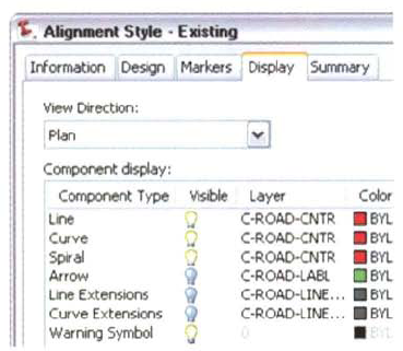
In the Alignment Style - Existing dialog box, on the Display tab, review the visible component settings.
Note that only the Line, Curve, and Spiral components are visible and are set to the C- ROAD-CNTR layer, which is red.
Also notice the Warning Symbol component. This is used to display a warning in the drawing area if you have used criteria-based design and violated the design criteria.
Click Cancel.
Repeat steps 11 and 12 and review the proposed alignment style. Note the alignment style differences.
Next, you preview the alignment objects in Prospector.
In Prospector: Click to expand Alignments, Centerline Alignments.
Click Oak Street. In the item view area you should see a preview of the alignment.
If you do not see the preview, ensure that the preview icon at the top of Prospector is on. Right-click Alignments. Ensure Show Preview is enabled.
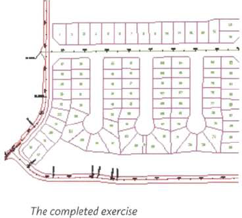
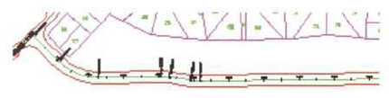
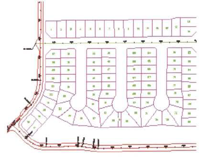
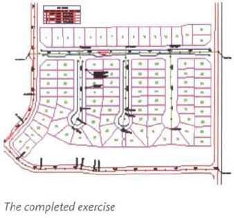
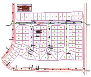
The finished drawing appears as follows.
Close the drawing. Do not save the changes.
This lesson describes how you label horizontal alignments and create tables that show the alignment data. Horizontal alignments are made up of segments, which are lines, arcs, or spirals. There are a number of powerful labeling tools in Civil 3D® for labeling horizontal alignment geometry, either on the alignment itself or in a table.
When you edit or change an alignment, associated labels and tables automatically update to reflect the new alignment geometry.
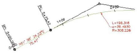
The following illustration shows alignment geometry with segment labels.
After completing this lesson, you will be able to:
Describe alignment tag labels.
List the guidelines for creating alignments and tables.
Label alignments and create a table.
When plans become difficult to read because of too many geometry alignment labels, you C3n create tag labels for the alignment segments and show the geometry in a corresponding table.
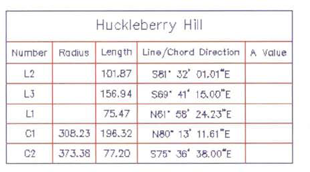
After adding tag labels, you create an alignment table that references the tags. You can create a line, curve, spiral, or segmental table that shows the geometry for the entire alignment. The table can be dynamic. When you edit the horizontal alignment or change the station reference point, the data in the table automatically updates to reflect the new geometry.
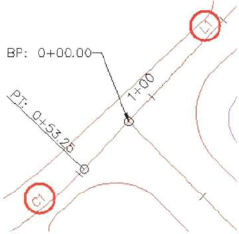
To create tag labels, you select a tag label style from the Add Labels dialog box as shown in the following illustration.
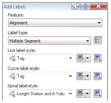
There are a number of different label types that you can add to a horizontal alignment. To label alignment geometry, you can either label single segments or multiple segments. The multiple segment option enables you to label all segments for the entire alignment. When you choose the label type, you can then specify the corresponding label style.
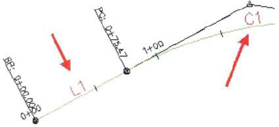
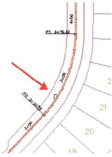
An alignment with tag labels is shown in the following illustration.
Keep the following guidelines in mind when labeling alignments.
In this exercise, you create alignment tag labels and an alignment table.
Open Site Design - Alignmentsl_label_alignments.dwg (M_label_alignments.dwg).
First, you review the labels.
In Toolspace, Settings tab:
Click to expand Alignment, Label Styles.
Review the variety of label styles. You can create or modify styles in any of these categories. You can also individually label segments of alignments or points either on or offset from the alignment.
Click to expand Label Sets.
Right-click Label Sets. Click New.
In the Alignment Label Set - New Alignment Label Set dialog box:
Click the Labels tab. Review the choices under Type. These are the types of alignment labels you can include in a label set.
With Type set to Major Stations, click Add.
The Parallel with Tick Major Station label style is added to the label set.
Change Type to Minor Stations. Click Add.
The Tick Minor Station label style is added to the label set. Note that you can specify the increment for the major and minor station labels. You can build your own customized label set.
Click Cancel.
Alignment label sets are assigned to an alignment when you create it.
On the ribbon, Home tab, click Alignment > Alignment Creation Tools.
In the Create Alignment - Layout dialog box:
Review the Alignment Label Set list. When you create an alignment by layout, you should specify the alignment label set.
Click Cancel.
In the drawing area, select the 8th Avenue alignment. This is the north - south running alignment on the west side of the subdivision. Right-click and then click Edit Alignment Labels.
In the Alignment Labels dialog box:
Notice that you can import a predefined label set.
For Major Station Increment, enter 50' (50 m).
For Minor Station Increment, enter 10' (20 m).
Click in the Station Equations row, click Delete (red 'X').
Click in the Profile Geometry Points row, click Delete (red 'X').
Click Save Label Set.
In the Alignment Label Set dialog box, Information tab, for Name, enter Maj (50) Min (10) and GP.
Click OK twice.
The labeling of 8th Avenue has changed. You have also created a new label set.
Next, you add alignment station and offset labels.
In the drawing area, zoom in and click the 8th Avenue alignment.
On the contextual ribbon select Add Labels > Add Alignment Labels.
This is the same Add Label dialog box used for other features.
In the Add Labels dialog box:
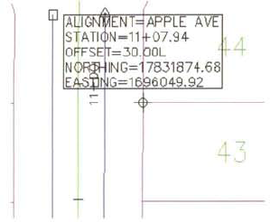
For Label Type, click Station Offset - Fixed Point.
For Station Offset Label Style, click Station Offset and Coordinates.
Click Add.
This command places a label that shows a station and offset from an alignment, and the coordinates of that point, for a location such as a fire hydrant or parcel boundary.
At the Select an Alignment prompt, select the Apple Ave centerline alignment.
Apple Ave is the western cul-de-sac alignment.
Move the mouse near the west endpoint of the parcel boundary between parcels 43 and 44.
When prompted to Select Point, use the endpoint object snap and select a parcel corner.
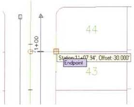
A station offset is created.
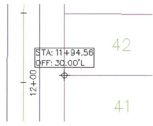
In the Add Labels dialog box, for Station Offset Label Style, click Station and Offset. Click Add.
At the Select Alignment prompt, click Apple Ave.
At the Select Point prompt, move the cursor south and near the west endpoint of another parcel segment. Snap to the end point.
Press ESC. A different station offset label is created.
Next, you experiment with the label dragged state display properties.
In the drawing area, select a station and offset label.
Hover the mouse over each grip. Notice the tooltips.
You use the Move Point Being Labeled grip (diamond shape) to reposition the label and the label point.
You use the Drag Label grip (square shape) to drag the label away from the point it is labeling. A pointer is added to the point label to show the point being labeled.
Experiment with the Slide Label and Drag Label grips on the Station and Offset labels you created.
Next, you label the alignment segments.
In the Add Labels dialog box:
For Label Type, click Single Segment. This command is used to label an individual segment(line, curve, or spiral) of an alignment.
For Line Label Style, click Bearing over Distance.
Click Add.
At the Select Point on Entity prompt, click a line segment on the Orchard Road alignment. This is the alignment that intersects the three cul-de-sac alignments.
Press ESC.
Click the line label on the alignment and experiment with the grips.
Next, you create tag labels on the alignment.
In the Add Labels dialog box:
For Label Type, click Multiple Segment.
For Line Label Style, click Tag.
For Curve Label Style, click Tag.
Click Add.
Under Select Alignment, click 8th Avenue.
This is the south-to-north running alignment on the west side of the site.
The tag labels are created.
Press ENTER.
Click Close to close the Add Labels dialog box.
Next, you create a table to show the alignment data.
In the drawing area, select the 8th Avenue alignment.
On the contextual ribbon, select Add Tables > Add Segments.
In the Alignment Table Creation dialog box, for Select Alignment, click 8th Avenue. Click OK.
At the Select Upper Left Corner prompt, click in the drawing to create the table.
The table is created showing the alignment data for the 8th Avenue alignment.
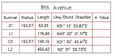
The finished drawing appears as follows.
Close the drawing. Do not save the changes.