
In this chapter, you layout and design a storm sewer pipe network for a new subdivision design. You can layout storm sewers, sanitary sewers, watermain systems, electrical ducting, and any other types of subsurface utilities using pipe network functionality in Civil 3D®. The lessons in this chapter guide you through the process for creating, editing, and annotating a storm sewer pipe network. You also use the Hydraflow Storm Sewers Extension to size pipes and calculate invert elevations from flow data.
Pipe networks are created from pipe and structure parts that exist in a parts list. You create a parts lists containing the pipe and structure parts that you would regularly use for your company or client projects. Pipe and structure parts are added to the parts list from the pipes and structures parts catalog. You typically create a separate parts list for storm sewer, sanitary sewer, and watermain systems. You save the parts list in your company or client drawing template (DWT) file to provide users access to the standardized pipe and structure parts that you regularly use on your projects.
When you create a pipe network, predefined rules are applied to calculate the invert elevations and the slopes of the pipes in pipe network. You create a pipe network by selecting the locations of the structure and pipes in plan view. Structure rim elevations are calculated from a finished design surface. Invert elevations are automatically calculated using a combination of minimum/maximum cover and minimum/maximum slope criteria.
Pipe network invert elevations and slopes can be edited either graphically or in a table. When you make changes to elevations and slopes, the graphical display and the annotation of the pipe networks automatically update. You can also use grips to edit the position of pipes and structure graphically in the drawing area. When you move a structure in plan view, the display of the pipe network in the profile view automatically updates.
You use the Hydraflow Storm Sewers Extension to calculate pipe diameters and invert elevations based on inputting flow data. You export a pipe network layout from Civil 3D. Then, you import the data to Hydraflow Storm Sewers Extension, input the flows, and calculate pipe sizes and invert elevations. Finally, the updated data is exported back to Civil 3D.
After completing this chapter, you will be able to:
Create a pipe network that represents a storm sewer design in a subdivision.
Draw pipe network parts in profile views and edit the pipe network.
Label pipe networks in plan and profile view.
Use the Hydraflow Storm Sewers Extension to calculate pipe diameters and invert elevations.
This lesson describes pipe networks and how you add pipes and structures to a pipe network in plan view.
You create a pipe network to model storm sewer, sanitary sewer, and watermain systems. By creating a 3D model of a pipe network, you can quickly explore different design alternatives and check for interferences with other subsurface features.
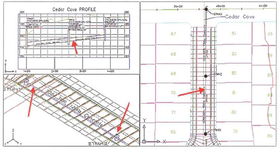
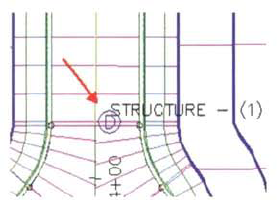
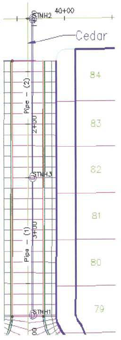
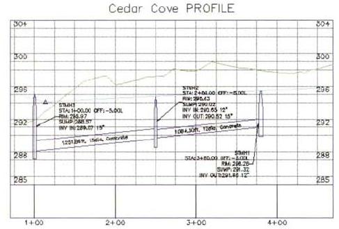
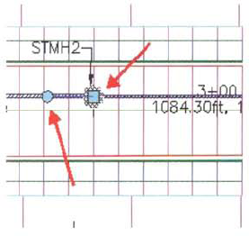
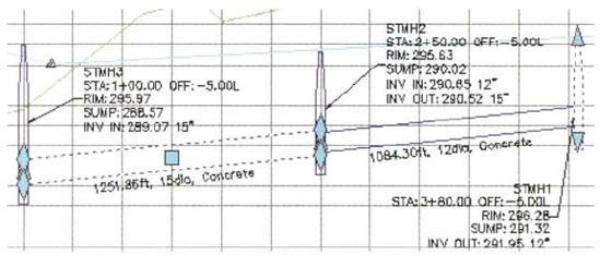
The following illustration shows a pipe network in plan, profile, and 3D views. The arrows indicate the pipe network.
After completing this lesson, you will be able to:
Describe the characteristics and function of pipe network objects.
Describe the tools that you use to create a pipe network.
Describe the three pipe network part creation modes.
List the steps for creating pipe networks.
Create a storm sewer pipe network.
A pipe network is a connected system of pipes and structures, which can be governed by rules. Its properties define the relationship between the network parts and other objects, such as surfaces and alignments.
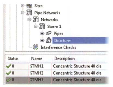
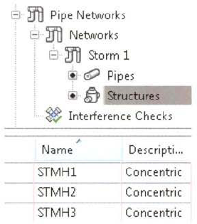
The following illustration shows the structures for a storm sewer pipe network in Prospector,
A pipe network is a system of related pipe and structure parts with properties that define relationships among the network parts, alignments, and surfaces.
A pipe network also defines the relationship between the network parts and the following objects and resources.
Option | Description |
|---|---|
Surface | If you configure your pipe network to reference a surface, the elevation data of the surface is used to determine the vertical sizing and placement of network parts. Sizing and placement of parts are calculated using the surface data and design rules for individual parts. |
Alignment | A pipe network can take its station data from an associated alignment. Label your network parts to take the station value from the associated alignment. |
Labels | You can configure your pipe network to automatically add labels of the selected type to all pipes and structures that you add to the network. You can also add labels later. |
You configure a pipe network when you create it. You can modify its configuration later using the Pipe Network Properties dialog box or the Network Layout Tools toolbar.
The following illustrations show the development of a simple pipe network.
In most cases, a pipe network design starts with another drawing object. In this example, the starting point is an alignment, as shown in the following illustration. The elevations of the pipe network parts created are determined from a surface. The surface can be an existing surface or a corridor surface representing the finished grade.
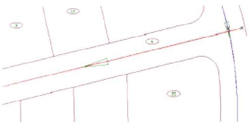
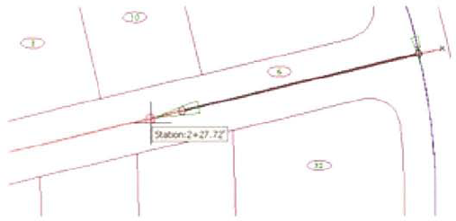
When you use another drawing object as a reference, you can use drawing tools such as Object Snap, transparent commands, and tooltips to help you select locations for your pipe network parts. In the following illustration, two structures are selected, creating a network segment with two structures connected by a pipe.
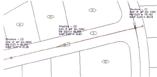
The parts you create are added to the pipe network object in the Prospector tab tree view. When you select the Pipes or Structures items, their properties are displayed in the item view. In the following illustration, the three structures added to the network are displayed.

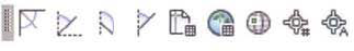
There are several tools you use to create pipe networks:
The pipe network catalog installs with the software and is external to drawings. It contains all of the available structure and pipe types.
You create a parts list and include only those parts that you would regularly use to create the pipe network. Your parts list is created based on the parts contained in the pipe network catalog, and is saved in the drawing template DWT file. Parts lists are useful for organizing pipe network parts. You create a separate parts list for storm sewers, sanitary sewers, and watermains.
Pipe and structure rules govern how the engineering details of a pipe network are calculated when the pipe network is initially created, or when you choose to apply them. The rules also affect how the pipe network parts behave when they are moved or edited. Pipe and structure rules can be associated with the individual pipe and structure parts you 3dd to the Parts List. Pipe rules and structure rules are created independent of each other and are organized into rule sets.
Pipe rules account for the following:
Cover and slope: Minimum/maximum cover and minimum/maximum slopes
Cover only: Minimum and maximum cover
Length check: Minimum and maximum pipe lengths
Pipe-to-pipe match: Pipe drop and connection location (invert, obvert, center) between adjoining pipes
Structure rules account for the following:
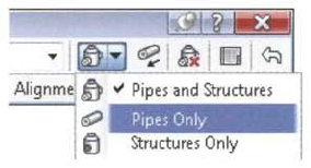
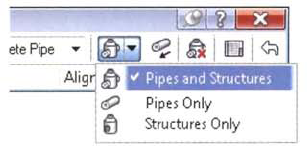
You can draft ail of the components for a utility network in a single operation using pipe network part creation modes. Depending on the requirements of your pipe network project and your design method, you select one of the following pipe network part creation modes:
Pipes and Structures
Pipes Only
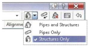
Structures Only
The pipe network part creation mode determines which network parts are added as you create a pipe network.
Option | Description |
|---|---|
Pipes and Structures | Use this mode to create network parts by selecting locations for a series of structures. Pipes that connect the structures are created automatically. This mode is useful for quickly creating a simple network such as a "cross-country" branch of a sewer or sanitary system. |
Pipes Only | Use this mode to create a network of pipes that are not connected by structures, if you have already created structures, you can use the Pipes Only mode to create connecting pipes to complete or add to the network. |
Structures Only | Use this mode to create only structures in your network. You can add pipes to the structures later. For example, you can place ail the catch basins required by your project first and add pipes later to create the configuration that is most efficient and uses the smallest quantity of materials. |
When you create pipes that connect without structures, a null structure is created. A null structure has no function except to connect two pipes. Null structures appear as simple objects in the drawing area and are listed in the Prospector tab tree view.
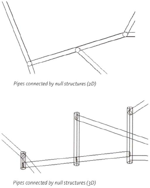
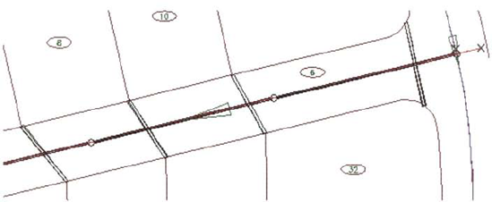
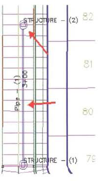
The following illustrations show examples of the Pipes Only and Structures Only pipe network part creation modes.
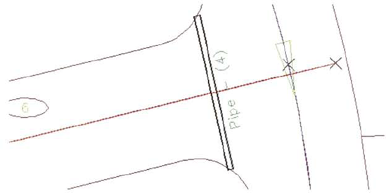
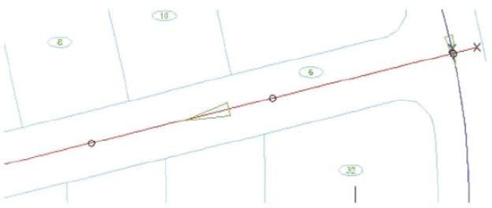
In your design project, if you need to show one or more pipes in another network that may conflict or interfere with your project, you can use the Pipes Only mode to create the required pipes without having to create connected structures. You can also use Pipes Only mode when you need to create a single, unattached pipe, such as a pipe used as a culvert under a road crossing, as shown in the following illustration.
In the following illustration, the designer drew all the required structures without pipes using Structures Only mode.
You can add pipes to the design later using Pipes Only mode to make efficient use of space and materials. The completed design is shown in the following illustration.

You can use Pipes Only mode to create models of entire systems that use only pipes. For example, you can design a water distribution network or a network of conduits that are not pipes, such as electrical lines and fiber optic casings. For a water distribution network, you can draft a design for the network, but the pipe network objects do not model the function of the network.
The following procedures show you how to create pipe networks. When you create a pipe network, you specify a default parts list that controls which parts you can create, and the surface and alignment data that is referenced as you create network parts. You then add parts to the network using a pipe network part creation mode.
The following steps describe how to create a pipe network with a default configuration.
On the ribbon, Home tab, Create Design panel, click Pipe Network > Pipe Network Creation Tools. The Create Pipe Network dialog box is displayed.
Under Network Name, enter a name for your network,
From the Network Parts list, select a parts list that includes the pipes and structures that you want to create.
From the Surface Name list, select the default surface that should determine the vertical position of network parts.
From the Alignment Name list, select the default alignment to use as a source of stationing data for your pipe network labels.
From the Structure Label Style list, select the label style to add automatically to structures as they are created.
From the Pipe Label Style list, select the label style to add automatically to pipes as they are created.
The following steps describe how to create parts for a pipe network using the Pipes and Structures pipe network part creation mode. You create parts by selecting locations for structures, which are then connected by pipes.
On the Network Layout Tools toolbar, from the Structures list, select the type of structure to create.
From the Pipes list, select the type of pipe to use to connect the structures.
Set the Toggle Upslope/Downslope button to create pipes that travel in the required direction.
From the list of pipe network part creation modes, select Pipes and Structures.
In the drawing area, click the location for the first structure.
A structure is created at the location. The vertical placement of the structure is determined from the elevation data of the referenced surface.
Click the location for a second structure.
A structure is created at the second location. A pipe is created that connects the first and second structures. The elevation and grade of the pipe are determined using the referenced surface and the design rules for the selected pipe type.
Add additional structures as required. You can change the type of structure and pipes that are created as you continue with your layout.
The following steps describe how to use the Pipes Only pipe network part creation mode.
In the drawing area, click a pipe network part
On the Network Layout Tools toolbar, from the Pipes list, select the type of pipe to use to connect the structures.
From the pipe network part creation modes list, select Pipes Only.
Click the location for the start point, then the endpoint of the pipe.
The pipe is created. The endpoint of the current pipe is the start point for the next pipe you draw.
Click the location for the endpoint of the second pipe.
The first and second pipe are joined with a null structure.
To select a start point that is disconnected from the previous pipe, on the command line, enter s.
Click the start point for the next pipe.
The following steps describe how to use the Structures Only pipe network part creation mode.
In the drawing area, click a pipe network part.
On the Network Layout Tools toolbar, from the Structures list, select the type of structure to create.
From the pipe network part creation modes list, select Structures Only,
In the drawing area, click the locations for structures, as required.
Keep the following guidelines in mind when you create pipe networks.
When you create a pipe network, use the Station and Offset transparent command on the Transparent Commands toolbar to create structures based on a fixed offset from an alignment.
When you create the drawing template for your organization, include parts lists that contain the pipe and structure parts your team would use on a regular basis.
You can automatically check for interferences between multiple pipe networks using Pipesmenu > Utilities > Create Interference Check.
To keep drawings free of annotation, create tables that show pipe network data.
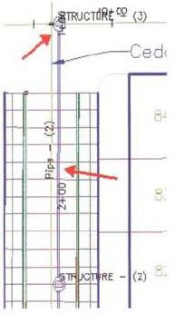
The following illustrations show the development of pipe networks using two pipe network part creation modes.
In the following illustration, structures have been created at regular intervals along the alignment without pipes using the Structures Only pipe network part creation mode.
In the next illustration, a second pipe network is created to show the placement of culverts in the project. This network is made up of single pipes created using the Pipes Only pipe network part creation mode.
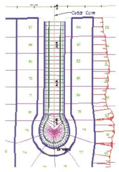
In this exercise, you use the Network Layout Tools to create a storm sewer pipe network for Cedar Cove in plan view. To assist with the creation of the pipe network, you use the Station and Offset transparent command to accurately position the structures adjacent to the alignment.
Open. ..Site Design Pipes _create_pipe_network.dwg (M_create_pipe_network.dwg).
You use the Transparent Commands toolbar to help layout the pipe network.
If the Transparent Commands toolbar is not displayed, on the command line:
Enter -toolbar. Press ENTER.
Enter transparent_commands. Press ENTER.
Press ENTER.
The Transparent Commands toolbar is now visible.
In the drawing area, click the surface.
On the contextual ribbon. Modify panel, click Surface Properties.
In the Surface Properties - FG Roads Top dialog box. Information tab, for Surface Style, click _No Display. Click OK.
Next, you create the pipe network in plan view.
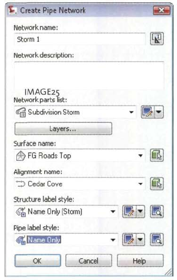
On the ribbon, Home tab, Create Design panel, click Pipe Network > Pipe Network Creation Tools.
In the Create Pipe Network dialog box:
For Network Name, enter Storm 1.
For Network Parts List, dick Subdivision Storm.
For Surface Name, click FG Roads Top. This is the surface you turned off.
For Alignment Name, click <none>.
For Structure Label Style, click Name Only (Storm).
For Pipe Label Style, click Name Only.
Click OK.
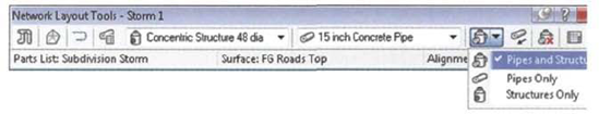
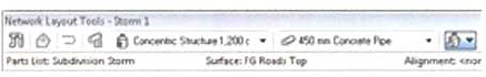
The Network Layout Tools toolbar is displayed.
Next, you select the structure type and pipe size to use. These can be changed any time when you create the network.
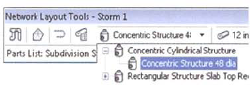
On the Network Layout Tools toolbar:
For Structure List, click Concentric Structure 48 diameter (Concentric Structure 1,200 diameter).
For Pipe List, click15 inch Concrete Pipe (300 mm Concrete Pipe).

Ensure the Upslope/Downslope toggle is set to Downslope. You draw the pipe network from upslope to down slope.
Zoom to the Cedar Cove alignment. This is the eastern cul-de-sac.
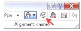
On the Network Layout Tools toolbar, click Pipes and Structures. You are prompted for the Structure Insertion Point.
Next, you use the Transparent Commands to locate the structure based on a station and offset from the Cedar Cove alignment. If you make a mistake, you can click Undo on the Network Layout Tools toolbar. If the Network Layout Tools toolbar is closed, click the pipe network (in the drawing are3, or in Prospector). Right-click, dick Edit.
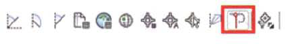
You are prompted to Specify the Structure Insertion Point. On the Transparent Commands toolbar, click Station Offset.
When prompted to Select the Alignment, select the Cedar Cove centerline alignment.
Move your mouse up and down the Cedar Cove alignment. Note the stations displayed relative to the alignment.
When prompted to Specify Station along Alignment, enter 380 (1085 m). Press ENTER.
When prompted to Specify Station Offset, enter−5(—2 m). Press ENTER.
The first structure is created.
Next, you specify the location for the next structure.
When prompted to specify Station Along Alignment, enter 250 (1050 m). Press ENTER.
When prompted to Specify Station Offset, enter −5 (—2 m). Press ENTER.
The next structure is created and connected to the first structure with a pipe.
Next, you specify the location for the last structure.
When prompted to Specify Station along Alignment, enter 100 (1000 m). Press ENTER.
When prompted to Specify Station Offset, enter −5 (—2 m). Press ENTER.
The last structure is created and a second pipe is added.
Close the Network Layout Tools toolbar.
Next, you examine the pipe network in the Toolspace window.
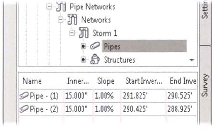
In Prospector, expand Pipe Networks, Networks, Storm 1. Click Pipes.
The pipe data displays in the Item View area. You can edit the data values for the pipe network in this area. You can right-click any column header to control which data columns to view.
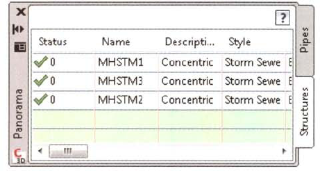
Click Structures,
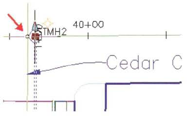
In the item View area. Name column, rename the three structures to STMH1, STMH2, and STMH3. You may need to click the Name column header to sort the list.
In the drawing, the structure labels update.

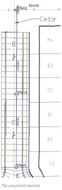
The completed drawing appears as follows:
Close the drawing. Do not save the changes.
This lesson describes how you draw pipe network parts in profile views and how you edit the pipe network.
When you draw pipe network parts in profile view, you can evaluate the engineering attributes of your design. You can also customize the appearance of labels to help you design, or meet internal or client CAD standards requirements. When you edit pipe network data, the pipe network objects and labels in plan and profile view automatically update to reflect your revisions. This makes it very easy to generate and evaluate alternatives during the planning and detailed design processes. Furthermore, when you edit the plan view location of pipe network parts, the pipe network parts in the profile view automatically update.
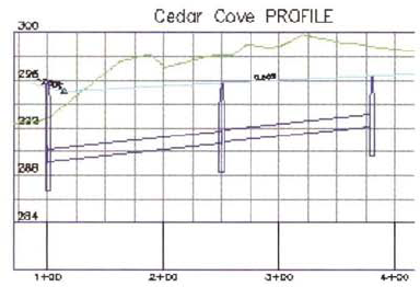
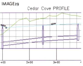
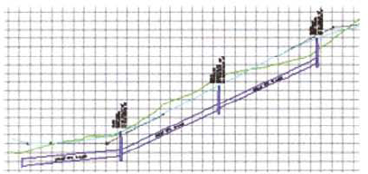
The following illustration shows a pipe network in a profile view.
After completing this lesson, you will be able to:
Describe how you draw pipe networks in plan and profile view.
Describe how you edit pipe networks graphically and in tables.
List the guidelines for drawing and editing pipe networks.
Draw a pipe network in profile view.
Edit the pipe network by moving a manhole and changing a pipe size.
When you create a pipe network, you always draw the pipe network in the plan view first. As a separate command, you can then draw the pipes in profile view.
When you create a pipe network, you always draw the pipe network in the plan view by positioning pipe network structures and connected pipes. The initial pipe invert elevations and pipe slopes are calculated using pipe and structure rules. After you draw the pipe network in the plan view, you use the Draw Parts in Profile command to draw the pipe network parts in profile view.
You can either draw individual network parts or the entire pipe network in profile view. You can draw pipe network parts in any profile view. This is useful when you want to show crossing pipes for intersecting alignments.
You can edit a pipe network either graphically or by changing the pipe data in a table.
To edit a pipe network graphically in plan view, select the pipe network part in the drawing area to activate the grips. Pipe network structures and pipes each have their own grips. When you edit a pipe network graphically, the tabular data is automatically updated.
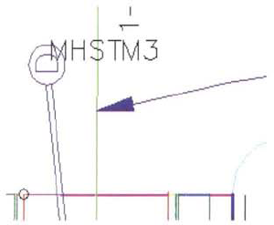
Pipe structure grips for plan view graphical editing are shown in the following illustration:
You use the circular grip to rotate the structure. This is useful for asymmetrical structures and structure styles that display text. You use the square grip to change the location of the structure.
When you move a structure, connected pipes move with the structure. Profile structures and pipes locations and associated annotation automatically updates.
Note
When you use grips to change the location of pipes in plan view, you disconnect the structure from the pipe.
There are similar grips that can be used to graphically edit structures and pipes in the profile view. These are shown in the following illustration;
You use diamond-shaped grips on pipe parts to change the invert and obvert elevation for each end of the pipe. This results in a pipe grade change.
You use the square grip on the pipe part to change the invert and obvert elevations at both ends of the pipe. This maintains the pipe grade.
You use the triangle shape grips on the structure pipes to change the rim and sump elevations.
There are several options for editing pipe network data in a table. When you edit pipe network data in a table, the graphical display of the pipe and structure objects, and associated annotation, automatically updates.
Keep the following guidelines in mind when you draw and edit pipe networks.
A single pipe style controls the display of pipe parts in plan, profile view, and section view. A single structure style controls the display of structure parts in plan, profile view, section view, and 3D views.
Pipe styles and structure styles should be developed and saved in your company/client DWT drawing template.
When you edit pipe network data in Prospector and Panorama, you can control and preconfigure the data columns to display.
To provide additional engineering details for the construction of the pipe network, draw pipes and structures in profile view.
In this exercise, you draw the pipe network in the profile view.

Open Site Design Pipesl_pipes_in_profile.dwg (M_pipes_in_profile.dwg).
First, you split the screen into two views.
On the command line, enter VPORTS. Press ENTER.
In the Viewports dialog box, click Two: Vertical. Click OK.
The screen splits into two vertical views.
In the drawing area, click in the left viewport.
In Prospector:
Expand Pipe Networks, Networks.
Right-click Storm i. Click Zoom To.
The drawing zooms to the plan view for the Storm i pipe network in the left viewport.
In the drawing area, click in the right viewport.
In Prospector:
Expand Alignments, Centerline Alignments, Cedar Cove, and Profile Views.
Right-click Cedar Cove PVi. Click Zoom To. The drawing zooms to the Cedar Cove profile view in the right viewport,
Next, you draw pipes in the profile view.
Click in the left viewport.
On the ribbon, Modify tab, Design panel, click Pipe Network.
On the Pipe Network contextual ribbon, Network Tools panel, click Draw Parts in Profile.
When prompted to Select Network(s) to Add to Profile View, select any part of the pipe network. Press ENTER.
When prompted to Select the Profile View, click in the right viewport. Click the Cedar Cove profile view.
The profile view expands and the pipes are drawn.
Close the drawing. Do not save the changes.
In this exercise, you edit the pipe network by moving a manhole and changing a pipe size. These edits result in automatic updates to the pipes in the profile view.
Open Site Design - Pipesl_edit_pipes.dwg (M_edit_pipes.dwg).
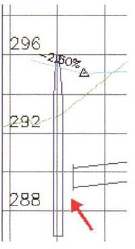
Notice the sump depths for the manholes are too deep.
Next, you modify the sump depths.
In the right viewport, select the second manhole (MHSTM2).
On the contextual ribbon tab, Modify panel, click Structure Properties.
In the Structure Properties dialog box, Part Properties tab, Under Sump Behavior, for Sump Depth, enter 0.5' (0.15 m). Click OK.
Press ESC.
Repeat steps 5 and 6 to modify the sump depths for the other two manholes.
Next, you adjust the position of the manholes in plan view.
In the left viewport, select the north pipe segment.
Select the square grip at the north end of the pipe segment.
Move the pipe to a new location.
Note that the profile view updates to reflect the new pipe location. Note that the structure location does not change and that the pipe is separated from the structure.
Click Undo. The pipe is restored to its original location and the profile view is updated.
Next, you move a manhole.
Select the north manhole. Click the square grip. Move the manhole below and to the left of the original location.
The manhole and the connected pipe move. The profile updates to reflect the change.
Click Undo.
Next, you change the pipe size for one of the pipes.
In the plan view, select the south pipe segment. Right-click the pipe segment. Click Swap Part.
In the Swap Part Size dialog box, click 12 inch Concrete Pipe (250 mm Concrete Pipe). Click OK.
The part is swapped and the profile view updates to reflect the change. Next, you review the Pipe Rules.
In Toolspace, Settings tab, expand Pipe, Pipe Rule Set. Double-click Basic.
In the Pipe Rule Set - Basic dialog box, Rules tab:
Expand Cover and Slope.
Note that the rule sets the minimum Slope to 1% and the minimum cover to 3' (3m). This rule was applied when the pipe network was created.
Click Cancel.
In Prospector:
Expand Pipe Networks, Networks, Storm 1.
Click Pipes.
In the item view area, notice that the pipes slope at 1% (You may need to scroll to the right to notice the slope columns).
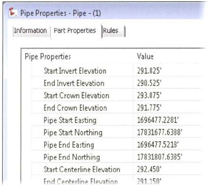
In the Item View area, right-click Pipe - (1). Click Pipe Properties.
In the Pipe Properties - Pipe - (1) dialog box, Part Properties tab, under Geometry:
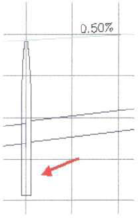
For Pipe Slope (Hold End), enter 0.5%.
Click Apply.
Click the Rules tab.
Note the minimum slope violation. In this instance, the engineer decides that the rulesviolation is acceptable. The minimum allowable pipe slope is actually 0.5%.
Click OK.
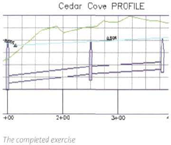
In the drawing area, the slope of the first pipe is adjusted. The final drawing appears as follows:
This lesson describes how you label pipe networks in plan and profile view.
When you label a pipe network, you display the engineering data that you need to complete and evaluate the design and to construct the pipe network. Pipe labels can be created when you create the pipe network or after you create the pipe network. Pipe labels automatically update when you make changes to the pipe network.
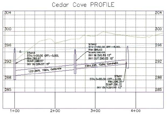
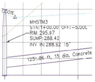
The following illustration shows a labeled pipe network.
After completing this lesson, you will be able to:
List the components of pipes that you label.
Describe how you label pipes in plan and profile view.
Label pipe networks.
You create pipe labels to convey engineering and design information.
You can label any property of a pipe network, structure, or pipe, in plan or profile view. In plan view, you typically label manhole and catch basin identification numbers. For pipes you typically label the length, description (type), and slope. In profile views, you typically label the same information, as well as the invert elevations at the structure locations and rim elevations.
You create pipe labels when you create the pipe network, or after you create the pipe network. Pipe labels automatically update when you make changes to the pipe network,
You use pipe label styles to label pipe network pipes, and you use structure label styles to label pipe network structures. Pipe and structure label styles are found in the Settings tab of Toolspace. This is shown in the following illustration:
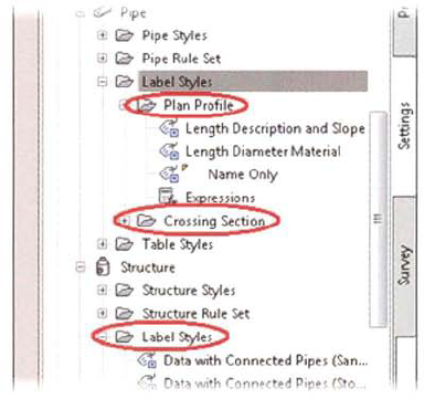
If you need to show different pipe and structure data in plan and profile, you create separate pipe and structure labels for plan and profile views. You can also create pipe label styles to label crossing pipes in the profile view.
Keep the following guidelines in mind when labeling pipes.
Modify the command settings for pipe networks to set the default pipe and structure label styles. When you do this, the correct label styles are automatically applied when you label the pipe network.
Use spanning labels to label lengths and slopes over multiple pipe segments. Spanning labels are useful when you want to label the length of an entire pipe network that spans several structures, or if you want to label a pipe network with null structures, such as a watermain network.
Pipe networks are labeled with structure label styles and pipe label styles. In this exercise, you create and apply label styles to your pipe network in both plan and profile views.
Open Site Design Pipesl_label_pipes.dwg (MJabel_pipes.dwg).
You begin by creating the labels for the pipes in plan view. You create and apply a label that shows pipe length, diameter, and material.
In Toolspace, Settings tab:
Expand Pipe, Label Styles, Plan Profile.
Right-click Name Only. Click Copy.
In the Label Style Composer dialog box, Information tab, for Name enter Length Diameter Material.
Next, you create a new text component called Pipe Data.
On the Layout tab:
Click Delete Component.
Click Create Text Component > Text.
Under General, for Name, enter Pipe Data.
Under Text, for Contents, click in the Value column. Click the ellipsis.
The Text Component Editor displays.
Widen the Text Component Editor dialog box.
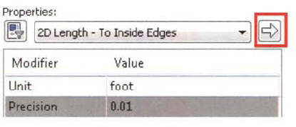
In the Text Component Editor:
In the preview area, delete "Label Text."
Under Properties, click 2D Length - To Inside Edges.
For Precision, select 0.01.
Click the right arrow to add the property.
The property, with the formatting, is added to the Text Component editor.
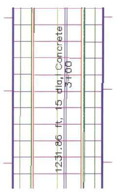
In the preview area, at the end of the existing text, enter ft, (m,). That is, enter ft followedby a comma and a space (m followed by a comma and a space).
Specify the next property:
Under Properties, click Inner Pipe Diameter.
For Precision, select 1.
Click the right arrow to add the property.
In the preview area, at the end of the existing text, enter dia, Concrete. That is, enter a space, then dia followed by a comma and a space, and then the word Concrete, then a space.
Click OK.
In the Label Style Composer dialog box, under Text, for Y Offset, enter .1 (2 mm). Press ENTER. Click OK.
Next, you remove the existing pipe labels and apply the new pipe labels to plan view.
In the left viewport:
Select a pipe label in plan view.
Right-click the pipe label. Click Select Similar.
Right-click, select Label Properties.
In AutoCAD Properties, for Pipe Label Style, click Length Diameter Material.
The pipes are labeled with the new label style.
Press ESC to end the command.
Select the south manhole label.
Click the diamond grip. Move the label away from the manhole.
Repeat the steps for the other manhole labels.
The plan view labeling is complete. Next, you label the profile views.
Click in the right viewport.
On the ribbon, Annotate tab, Label & Tables panel, click the tag on Add Labels.
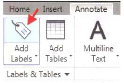
In the Add Labels dialog box:
For Feature, click Pipe Network.
For Label Type, click Entire Network Profile.
For Pipe Label Style, click Length Diameter Material.
For Structure Label Style, click Data with Connected Pipes (Storm).
Click Add.
When prompted to Select Part, select any part of the pipe network in the profile view.
The pipe network parts are labeled in the profile view. The finished drawing appears as follows:
Close the drawing. Do not save the changes.
This lesson describes how you calculate pipe sizes and invert elevations for a storm sewer p network, using the Hydraflow Storm Sewers Extension.
After completing this lesson, you will be able to:
Describe methods for designing a storm sewer network.
Design a storm sewer network.
Design a storm sewer network that includes pipe sizes and invert elevations.
This section describes storm sewer networks and the Hydraflow Storm Sewers Extension. You use the Hydraflow Storm Sewers Extension to analyze and calculate storm sewer pipe networks to ensure pipe diameters and invert elevation support designated flow rates.
Storm sewer networks are a series of connected catch basins, manholes, and pipes used to discharge storm water to an outfall location. Pipe diameters and invert elevations in a storm sewer network are calculated based on hydrologic and hydraulic analysis.
The design of a storm sewer network involves the calculation of pipe diameters and rim elevations from inputted flow data. When you create a pipe network in Civil 3D, you individually select pipe sizes from a list. Invert elevations are typically calculated based on minimum depth of cover and drop across structure rules. However, to meet the requirements of a storm sewer, network pipes must be resized and invert elevations must be recalculated using appropriate hydrologic and hydraulic analysis.
You can either manually enter flow data or use Hydraflow Storm Sewers Extension to calculate the values using traditional methods.
The Hydraflow Storm Sewers Extension:
Is a Civil 3D extension that can read pipe network geometry, pipe types, and structure types created in a Civil 3D pipe network.
Performs hydraulic analysis of both simple and complex storm sewer networks.
Can calculate pipe diameters, invert elevations, and energy grade lines for up to 250 connected storm sewer lines.
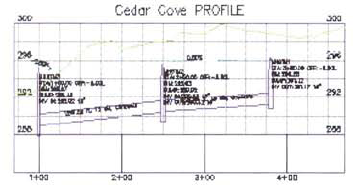
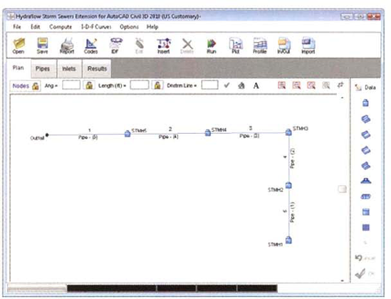
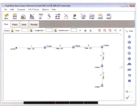
The following illustrations show a storm sewer network in Hydraftow Storm Sewers Extension in several views.
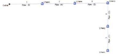
The following illustration shows the layout of a storm sewer network in plan view.
This section describes a process for laying out and designing storm sewer networks using Civil 3D and Hydraflow Storm Sewers Extension, When you design a storm sewer network, you layout the pipe network in Civil 3D, export the pipe network to Hydraflow Storm Sewer Extension to calculate flow values for the network, and import the Hydraflow Storm Sewers Extension pipe network to Civil 3D.
Laying out and designing an storm sewer network involves working in both AutoCAD® Civil 3D® and Hydraflow Storm Sewers Extension. To layout and design a storm sewer network, follow these steps:
Layout the pipe network in Civil 3D using the Pipe Network Creation Tools.
Export the pipe network to a Hydraflow Storm Sewers Extension project file.
Start Hydraflow Storm Sewers Extension, open the project file you exported from Civil 3D, and input the flow values for each pipe.
Compute the pipe sizes, invert elevations and hydraulic/energy grade lines.
Export the designed pipe network to a Hydraflow Storm Sewers Extension project file.
Import the pipe network to Civil 3D from the Hydraflow Storm Sewers Extension project file.
Update the storm sewer network with the new data.
Keep the following guidelines in mind when you create pipe networks.
Assign the Manning n (smoothness coefficient) value to pipes in the parts list in Civil 3D. When you create a pipe network from parts in the parts list, the Manning n value is transferred to Hydraflow Storm Sewers Extension. Otherwise you need to assign the Manning n value manually in Hydraflow Storm Sewers Extension.
In Hydraflow Storm Sewers extension, you must specify US Customary for imperial units or Si for metric units.
In Hydraflow Storm Sewers Extension ensure your design codes are in accordance with local standards for pipe sizing.
In this exercise, you export a basic pipe network to Hydraflow Storm Sewer Extension, compute the storm sewer network values, and import the data to Civil 3D.
Open Site Design - Pipesl_design_pipes.dwg (M_design_pipes.dwg).
The drawing contains a pipe network that was created using the AutoCAD Civil 3D Pipe Network Creation Tools. Review the pipe network in profile view and note that all pipe diameters are the same. You now export the pipe network to a Hydraflow Storm Sewers Extension project file.
In the drawing area, select any part of the storm sewer network in plan view.
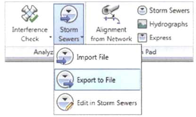
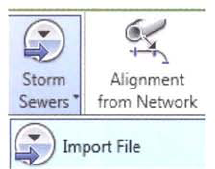
On the contextual ribbon, Analyze panel, click Storm Sewers > Export to File.
In the Export to Storm Sewers dialog box, click OK.
In the Export Storm Sewers to File dialog box:
Browse to ...Site Design Pipes,
For File Name, enter Storm 1 Layout.
Click Save.
On the contextual ribbon, Launch Pad panel, click Storm Sewers.
The Hydraflow Storm Sewers Extension launches.
If you are working in metric units, you need to change the units in the Hydraflow Extension. Click Options menu > Units > SI.
In Hydraflow Storm Sewers Extension, on the toolbar, click Open.
Note
To see the line ID labels, from the menu, click Options > Plan View > Labels > Show Line Ids.
In the Open Project dialog box;
Browse to ...Site Design - Pipes.
Click Storm 1 Layout.stm. Click Open.
Hydraflow Storm Sewers Extension displays the pipe network in plan view.
Note
Click Options menu > Plan View > Labels > Show Line Ids.
Next, you enter/confirm the Design Codes, which are the design parameters used for the calculation of pipe sizes and invert elevations.
On the toolbar, click Codes.

In the Design Codes dialog box, Pipes tab, set the following values:
Minimum Pipe Size, 12 in (75 mm)
Maximum Pipe Size, 102 in (3000 mm)
Design Velocity, 2 ft/s (.75 m/s)
Minimum Slope, 0.5%
Maximum Slope, 10%
Minimum Cover, 4ft (1.5 m)
Default n-value, 0.013
For Alignment, check Match Inverts
Matchline drop, 0.1 ft (0.03 m)
Click OK.
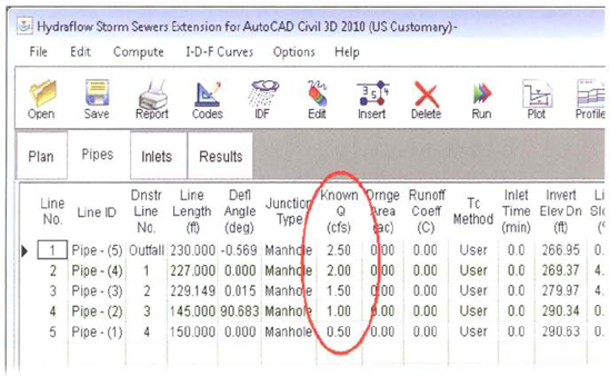
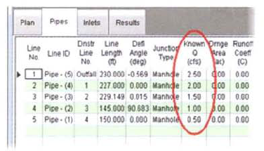
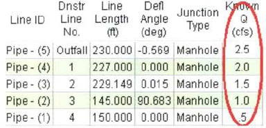
Click the Pipes tab and In the Known Q column, starting in the Pipe - (1) row, enter:
Pipe - (1): 0.5 cfs(0.015 cms).
Pipe - (2): 1.0 cfs(0.03 cms).
Pipe - (3): 1.5 cfs(0.045 cms).
Pipe - (4): 2.0 cfs(0.06 cms).
Pipe - (5): 2.5 cfs(0.075 cms).
Click the green OK check mark icon on the bottom right, to accept the values.
Next, you calculate the pipe sizes.
On the toolbar, click Run.
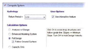
In the Compute System dialog box:
Under Calculation Options, click Full Design.
Select the Follow Ground Surface check box.
Under Starting HGLs, in the Starting HGL column, select Normal.

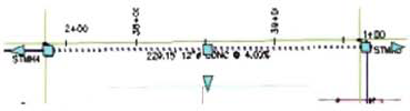
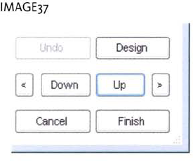
In the Storm Sewers Design dialog box, note that Pipe - (5) is displayed in a profileReview the data for Pipe - (5).
Click Up to review the data for the remaining pipes in the run.
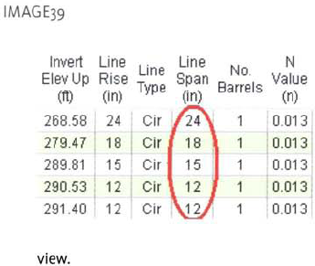
On the Pipes tab, notice the updated pipe diameters in the Line Span column. The pipes are no longer all 12" diameter and have been resized based on the inputted flow values.
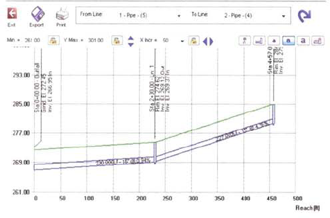
On the toolbar, click Profile.
In the Storm Sewer Profile dialog box, for To Line, select 5 - Pipe (1). Click Update.
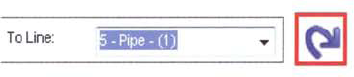
Hydraflow Storm Sewers Extension displays the entire pipe run in a profile view.
Close the Storm Sewer Profile dialog box.
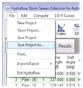
Finally, you export design data to a project file, and import to Civil 3D.
Click File menu > Save Project As.
In the Save Project As dialog box:
Browse to ...Site Design - Pipes.
For File name, enter Storm 1 Design. Click Save,
Click OK.
Close Hydraflow Storm Sewers Extension.
Click OK.
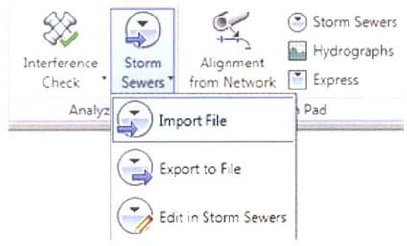
Next, you import the data to Civil 3D.
Click in the AutoCAD Civil 3D window.
On the contextual ribbon. Analyze panel, click Storm Sewers > Import File.
In the Import Storm Sewers File dialog box:
Browse to ...Site Design - Pipes.
Click Storm 1 Design.stm.
Click Open.
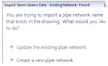
In the Update Storm Sewers Data dialog box, click Update the Existing Pipe Network.
Close Panorama.
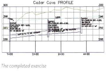
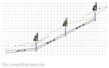
The pipe network in Civil 3D is updated with the calculated invert elevations and pipe diameters from Hydraflow Storm Sewers Extension. The pipes in plan and profile view are displayed and annotated with the design data.
The completed exercise drawing appears as follows:
Close the drawing. Do not save the changes.