
This chapter guides you through the process of creating alignments for transportation design projects. Unlike alignments for site design and subdivision projects, alignments for transportation projects are often created using the layout tools available on the Alignment Layout Tools toolbar. Transportation alignments are usually more complicated and include spiral and complex curve geometry. Also, design speeds and design criteria are applied to ensure that curve geometry meets the minimum standards requirements, and to apply super elevation to the alignment.
In the Designing Criteria-Based Alignments lesson, you create an alignment object using tools on the Alignment Layout Tools toolbar, and you modify the properties of the alignment to assign a design speed and design criteria. This helps you identify the substandard curves in the alignment geometry, which are then edited to meet the minimum design standard. This lesson also describes the difference between fixed, floating, and free alignments. In the Applying Superelevation lesson, you apply superelevation to the alignment from data residing in a design criteria file. In the Creating Offset Alignments lesson you learn how to create offset and widening alignments that are geometrically tied and related to a centerline alignment.
In this lesson you create a criteria-based alignment and edit it using the layout tools. When engineers plan and design transportation facilities for both new construction and road reconstruction projects, they must create and then edit the alignments used to control the design of the road. You create tangent, curve, and spiral alignment components with layout tools, and you can edit alignments both graphically and in a table.
You interact with the alignment geometry and edit data graphically or directly in a table. When you edit alignment data in a table, the graphical display of the geometry and associated annotation is automatically updated. When you edit alignment data graphically, curves maintain tangency to the lines. When you edit alignment geometry, surface profile data also automatically updates.
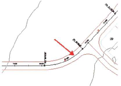
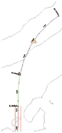
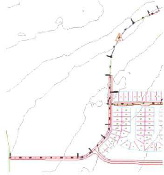
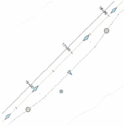
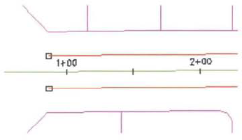
The following illustration shows an alignment object.
After completing this lesson, you will be able to:
Describe horizontal alignments.
Describe the options for editing alignments.
Explain criteria-based design.
Create and edit a horizontal alignment.
Creating and defining the alignment is one of the first steps in a transportation design project. The alignment controls the horizontal location of a transportation corridor model. When you create an alignment, you can assign design criteria to ensure that you meet the minimum curvature and superelevation requirements for the project.
An alignment is a series of coordinates, lines, curves, or spirals used to represent linear features, such as the centerline of a road, edges of pavement, sidewalks, and rights-of-way.
Alignments are created and displayed with subentities. The alignment components are lines, curves, spirals, arrows, line extensions, and curve extensions. Alignment lines, curves, and spirals can be either fixed, floating, or free. Fixed, floating, and free entities are summarized in the following table.
Term | Description |
|---|---|
Fixed Entities | Alignment lines, curves, and spirals can be fixed entities. Fixed entities have a fixed position and are not necessarily tangent to another entity for the definition of its geometry. |
Floating Entities | Alignment lines, curves, and spirals can be floating entities. When a floating entity is created, it is tangent to one other alignment entity for the definition of its geometry. |
Free Entities | Alignment lines, curves, and spirals can be free entities. When a free entity is created, it is tangent to two other alignment entities for the definition of its geometry. |
You can edit an alignment by grip editing or by changing the layout parameters in a table shown in specialized windows.
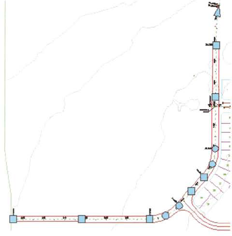
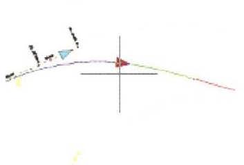
When you select an alignment, graphical editing grips are displayed. The square grips are used to edit tangents, the circular grips are used to edit curves, and the triangle grips are used to edit the PI location. As you make changes, an alignment retains its tangency rules at curves, and all alignment labels are dynamically updated. The shapes of the grips displayed depend on whether or not the alignment entities are fixed, floating, or free. You can edit the location of tangents and resize curves and spirals.
Grip Type | Description |
|---|---|
Circular grip | Changes the parameter of curve. You can change the radius by moving a center point, pass-through point, or the tangency point of an attached curve. This grip is used only on curves and circles and always affects the radius of the curve. |
Square grip | Moves an unconstrained pass-through point on a line, a curve, or a center point of a circle. On a curve or a circle, moving this grip does not affect the radius of the entity that the grip belongs to. However, it may affect the radius of another attached entity. |
Triangular grip | Changes where two tangent points meet. This grip is always oriented with the top point up, toward the Y axis of the world coordinate system. |
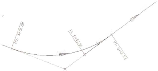
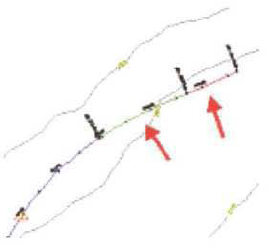
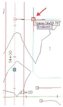
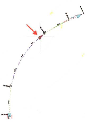
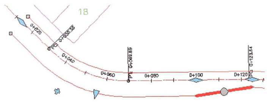
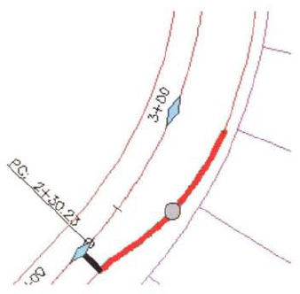
The following illustration shows that when you select an alignment, blue editing grips appear at the curve ends, midpoints, and points of intersection (Pls). By using these grips, you can move alignment features directly and reshape a line or curve using visual cues. Use this method of editing when precision is not important.
When you edit alignment data in a table, you modify values to change tangent bearings, curve radii, and spiral geometry parameters. The alignment object in the drawing and associated annotation automatically updates. The alignment segments are numbered according to both their position in the alignment and their order of creation. Each row of the table shows design data about a specific alignment entity.
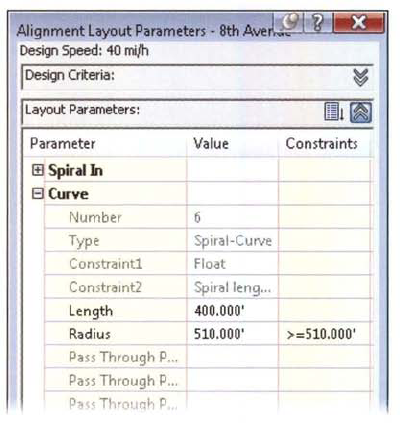
The design data for an entity that you select in the Alignment Entities window is displayed in the Alignment Layout Parameters window. This simplifies review and edit tasks.
For precise alignment editing, such as when your design calculations and reference tables provide numeric values for minimum curve radius, length, or spiral A values, you use the Alignment Layout Parameters window.
Alignments used to define transportation-related entities may be complicated and include spiral and complex curve geometry. The criteria-based design feature provides the ability to verify that your alignment design meets the minimum standards required by your local agency. Options to customize and specify a design criteria file ensures that curve geometry based on design speeds and criteria for your locality are met and the appropriate superelevation is applied to the alignment.
Criteria-based design is an option available to the engineer when creating a new alignment or editing an existing one. It enables the engineer to verify that a design meets the local agency's design standards. When this option is used, the alignment is checked against the minimum values specified in a design criteria file. This design criteria file is XML based. The file contains all the local agency's minimum design values for such parameters as the minimum curve radius, superelevation attainment method, and the spiral transition length for a wide range of design speeds.
If this option is used when laying out a new alignment, the appropriate minimum values are displayed on the command line for acceptance. If you apply these design criteria to an existing alignment, then the entire alignment is checked against the design values. In either case, whether the design criteria is applied during alignment layout or applied to an existing alignment after the fact, any segment of the alignment that does not meet the minimum values specified in the design file is flagged with a warning symbol. This warning symbol provides a tooltip with information about the standard that was violated, and what the standard value should be.
The following table provides a description of the terms and options available to the engineer when applying Criteria-based design to alignments. Only the horizontal component of an alignment is being described here. The vertical component is discussed in a later lesson.
Term | Definition |
|---|---|
Criteria-Based Design | This option enables the use of criteria-based design to be applied to the current alignment |
This option enables you to specify the location of the XML file that contains the all of the local agency's design standards controlling the minimum horizontal and vertical design parameters. | |
Default Criteria | This list displays the major design categories and their values that will be used in the layout process. These categories are contained in the design criteria file and include the minimum radius table, the transition length table, and the superelevation attainment method for horizontal layout, as well as the minimum K table used in vertical layout. |
This option allows for the use of Design checks against the current alignment. A Design Check is a user-defined expression used to verify that an entity meets the minimum design standards that were established for the alignment or profile object. Design checks may be defined for different entity types, such as lines, curves, and spirals. A design check must be saved in a design check set to be applied to an alignment or profile. |
For more information use Help files,
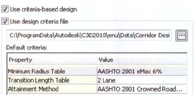
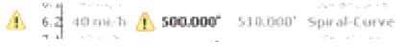
The design criteria file and some criteria values are shown in the following illustration.
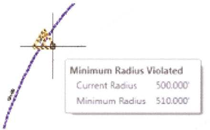
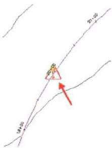
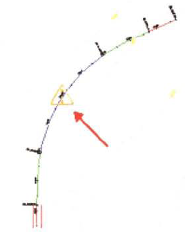
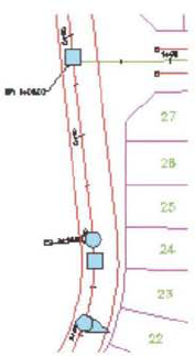
If the design parameters for a subentity violate the minimum values established in the design criteria file, a warning marker displays on the subentity in the drawing window. The display of the warning symbol is controlled by the object's style (profile or alignment).
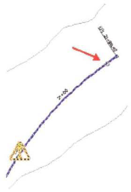
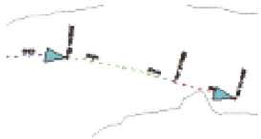
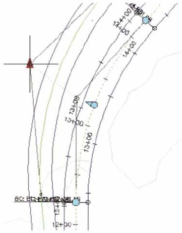
The following illustration shows a Design Check Marker warning that shows that minimum radius violation has occurred, and that the radius should be a minimum of 6om for the given design speed.
In this exercise, you create an alignment using the Alignment Layout Tools toolbar. You then edit the alignment using two different methods.
First, you create an alignment.
Open Transportation - Alignmentsl_alignment_bylayout.dwg (M_alignment_by_lay out.dwg).
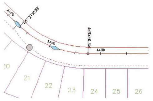
In the drawing area, notice the collector road alignment along the west side of the proposed subdivision. The south part of the centerline alignment has been designed and is represented with AutoCAD® tangents and arcs.
On the ribbon, Home tab, Create Design panel, click Alignment > Alignment Creation Tools.
In the Create Alignment - Layout dialog box, General tab:
For Name, enter 8th Avenue.
For Type, select Centerline.
For Site, select <None>.
For Alignment Style, select Layout.
For Alignment Label Set, select All Labels.
Click the Design Criteria tab and:
For Starting Design Speed, enter 4omi/h (7okm/h).
Check Use Design Criteria File check box.
For Minimum Radius Table, select AASHTO 2001 eMax 6%.
Clear Use Design Check Set checkbox.
Click OK.
On the Alignment Layout Tools -8th Avenue toolbar, click Convert AutoCAD Line and Arc.
When prompted to Select Line, Arc to Convert, from left to right, select the five centerline alignment entities (three tangents and two arcs in the order: tangent, arc, tangent, arc, and tangent) that form the south part of 8th Avenue. Press ENTER.
This creates an alignment object from the selected entities. The original line and arc entities are still in the drawing and unnecessarily duplicate the alignment object.
Next, you remove the original line and arc entities.
In the drawing area:
Select the 8th Avenue alignment object that you created in the previous step.
Right-click, click Display Order > Send to Back.
Select the three tangents and two arcs you originally selected to create the slignment. Press DELETE.
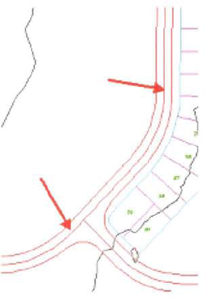
Next, you construct the remainder of the alignment, which begins with a floating curve attached to the north end of the alignment.
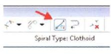
On the Alignment Layout Tools - 8th Avenue toolbar, click Floating Curve with Spiral (from Entity End, Radius, Length).
When prompted to Select Entity to Attach To, select a point on the tangent near the north end of the alignment.

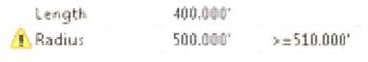
Notice that the default radius is 510' (195 m). This is the minimum value for the assigned design speed.
When prompted to:
Specify Radius, enter 500(185 m). Press ENTER.
Specify Spiral in Length, enter 175 (50 m). Press ENTER.
Specify Curve in Direction, press ENTER to accept Clockwise.
Specify Length, enter 400(170 m), Press ENTER twice.
The entrance spiral and the curve of the new portion of the alignment are complete.
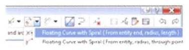
Next, you create the exit spiral and tangent,
On the Alignment Layout Tools toolbar, click Floating Line with Spiral (From Curve End, Length).
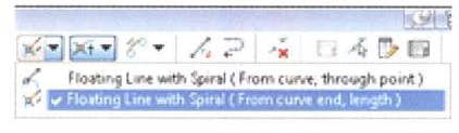
When prompted to Select Entity to Attach To, select the last curve near the endpoint of the alignment.
When prompted to:
Specify Spiral in Length, enter 175(5o m). Press ENTER.
Specify Line Length, enter 100 (30 m). Press ENTER twice.
This creates the existing spiral and tangent and applies stationing to the remainder of the alignment.
Next, you change the starting station for the design speed. The assigned design speed is only applicable for the new section of the alignment to the north of the subdivision.
In the drawing select the alignment. Right-dick, click Alignment Properties.
In the Alignment Properties - 8th Avenue dialog box, Design Criteria tab:
Click in the Start Station cell. Click the Select Station icon.
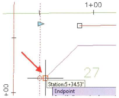
In the drawing area, use the endpoint OSNAP and snap to the northwest corner of Parcel number 1.
Click OK.
This creates a design speed label in the drawing area. Notice the warning symbol alignment component on the curve.
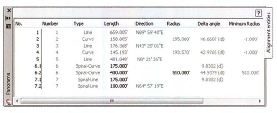
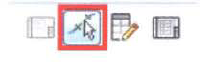
On the Alignment Layout Tools toolbar, click Alignment Grid View.
This displays the alignment data in the Panorama window. Notice the minimum radius design criteria violation. You may need to adjust the column display to show the data.
Close the Alignment Layout Tools -8th Avenue toolbar.
Close the drawing. Do not save changes.
Next, you edit the alignment.
Open Transportation - Alignmentsl_edit_alignment.dwg (M_edit_alignment.dwg).
You begin by editing the alignment data in a table to correct violations to the assigned design criteria. Notice the design criteria warning symbol component at the north end of the alignment.
The path for the design criteria file referenced by the alignment in this drawing is based on Windows Vista. If you are using Windows XP, proceed to step 2. If you are using Windows Vista, proceed to step 3.
Set the path for the design criteria file.
In the drawing area, select the alignment.
Right-click, click Alignment Properties,
In the Alignment Properties dialog box, click the Design Criteria tab.
Under Use Design Criteria File, click the ellipsis.
In the Select Design Speed Table dialog box, browse to ...AutodeskC3D 2oioenuDataCorridor Design Stondardsimperial (Metric).
Select _Autodesk Civil 3D Imperial (Metric) Roadway Design Standards.xm1.
Click Open.
For Minimum Radius Table, click AASHTO 2001 eMax 6%.
Click OK. Press ESC.
In the drawing area, select the 8th Avenue alignment. On the contextual ribbon, click Geometry Editor.
On the Alignment Layout Tools - 8th Avenue toolbar, click Pick Sub-entity. In the drawing area select the curve with the design criteria warning symbol.
In the Alignment Layout Parameters - 8th Avenue dialog box, notice the design criteria violation for radius. Close the Alignment Layout Parameters - 8th Avenue window.
On the Alignment Layout Tools toolbar, click Alignment Grid View,
In Panorama:
Notice the design criteria violation for the curve radius.
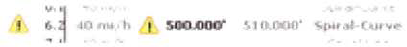
For No. 6.2, click in the Radius column.
Change the radius to 510' (195 m). Press ENTER.
The design criteria violation warning symbol is removed in the table and in the drawing, and the alignment geometry is updated.
Close the Alignment Layout Tools toolbar.
Next, you edit the alignment graphically.
In the drawing area select the 8th Avenue alignment. Zoom to the north end of the alignment. Click the grip on the endpoint of the curve.
Move the grip to the right.
Select a location. Click to lengthen the curve.
The geometry and stationing for the alignment are updated. The existing spiral and tangent are floating entities and therefore maintain tangency to the curve.
Close the drawing. Do not save changes.
This lesson describes how you apply superelevation to alignments. Superelevation is the purposeful canting of road or railway cross section within spiral and curve alignment components. The intent is to counteract centrifugal forces to allow for higher design speeds and safer passage through alignment spirals and curves.
To calculate superelevation values for an alignment, you modify alignment properties to assign a design speed. The superelevation values are referenced from a rate table in a design criteria file. Each curve is a superelevation region, and for each superelevation region you can assign independent superelevation properties. You can also apply the superelevation properties of one superelevation region to the other superelevation regions in the alignment,
When you use alignment design criteria and superelevation, you associate standard imperial and metric superelevation tables with the alignment to calculate minimum curve radii and superelevation critical values for assigned design speeds. The superelevation values assigned to an alignment are referenced when you create the corridor model for the transportation facility.

After completing this lesson, you will be able to;
Describe criteria-based design and superelevation.
List the guidelines for calculating superelevation.
Calculate and apply superelevation to an horizontal alignment.
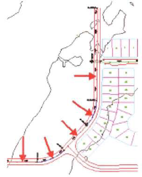
Superelevation is calculated for an alignment when you assign a design speed, a design criteria file, a rate table, and a transition length table. You can assign different design speeds at different locations along the alignment.
Design criteria files are available for both imperial and metric units. The rate table indicates the superelevation rate, or the maximum section cross fall. The transition length table is used to assess the length it takes to achieve full superelevation, and the locations of the critical superelevation points.
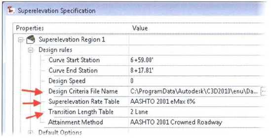
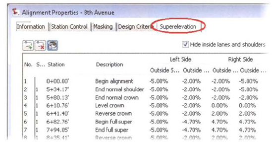
The following illustration shows the superelevation specifications for a superelevation region on an alignment. Notice the design criteria file, superelevation rate table, and the transition length table assignment.
Superelevation is the purposeful banking of a roadway to provide for smooth and safe travel around a curved section of road at the design speed. The purpose of superelevation is to counteract the centripetal and frictional forces experienced by a vehicle as it moves along this curved path.
Superelevation is defined and applied in the Alignment Properties dialog box, shown below. To calculate superelevation you need to specify the design speed, the minimum radius table, and the superelevation attainment method. The following illustration shows the calculated superelevation critical points for an alignment.
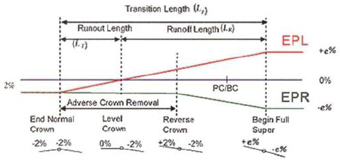
The following illustration shows how superelevation is attained for a clockwise-direction curve on a crowned roadway. To achieve the superelevation, the left edge of pavement rises and the right edge of pavement drops.
Superelevation is defined and applied in the Alignment Properties dialog box. To calculate superelevation you need to specify the design speed, the minimum radius table, and the superelevation attainment method.
Keep the following guidelines in mind when calculating superelevation for an alignment.
When assigning superelevation to an alignment, be sure to leave enough tangent between reverse curves to adequately generate sufficient runout and runoff.
After you apply superelevation to an alignment, you can modify the location of critical superelevation points when you modify the alignment properties.
If the consecutive curves on an alignment are close together, there may not be sufficient tangent length to transition the superelevation out of one curve and into the next curve. In these instances you can manually adjust the superelevation by adding, removing, and changing the location of superelevation critical points.
In this exercise, you calculate and apply superelevation to an alignment.
Open (Transportation Atignmentsl_superelevation.dwg (M_superelevation.dwg).
The path for the design criteria file referenced by the alignment in this drawing is based on using Windows Vista. If you are not using Windows Vista, then proceed to the next step. Otherwise skip the next step and continue to step 3.
Set the path for the design criteria file.
In the drawing area, select the alignment.
On the contextual ribbon, click Alignment Properties.
In the Alignment Properties dialog box, click the Design Criteria tab.
Under Use Design Criteria File, click the ellipsis.
In the Select Design Speed Table dialog box, browse to ...AutodeskC3D 2010enuDataCorridor Design Standardsdsimperial (Metric).
Select _Autodesk Civil 3D Imperial (Metric) Roadway Design Standards, xml.
Click Open.
For Minimum Radius Table, click AASHTO 2001 eMax 6%.
Click OK.
In the drawing area, select the 8th Avenue alignment. Right-click, click Alignment Properties.
On the Alignment Properties - 8th Avenue dialog box, Design Criteria tab, notice the following:
Design Speed is 40 mi/h (70 km/h).
Use Criteria-Based Design is selected.
Use Design Criteria File is selected.
Minimum Radius Table is AASHTO 2001 eMax 6%.
Click the Superelevation tab and Click Set Superelevation Properties to calculate the superelevation.
In the Superelevation Specification dialog box:
Notice the three superelevation regions. Each superelevation region represents a curve in the alignment.
Collapse Superelevation Region 1 and Superelevation Region 2.
For Superelevation Region 3, Design Rules, Superelevation Rate Table, select AASHTO 2001 eMax 8%.
Click OK.
The superelevation for the three curves is calculated. For this exercise, you concentrate on the third curve.
Next, you delete the superelevation data for the first two curves.
On the Superelevation tab:
Scroll to the top of the superelevation data.
Select the first row.
Scroll down to the last entry for Superelevation Region 2.
SHIFT+select line 21. All entries for superelevation regions 1 and 2 (curves 1 and 2) are highlighted.
Click Delete Transition Station.
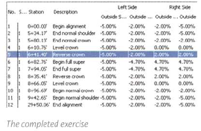
Only the superelevation entries for the third curve remain.
Click any cell.
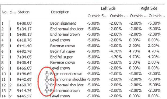
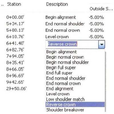
Notice that you can modify superelevation stations, descriptions, and values in this table. You can also add other locations for superelevation.
Click OK.
Close the drawing. Do not save the changes.
This lesson describes how you create an offset alignment to model alignment offset features.
Offset alignments are directly related to the centerline alignment. When you change the geometry of the centerline alignment, the geometry of the offset alignment automatically recalculates based on the offset parameters.
After completing this lesson, you will be able to:
Describe offset alignments.
Describe the process for creating offset alignments.
Create offset alignments and widenings.
You use offset alignments to model alignment offset features such as pavement edges, gutter lines and sidewalks.
An offset alignment is a dynamic alignment created at an offset distance from another alignment, such as a road edge offset from a centerline alignment. Offset alignments run parallel to the centerline alignment and are defined to model features such as pavement edges, gutter lines and sidewalks.
The geometry of offset alignments are based on the geometry of the centerline alignments. When you edit the geometry of the centerline alignment, the offset alignment will automatically update to follow the geometry of the centerline alignment, at a specified offset value.
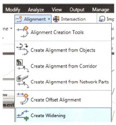
Widenings expand the width of a roadway for a specified length to accommodate a feature such as a turn lane or bus bay. The widening usually includes a transition region at one or both ends. The Create Widening command simplifies the creation of roadway features such as turn lanes, acceleration lanes, deceleration lanes, and bus bays.
When you create a widening, you can either create a new offset alignment or modify an existing offset alignment.
If the alignment is an offset, it is widened by the value you specified and the widening parameters are added to the properties. If you add a widening to an alignment that is not an offset, the command creates a new dynamic offset alignment. You can edit the widening by using grips or modifying the values in a table.
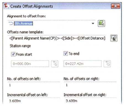
To create an offset alignment you, select a centerline alignment (alignment to offset from), specify the starting and ending station of the offset alignment relative to the centerline alignment, and specify the offset distances on the left and right sides. To create multiple offsets, specify how many you want to create for each side.
To create an offset alignment, you select: the parent alignment, a station range, and the distance the offset should maintain from the parent alignment. To create multiple offsets, specify how many offsets you want to create from each side.
The following steps show how you create an offset alignment.
Launch Create Offset Alignment command. Select alignment location.
Configure offset alignment parameters.
Add a widening as required. Enter start station. Enter end station. Enter widening width.
Edit widening and transition parameters.

For each widening, specify the entry transition length, widening length, and exit transition length.
Specify default transition lengths in the command settings for the AddWidening command.
Curb return alignments in intersections can be edited to add widening at one or both ends. This type of widening forms a turn lane at the entry to a curb return or a merge lane at the exit from a curb return.
Offset and widening geometry parameters can be modified after they have been created.
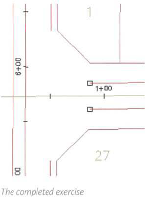
In this exercise, you create an offset alignment and a widening on an alignment. You atso hide the display of an alignment by applying an alignment mask.
Open Site Design - AHgnmentsl_offsets_widening,dwg (M_offsets_widening,dwg).
First, you create offset alignments for the 8th Avenue alignment.
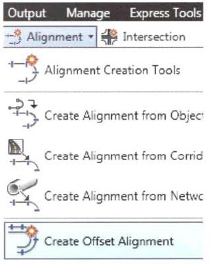
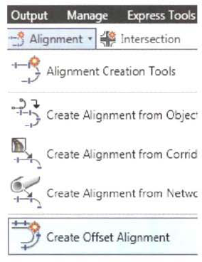
On the ribbon, Home tab, Create Design panel, click Alignment > Create Offset Alignment.
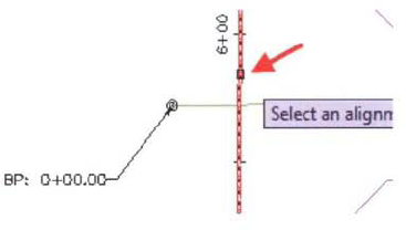
When prompted to Select an Alignment, in the drawing area, select the 8th Avenue alignment.
This is the south to north alignment on the west side of the site.
In the Create Offset Alignments dialog box:
For Incremental Offset on Left, enter 12' (3.6 m).
For Incremental Offset on Right, enter 12' (3.6 m).
For Alignment Style, select Proposed Edge of Pavement.
For Alignment Label Set, select_No Labels.
Click OK.
Two offset alignments are created.
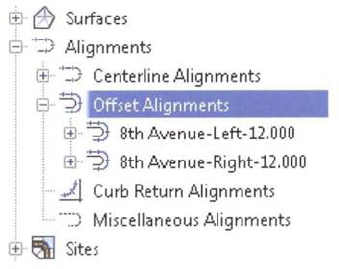
In Prospector, expand Alignments, Offset Alignments. Note the two new offset alignments.
Next, you create offset alignments for Orchard Road, the east to west alignment inside the subdivision.
On the ribbon, Home tab, Create Design panel, click Alignment > Create Offset Alignment.
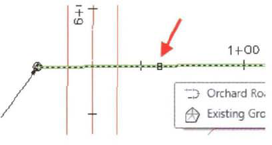
When prompted to Select an Alignment, in the drawing area, select Orchard Road.
In the Create Offset Alignments dialog box:
Clear the From Start check box.
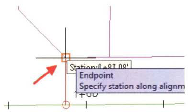
Click the icon to the right of the start station cell, to pick the starting station in the drawing.
When prompted to Specify Station Alignment, snap to the south endpoint of the property line chamfer in parcel number 1.
In the Create Offset Alignments dialog box:
For Incremental Offset on Left, enter 12' (3.6 m).
For Incremental Offset on Right, enter 12' (3.6 m).
For Alignment Style, select Proposed Edge of Pavement.
For Alignment Label Set, select _No Labels.
Click OK.
Offset alignments are created for Orchard Road.
Next, you model a deceleration and acceleration lane for 8th Avenue at the 8th Avenue and Orchard Road intersection. You add a widening to the right offset alignment.
In the drawing area, select the right offset alignment for 8th Avenue.
On the contextual ribbon. Modify panel, click Add Widening.
When prompted to Create Widening Portion as a New Alignment, click No.
When prompted to Select Start Station, enter 300(100). Press ENTER.
When prompted to Select End Station, snap to the north endpoint of the 8th Avenue alignment.
When prompted to Enter Widening Offset, enter 24' (7.2 m).
The Offset Alignment Parameters patette is displayed.
In the Offset Alignment Parameters palette:
For Transition Length, enter 85' (25 m)
Under Transition Parameters at Entry, for Transition Type at Entry, select Curve Reverse - Curve.
Close the palette.
The offset alignment with an entry transition is modeled in the drawing area. The offset alignment will react when you change the geometry of the 8th Avenue Centerline alignment.
In the drawing area, select the 8th Avenue centerline alignment to show the editing grips.
Click the blue square grip on the north end of the north tangent.
Click a location to the left to relocate the tangent.
The offset alignment with widening changes to follow the 8th Avenue Centerline alignment.
On the Quick Access toolbar, click Undo to restore the 8th Avenue to its original location.
Next, you hide a portion of the offset alignment by masking the alignment.
In the drawing area, select the 8th Avenue right offset alignment. Right-click, click Alignment Properties.
In the Alignment Properties dialog box, click the Masking tab. Click Add Masking Region.
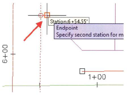
When prompted to Specify First Station for Masking Region, select the south chamfer end point for the parcel southeast of the 8th Avenue and Orchard Road intersection.
When prompted to Specify Second Station for Masking Region, select the north chamfer endpoint for the parcel northeast of the 8th Avenue and Orchard Road intersection.
In the Alignment Properties dialog box, click OK.
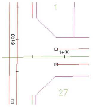
The 8th Avenue right offset alignment is masked in the vicinity of the intersection.
Close the drawing. Do not save the changes.