
In this section, we will build our first Hello World!!! Vulkan application. The application is built using the pseudocode program model, which offers the following benefits:
- Learning through a step-by-step process how to build a Vulkan application.
- Vulkan coding is lengthy and beginners might get lost in the detail. The pseudocode highlights only the necessary details that are easy to understand.
- A compact form of the program, which is easier for first-time users to memorize.
- Each pseudocode uses the real Vulkan API and explains the control flow.
- By the end of this chapter, if you are a complete beginner, you'll able to understand Vulkan programming and all the necessary clues to build applications from scratch. In addition, you will learn about the high-level concepts of Vulkan APIs with their responsibilities and functionalities.
- For a detailed understanding of the API, use the Vulkan specification available with the LunarG SDK. Or refer to https://www.khronos.org/registry/vulkan/specs/1.0/apispec.html.
Tip
Given the scope of this chapter, it is not possible to provide a line-by-line description of each data structure field and API argument. The pseudocode is only limited to providing a high-level definition, an overview and related functionalities in a maximum of one to two lines for most of the important data structures or APIs. All the Vulkan APIs and related data structures will be thoroughly covered as we proceed through the upcoming chapters in this book.
Vulkan initialization includes the initialization of validation layer properties and instance object (VkInstance) creation. Once the instance is created, check the available physical devices (VkPhysicalDevice) on the existing system. Choose the intended physical device and create a corresponding logical device (VkDevice) with the help of the instance object. In Vulkan programming, logical devices are used in most of the APIs that represent a logical representation of the physical device.

Vulkan provides debugging capabilities by means of error and validation layers. There are two types of extension:
- Instance-specific: This provides global-level extensions
- Device-specific: This provides physical-device-specific extensions

At the beginning, the system is enumerated for global layers and device-specific extensions; these are exposed by the Vulkan driver. The global layers and extensions can be injected into the instance object to be enabled at the global level. However, enabling the extensions only at the device level will enable them only at that specific device.
The initialization is responsible for creating instance and device objects. In addition, global layers/extensions are queried and enabled at either the global or instance level. Similarly, the extensions are enabled on the specific device. The following is the pseudocode for the initialization process:
- Enumerating Instance Layer properties: Vulkan first communicates with the loader and locates the driver. The driver exposes a number of extensions and layers, which may vary with each new installation or from one GPU vendor to another.
vkEnumerateInstanceLayerPropertiesretrieves the number of layers and their properties. Each layer may contain multiple extensions that can be queried usingvkEnumerateInstanceExtensionProperties:/*** 1. Enumerate Instance Layer properties ***/ // Get number of instance layers uint32_t instanceLayerCount; // Use second parameter as NULL to return the layer count vkEnumerateInstanceLayerProperties(&instanceLayerCount, NULL); VkLayerProperties *layerProperty = NULL; vkEnumerateInstanceLayerProperties(&instanceLayerCount, layerProperty); // Get the extensions for each available instance layer foreach layerProperty{ VkExtensionProperties *instanceExtensions; res = vkEnumerateInstanceExtensionProperties(layer_name, &instanceExtensionCount, instanceExtensions); }
- Instance creation: The instance object (
VkInstance) is created using thevkCreateInstance()API with parameters specifying the name of the layer and extensions that are to be enabled for validation or debugging purposes. These names are specified in theVkInstanceCreateInfostructure:/*** 2. Instance Creation ***/ // Vulkan instance object VkInstance instance; VkInstanceCreateInfo instanceInfo = {}; // Specify layer names that needs to be enabled on instance. instanceInfo.ppEnabledLayerNames = { "VK_LAYER_LUNARG_standard_validation", "VK_LAYER_LUNARG_object_tracker" }; // Specify extensions that needs to be enabled on instance. instanceInfo.ppEnabledExtensionNames = { VK_KHR_SURFACE_EXTENSION_NAME, VK_KHR_WIN32_SURFACE_EXTENSION_NAME}; // Create the Instance object vkCreateInstance(&instanceInfo, NULL, &instance);
- Device creation: Enumerate the number of physical devices or GPUs on the existing system and get the
vkEnumeratePhysicalDevices()API:/*** 3. Enumerate physical devices ***/ VkPhysicalDevice gpu; // Physical device uint32_t gpuCount; // Pysical device count vector<VkPhysicalDevice>gpuList; // List of physical devices // Get number of GPU count vkEnumeratePhysicalDevices(instance, &gpuCount, NULL); // Get GPU information vkEnumeratePhysicalDevices(instance, &gpuCount, gpuList);
For each physical device, enumerate device-specific extensions in the same way we did during instance creation.
With the physical device list in hand, query the following information:
- Queue and queue types: Query the available physical device queues and queue properties using the
vkGetPhysicalDeviceQueueFamilyPropertiesAPI. Among the queried queues, search for the graphics-capable queue and store its queue family index in the application for later use. The graphics queue is chosen because we are only interested in drawing operations. - Memory information: The
vkGetPhysicalDeviceMemoryProperties()API retrieves the available memory types on the intended physical device. - Physical device properties: Optionally, you can store physical device properties to retrieve some specific information while programming. This can be done using the
vkGetPhysicalDeviceProperties()API.
The device object is created using the vkCreateDevice() API. It's the logical representation of the physical device in the application space. From now onward, the program will use the device object in various places:
/*** 4. Create Device ***/


// Get Queue and Queue Type
vkGetPhysicalDeviceQueueFamilyProperties(gpu,
                     &queueCount, queueProperties);

// Get the memory properties from the physical device or GPU
vkGetPhysicalDeviceMemoryProperties(gpu, &memoryProperties);

// Get the physical device or GPU properties
vkGetPhysicalDeviceProperties(gpu, &gpuProps);

// Create the logical device object from physical device
VkDeviceCreateInfo deviceInfo = {};
vkCreateDevice(gpuList[0],&deviceInfo, NULL, &device);
The following diagram summarizes the approach to creating a Vulkan instance and device in a cheat sheet fashion; you can refer to it as a quick recap of the process:

The presentation is responsible for displaying the rendered content on the output window. For this, we need an empty window to which we can paste our drawing images. Create an empty window using the CreateWindowEx (Windows) or xcb_create_window (Linux) APIs.
The presentation needs to be initialized first using instance- and device-based WSI extension APIs. These APIs allow you to create the presentation surface using various surface properties.
For instance-based extension APIs, refer to the following:
|
|
|
|
|
|
|
|
Similarly, for device-based extension APIs, refer to the following:
|
|
|
|
|
|
|
It's really great to get these APIs to do all the presentation-related fun. Let's see what else is required:
- Create an abstract surface object: The very first thing in surface creation is the creation of the
VkSurfaceKHRobject. This object abstracts the native platform's (Windows, Linux, Wayland, Android, and more) windowing/surface mechanisms. This object is created using thevkCreate<Win32/Wayland/Android>SurfaceKHR()API. - Using a graphics queue with the presentation: Use the created abstract surface object and search for a graphics queue that is capable of supporting the presentation using the
vkGetPhysicalDeviceSurfaceSupportKHR()API.
- Get a compatible queue: Before you start any type of command buffer recording, the queue must be acquired for command buffer submission. Use the
vkGetDeviceQueue()API and specify the handle or index of the compatible queue that we have already queried in the last step. - Query the surface formats: Retrieve all the advertised surface formats that are supported by the physical device using the
vkGetPhysicalDeviceSurfaceFormatsKHRAPI:
      /*** 5. Presentation Initialization ***/


      // Create an empty Window
      CreateWindowEx(...);       /*Windows*/
      xcb_create_window(...);    /*Linux*/
      // Query WSI extensions,store it as function pointers. For example:

      // vkCreateSwapchainKHR, vkCreateSwapchainKHR .....


      // Create an abstract surface object
      VkWin32SurfaceCreateInfoKHR createInfo = {};
      vkCreateWin32SurfaceKHR(instance, &createInfo, NULL, &surface);

      // Among all queues, select a queue that supports presentation
      foreach Queue in All Queues{
         vkGetPhysicalDeviceSurfaceSupportKHR
                  (gpu, queueIndex, surface, &isPresentationSupported);
         // Store this queue's index
         if (isPresentationSupported) {
               graphicsQueueFamilyIndex = Queue.index;
               break;
         }
      }

      // Acquire compatible queue supporting presentation

      // and is also a graphics queue
      vkGetDeviceQueue(device, graphicsQueueFamilyIndex, 0, &queue);


      // Allocate memory for total surface format count
      uint32_t formatCount;
      vkGetPhysicalDeviceSurfaceFormatsKHR
                           (gpu, surface, &formatCount, NULL);

      VkSurfaceFormatKHR *surfaceFormats = allocate memory
                           (formatCount * VkSurfaceFormatKHR);

      // Grab the surface format into VkSurfaceFormatKHR objects
      vkGetPhysicalDeviceSurfaceFormatsKHR
                     (gpu, surface, &formatCount, surfaceFormats);
The following diagram presents a quick overview of the presentation initialization:

Before we start creating a presentation surface, we need command buffers. Command buffers record the commands and submit them to a compatible queue for processing.
Command buffer initialization includes the following:
- Command pool creation: Remember, we saved the handle of the compatible graphics queue that supports the presentation. Now we will use that index or handle to create a command pool with the
vkCreateCommandPool()API, which is compatible with this queue family. - Allocate a command buffer: Command buffers can simply be allocated from the created command pool using the
vkAllocateCommandBuffers()API.
The command buffer pool is used to assign memory regions to create a command buffer without introducing global synchronization:

It is very important to understand the concept of resource types under Vulkan. From now on, we will deal with resource management quite often. Resource management includes the creation, allocation, and binding of resources. For example, the presentation surface itself treats the drawing surface just like any other generic Vulkan resource type.
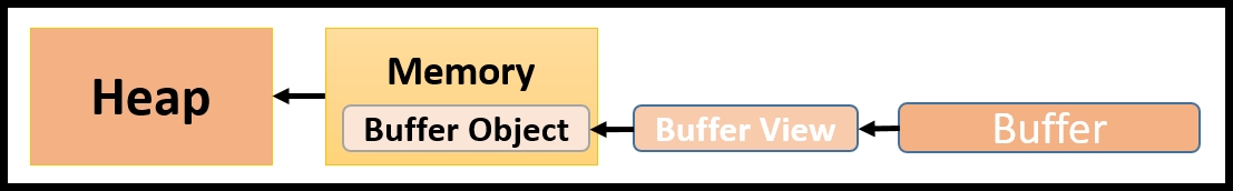
Vulkan divides resources into two types, Buffer and Image, as shown in the following diagram:

These resources are further divided into views; let's understand these:
- Buffer: The buffer object represents resources with linear array types. The buffer object is of the type
VkBufferand is created with thevkCreateBuffer()API. This API takes aVkBufferCreateInfostructure as parameter input, which specifies the various properties that can be used during object creation. For example, you can specify the tiling of an image, usage of an image, size, queue compatibility, and so on. Now let's look at what constitutes a buffer view:- Buffer view: A buffer view (
VkBufferView) represents the data buffer itself. It is used to accommodate the data in a contiguous fashion, in a specific data interpretation format. It can be created with the help of thevkCreateBufferView()API. It accepts theVkBufferViewCreateInfostructure where various buffer-specific properties can be specified, such as its buffer object (VkBuffer), format, the range of the buffer view, and more.
- Buffer view: A buffer view (
- Image: This is programmatically represented by
VkImage. This object stores one- to three-dimensional buffer arrays. The object is created using thevkCreateImage()API. Similar to buffer object, this API uses theVkImageCreateInfostructure to specify various properties during object creation. Now let's look at what an image view is:- Image view: Similar to buffer view, an image view object is of the type
VkImageView. Use thevkCreateImageView()API along with theVkImageViewCreateInfostructure to create the image view object.
- Image view: Similar to buffer view, an image view object is of the type
Let's do a quick recap. So far, we have created a Vulkan instance, a logical device to represent our physical device, and we have queried queue properties and also stored the queue family index that supports the presentation. We have created function pointers for WSI extensions and understood Vulkan resource types. We have also initialized and created our command buffers from the command pool.
That covers all we require to kick off our command buffer recording process.
Tip
What should be recorded into command buffers?
a) Building the drawing image and depth image for swapchain and depth/stencil testing.
b) Creating the shader module to associate with the shader program.
c) Binding resources to the shaders with a descriptor set and pipeline layout.
d) Creating and managing the Render Pass and framebuffer object.
e) Drawing operations.
Start command buffer recording with the vkBeginCommandBuffer(
) API. This defines the starting scope of the command buffer; after this, any command specified will be recorded in the command buffer.
Now, we will learn how to create a swapchain. Here we will acquire the drawing images from the swapchain for rendering purposes:
- Getting surface capabilities: Query the surface capabilities, such as current size, minimum/maximum size possible, possible transformation capabilities, and more, with the
vkGetPhysicalDeviceSurfaceCapabilitiesKHR()API. - Getting surface presentation modes: The presentation mode tells how the drawing surface is going to be updated, for example, whether it is going to be updated in an immediate mode or vertical blank dependent and so on. The presentation modes can be retrieved using the
vkGetPhysicalDevice-SurfacePresentModesKHR()API. - Creating the swapchain: Use the surface capabilities in conjunction with the presentation modes to create the swapchain object. These capabilities, along with many other parameters such as size, surface format, and more, are specified in the
VkSwapChainCreateInfostructure that is passed tovkCreateSwap-chainKHR()to create the object. - Retrieving the swapchain images: Query the number of image surfaces advertised by the swapchain and retrieve the respective image objects (
VkImage) using thevkGetSwapchainImagesKHR()API. For example, if the swapchain supports double buffering, then it should return a count of two and also two images for drawing.Note
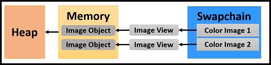
For a swapchain image, there is no memory allocation needed on behalf of the application. Internally, the swapchain has already taken care of memory allocation and returned the baked object. The application only needs to specify how to use this image through image views. An image view describes the use of an image.
- Setting the image layout: For each image, set the implementation-compatible layout and add a pipeline barrier. According to the Vulkan specification, a pipeline barrier inserts an execution dependency and a set of memory dependencies between a set of commands; first it inserts the command buffer and then the set of commands in the command buffer. This can be done using the
vkCmdPipelineBarrier()API. By inserting the barrier, it is guaranteed that the image view will be available in the specified layout before it is used by the application. - Creating an image view: As the application uses only the
VkImageViewobjects, create aVkImageViewobject usingvkCreateImageView(). Save the view objects for application use:/*** 6. Creating Swapchain ***/ //Start recording commands into command buffer vkBeginCommandBuffer(cmd, &cmdBufInfo); // Getting surface capabilities vkGetPhysicalDeviceSurfaceCapabilitiesKHR (gpu, surface, &surfCapabilities); // Retrieve the surface presentation modes vkGetPhysicalDeviceSurfacePresentModesKHR (gpu, surface, &presentModeCount, NULL); VkPresentModeKHR presentModes[presentModeCount]; vkGetPhysicalDeviceSurfacePresentModesKHR (gpu, surface, &presentModeCount, presentModes); // Creating the Swapchain VkSwapchainCreateInfoKHR swapChainInfo = {}; fpCreateSwapchainKHR(device, &swapChainInfo, NULL, &swapChain); // Create the image view of the retrieved swapchain images vkGetSwapchainImagesKHR (device, swapChain, &swapchainImageCount, NULL); VkImage swapchainImages[swapchainImageCount]; vkGetSwapchainImagesKHR (device, swapChain, &swapchainImageCount, swapchainImages); // Retrieve the Swapchain images foreach swapchainImages{ // Set the implementation compatible layout SetImageLayout( . . .) // Insert pipeline barrier VkImageMemoryBarrier imgMemoryBarrier = { ... }; vkCmdPipelineBarrier(cmd,srcStages,destStages,0,0, NULL,0,NULL,1,&imgMemoryBarrier); // Insert pipeline barrier vkCreateImageView(device, &colorImageView, NULL, &scBuffer.view); // Save the image view for application use buffers.push_back(scBuffer); }
The following diagram shows how swapbuffer image objects (VkImage) are used in the form of image view objects (VkImageView):
The application needs a depth image if it intends to use depth testing. For 2D drawing logic, only the swapchain image is enough. The process of depth image creation is the same as the swapchain image. But there is a difference: unlike swapchain images, which are ready-made (returned by vkGetPhysicalDeviceSurfaceFormatsKHR()), the depth image object (VkImage) is allocated and created by the application manually.
The following is the depth image creation process:
- First, query the physical device format properties for the depth image using the
vkGetPhysicalDeviceFormatProperties()API. - Create an image object using the
vkCreateImage()API and get the resource memory requirements with thevkGetImageMemoryRequirements()API. - Next, allocate the memory with the
vkAllocateMemory()API using the retrieved memory requirement properties. Bind the allocated memory to the created image object by calling thevkBindImageMemory()API. - Similar to the swapchain drawing images, set the proper image layout and create an image view for application usage. For more details on device memory allocation, refer to the next section, Resource allocation - allocating and binding device memory.
Refer to the following diagram; the newly allocated depth image is created (VkImage) and connected to its view types (VKImageView) whose object resides in the memory:

The following pseudocode illustrates the creation of the depth image object, this depth image will be used for depth testing purposes:
      /*** 7. Creating Depth image ***/

      // Query supported format features of the physical device
      vkGetPhysicalDeviceFormatProperties(gpus,depthFormat,&properties);

      // Create an image object
      vkCreateImage(device, &imageInfo, NULL, &imageObject);

      // Get the memory requirements for an image resource
      vkGetImageMemoryRequirements(device, image, &memRequirements);

      // Allocate memory
      vkAllocateMemory(device, &memAlloc, NULL, &memorys);

      // Bind memory
      vkBindImageMemory(device, imageObject, mem, 0);

      // Set the implementation compatible layout
      SetImageLayout(. . .)

      // Insert a pipeline barrier to ensure that specified image
      // layout are created before it being used further
      vkCmdPipelineBarrier(cmd, srcStages, destStages, 0, 0, NULL,
                           0, NULL, 1, &imgPipelineBarrier);

      // Create an Image View
      vkCreateImageView(device, &imgViewInfo, NULL, &view);
When first created, Vulkan resources (for buffer, VkBuffer, and for image, VkImage) do not have any backing memory associated with them. Before using a resource, we need to allocate memory to it and bind the resource to the memory.
In order to allocate the Vulkan resource objects, first the application needs to query the available memory on the physical device using vkGetPhysicalDeviceMemory-Properties(). This API advertises one or more heaps and further exposes one or more memory types from these heaps. The exposed properties are stored in a memory control structure (VkPhysicalDeviceMemoryProperties). For a typical PC user, it will expose two heaps: the system RAM and GPU RAM. Further, each of these heaps will be categorized based on their memory types.
Now, each of these memory types can have various properties that need to be queried from the physical device. For example, some memory types could be either CPU-visible or not; they could be coherent between CPU and GPU access, cached or uncached, and so on. Such queries allow the application to choose the right kind of memory that fits their needs, following is the typical process in Vulkan that a general application uses for resource allocation:
- Memory requirements: The resource objects (
VkBufferandVkImage) are created based upon their object properties, such as tiling mode, usage flags, and more. Now, each of these objects may have different memory requirements that need to be queried by callingvkGetBufferMemoryRequirements()orvkGetImageMemoryRequirements(). This is helpful in computing the allocation size; for example, the returned size will take care of the padding alignment and so on. It will take account of the specified bitmask of the memory types that are compatible with the resource.
- Allocation: The memory is allocated using the
vkAllocateMemory()API. It accepts the device object (VkDevice) and a memory control structure (VkPhysicalDeviceMemoryProperties). - Binding: We got the memory requirements that helped us get the right type of memory; using this, we allocate memory. Now we can bind the resource object to this allocated memory using the
vkBindBufferMemory()orvkBindImageMemory()API. - Memory mapping: Memory mapping is how the content of physical device memory is updated. First, map the device memory to the host memory using
vkMapMemory(). Update the content on this mapped memory region (on host the side) and call thevkUnmapMemory()API. This API updates the content of device memory with the updated mapped memory content.
Compile the shader files using glslangValidator.exe (a LunarG SDK tool) to convert them from a readable text format to the SPIR-V format, which is a binary-intermediate form that Vulkan understands:
// VERTEX SHADER
#version 450

layout (location = 0) in vec4 pos;
layout (location = 1) in vec4 inColor;
layout (location = 0) out vec4 outColor;

out gl_PerVertex {
   vec4 gl_Position;
};

void main() {
   outColor    = inColor;
   gl_Position       = pos;
   gl_Position.y = -gl_Position.y;
   gl_Position.z = (gl_Position.z + gl_Position.w) / 2.0;
}

// FRAGMENT SHADER
#version 450

layout (location = 0) in vec4 color;
layout (location = 0) out vec4 outColor;

void main() {
   outColor = color;
};
The following pseudocode shows the process of creating shader modules within an application. A shader module for a given shader (vertex, fragment, geometry, tessellation, and more) is created by calling the vkCreateShaderModule() API. This needs to be provided with the SPIR-V format intermediate binary shader code that is specified in the VkShaderModuleCreateInfo control structure:
/*** 8. Building shader module ***/

VkPipelineShaderStageCreateInfo vtxShdrStages      = {....};
VkShaderModuleCreateInfo moduleCreateInfo    = { ... };

// spvVertexShaderData contains binary form of vertex shader
moduleCreateInfo.pCode = spvVertexShaderData;

// Create Shader module on the device
vkCreateShaderModule
       (device, &moduleCreateInfo, NULL, &vtxShdrStages.module);
A descriptor connects the resources with the shader through layout binding slots. It is very commonly used to connect uniform and sampler resource types to the shaders.
More than one descriptor layout binding can be present in a single descriptor set; they will be present in the form of blocks or arrays, as shown in the following pseudocode. These blocks are then bundled into a single control structure, VkDescriptorSetLayoutCreateInfo, and used to create a descriptor layout object by calling the vkCreateDescriptorSetLayout() API. A descriptor set layout represents the type of information a descriptor set contains.
Descriptor layouts are created but are not presently accessible by the underlying pipeline. In order to provide access, we need to create a pipeline layout. A pipeline layout is the means by which the pipeline can access the descriptor set information. It is created by calling the vkCreatePipelineLayout() API, which consumes a VkPipelineLayoutCreateInfo control structure object containing the preceding descriptor layout:
/*** 9. Creating descriptor layout and pipeline layout ***/


// Descriptor layout specifies info type associated with shaders
VkDescriptorSetLayoutBinding layoutBind[2];

layoutBind[0].descriptorType = VK_DESCRIPTOR_TYPE_UNIFORM_BUFFER;
layoutBind[0].binding       = 0;
layoutBind[0].stageFlags   = VK_SHADER_STAGE_VERTEX_BIT;

layoutBind[1].descriptorType =
 VK_DESCRIPTOR_TYPE_COMBINED_IMAGE_SAMPLER;
layoutBind[1].binding      = 0;
layoutBind[1].stageFlags     = VK_SHADER_STAGE_FRAGMENT_BIT;

// Use layout bindings and create a descriptor set layout
VkDescriptorSetLayoutCreateInfo descriptorLayout = {};
descriptorLayout.pBindings   = layoutBind;

VkDescriptorSetLayout descLayout[2];
vkCreateDescriptorSetLayout
      (device, &descriptorLayout, NULL, descLayout.data());

// Now use the descriptor layout to create a pipeline layout
VkPipelineLayoutCreateInfo pipelineLayoutCI = { ... };
pipelineLayoutCI.pSetLayouts = descLayout.data();
vkCreatePipelineLayout
      (device, &pipelineLayoutCI, NULL, &pipelineLayout);
Note
The present example in this chapter makes use of the attributes only (vertex position and color). It does not use any uniform or sampler. Therefore, at this point in the chapter, we do not need to define the descriptor. We will understand more about descriptor sets in detail later, specifically in Chapter 10, Descriptors and Push Constant.
Next, create a Render Pass object. A Render Pass contains subpasses and attachments. It describes the structure of the drawing work to the driver, how data will flow between the various attachments or what the ordering requirements are; and runtime behavior, such as how these attachments will be treated at each load or whether it needs to be clear or preserve information. The Render Pass object is created by calling the vkCreateRenderPass() API. It accepts the subpass and the attachment control structures as arguments. See the following pseudocode for more information:
/*** 10. Render Pass ***/


// Define two attachment for color and depth buffer
VkAttachmentDescription attachments[2];
attachments[0].format = colorImageformat;
attachments[0].loadOp = clear ? VK_ATTACHMENT_LOAD_OP_CLEAR
                     : VK_ATTACHMENT_LOAD_OP_DONT_CARE;
attachments[1].format = depthImageformat;
attachments[1].loadOp = VK_ATTACHMENT_LOAD_OP_CLEAR;

VkAttachmentReference colorReference, depthReference = {...};

// Describe the subpass, use color image and depth image
VkSubpassDescription subpass     = {};
subpass.pColorAttachments        = &colorReference;
subpass.pDepthStencilAttachment  = &depthReference;

// Define RenderPass control structure
VkRenderPassCreateInfo rpInfo    = { &attachments,&subpass ...};

VkRenderPass renderPass; // Create Render Pass object
vkCreateRenderPass(device, &rpInfo, NULL, &renderPass);
A framebuffer is a collection of image views, corresponding to the attachment specified in the Render Pass. The image view represents the drawing image or depth image. The Render Pass object is used to control these attachments through the properties that are specified while creating the Render Pass object.
The VkFramebufferCreateInfo control structure accepts the Render Pass object and the attachment and other important parameters in it, such as the dimensions, number of attachments, layers, and so on. This structure is passed to the VkCreateFramebuffer() API to create the framebuffer object.
The following diagram shows the created framebuffer object. It contains the image views of the color buffers images for drawing and the depth view for depth testing:

Let's walk through the frame buffer creation process using the following pseudocode:
/*** 11. Creating Frame buffers ***/

VkImageView attachments[2]; // [0] for color, [1] for depth
attachments[1] = Depth.view;

VkFramebufferCreateInfo fbInfo   = {};
fbInfo.renderPass   = renderPass;     // Pass render buffer object
fbInfo.pAttachments  = attachments;   // Image view attachments
fbInfo.width         = width;         // Frame buffer width
fbInfo.height        = height;        // Frame buffer height
// Allocate memory for frame buffer objects, for each image

// in the swapchain, there is one frame buffer
VkFramebuffer framebuffers[number of draw imagein swap chain];

foreach (drawing buffer in swapchain) {
    attachments[0] = currentSwapChainDrawImage.view;
    vkCreateFramebuffer(device, &fbInfo, NULL, &framebuffers[i]);
}
Next, define the geometric shape that will appear on the display output. In this chapter, we used a simple tricolor triangle.
The following screenshot shows the interleaved geometry data associated with this triangle. It contains the vertex position followed by color information for each vertex. This data array needs to be supplied to the physical device via a Vulkan buffer object (VkBuffer).

The following pseudocode involves the allocation, mapping, and binding process of the buffer objects:
/***  12. Populate Geometry - storing vertex into GPU memory ***/

static const VertexWithColor triangleData[] ={
 /*{  x,    y,   z,    w,    r,    g,    b,   a },*/
   {  0.0f,  1.0f, 0.0f, 1.0f, 1.0f, 0.0f, 0.0f, 1.0 },
   { -1.0f, -1.0f, 0.0f, 1.0f, 0.0f, 0.0f, 1.0f, 1.0 },
   {  1.0f, -1.0f, 0.0f, 1.0f, 0.0f, 1.0f, 0.0f, 1.0 },
};

VkBuffer             buffer;
VkMemoryRequirements mem_requirement;
VkDeviceMemory       deviceMemory;

// Create buffer object, query required memory and allocate
VkBufferCreateInfo buffer_info = { ... };
vkCreateBuffer(device, &buffer_info, NULL, &buffer);

vkGetBufferMemoryRequirements(device, buffer, &mem_requirement);

VkMemoryAllocateInfo alloc_info = { ... };

vkAllocateMemory(device, &alloc_info, NULL, &(deviceMemory));

// Copy the triangleData to GPU using mapping and unmapping.
uint8_t *pData;
vkMapMemory(device, deviceMemory, 0, mem_requirement.size,
 0, &pData);
memcpy(pData, triangleData, dataSize); /**** Copying data ****/
vkUnmapMemory(device, deviceMemory);

// Bind the allocated memory
vkBindBufferMemory(device, buffer, deviceMemory, 0);
The process of buffer resource creation is very similar to that of image objects. Here, Vulkan provides buffer-based APIs for allocation, mapping, and binding. This is very similar to image object management APIs. The following table shows buffer and image resource management APIs and related data structures:
|
Buffer object |
Image object |
|
|
|
|
|
|
|
|
|
|
|
|
|
|
|
|
|
|
The buffer is not initially associated with any type of memory. The application must allocate and bind appropriate device memory to the buffer before it can be used. Unlike images, which have to be compulsorily created with the image view in order to use them in the application, the buffer object can be used directly (such as vertex attribute, uniforms, and so on). If the buffer object is required to be accessed in the shader stage, it must be accessed in the form of buffer view objects
Once the vertex data is uploaded in the device memory, the pipeline must be informed with the specification of this data. This will be helpful in retrieving and interpreting the data. For example, the preceding geometry vertex data comprises position and color information, stored in an interleaved fashion, and each attribute is 16-bytes wide. This information needs to be communicated to the underlying pipeline with the help of vertex input binding (VkVertexInputBindingDescription) and the vertex input attribute descriptor (VkVertexInputAttributeDescription) control structure.
- The
VkVertexInputBindingDescriptioncontains properties that help the pipeline to read the buffer resource data, for example, the stride between each unit of information, considering the rate of information to be read (whether it is vertex-based or based on a number of instances). - The
VkVertexInputAttributeDescriptioninterprets the buffer resource data.
In the following pseudocode, the position and color attributes are read at the 0th and 1st location in the vertex shader. Since the data is in interleaved form, the offset is 0 and 16, respectively:
/***  13. Vertex binding ***/

VkVertexInputBindingDescription viBinding;
viBinding.binding    = 0;
viBinding.inputRate  = VK_VERTEX_INPUT_RATE_VERTEX;
viBinding.stride     = sizeof(triangleData) /*data Stride*/;

VkVertexInputAttributeDescriptionviAttribs[2];
viAttribs[0].binding       = 0;
viAttribs[0].location      = 0;
viAttribs[0].format        = VK_FORMAT_R32G32B32A32_SFLOAT;
viAttribs[0].offset        = 0;
viAttribs[1].binding       = 0;
viAttribs[1].location      = 1;
viAttribs[1].format        = VK_FORMAT_R32G32B32A32_SFLOAT;
viAttribs[1].offset        = 16;
A pipeline is a collection of multiple states. Each state contains a set of properties that defines an execution protocol for that state. Collectively, all these states produce a single pipeline. There are two types of pipeline:
- Graphics pipeline: This pipeline may comprise multiple shader stages, including vertex, fragment, tessellation, geometry, and so on. It has a pipeline layout and multiple fixed-function pipeline stages.
- Compute pipeline: This is used for the compute operation. It consists of a single static compute shader stage and the pipeline layout.
Pipeline state management can be divided into two steps. The first step consists of defining various state objects containing important state control properties. In the second step, a pipeline object is created using these state objects.
A pipeline may consume several states, and these are defined here:
- Dynamic states: The dynamic state notifies the pipeline about what states are expected to change at runtime. This allows the pipeline to permit a special routine update to the respective state instead of using an initialized value. For example viewport and scissoring are dynamic states. The
VkPipelineDynamicStateCreateInfostructure specifies all dynamic states and their properties in the application program. - Vertex input state: This state helps the pipeline to understand the reading and interpretation of data. Use the
VkPipelineVertexInputStateCreateInfoobject and specify the object of vertex input binding (VkVertexInputBindingDescription) and the vertex input attribute descriptor (VkVertexInputAttributeDescription) in it. - Rasterization state: This is the process by which a primitive is converted into a two-dimensional image containing vital information, such as color, depth, and other attributes. It is represented by the
VkPipelineRasterizationStateCreateInfostructure; this structure can be specified with culling mode, front-face orientation, primitive type, line width, and more. - Color blend attachment state: Blending is a combination of a source and a destination color; this can be combined in various ways with different attributes and blend equations. This is represented using the
VkPipelineColor-BlendStateCreateInfostructure. - Viewport state: This state is helpful in controlling the viewport transformation. The viewport properties can be specified using
VkPipelineViewportState-CreateInfo. There could be various viewports. This state helps in determining the vital properties of the selected viewport, such as dimension, start point, depth range, and more. For each viewport, there is a corresponding scissor rectangle defining the scissor test rectangular bounds.
- Depth stencil state: The
VkPipelineDepthStencilStateCreateInfocontrol structure is used to control the depth bound tests, stencil test, and depth test. - Multisample state: The multisampling state contains important properties that control the behavior of the antialiasing of rasterized Vulkan primitives, such as points, lines, and polygons. The
VkPipelineMultisampleStateCreateInfocontrol structure can be used to specify such control properties. - The following pseudocode defines the various pipeline state objects that will be used in creating the graphics pipeline:
      /*** 14. Defining states ***/


      // Vertex Input state
      VkPipelineVertexInputStateCreateInfo vertexInputStateInfo= {...};
      vertexInputStateInfo.vertexBindingDescriptionCount = 1;
      vertexInputStateInfo.pVertexBindingDescriptions    = &viBinding;
      vertexInputStateInfo.vertexAttributeDescriptionCount     = 2;
      vertexInputStateInfo.pVertexAttributeDescriptions  = viAttribs;

      // Dynamic states
      VkPipelineDynamicStateCreateInfo dynamicState            = { ... };

      // Input assembly state control structure
      VkPipelineInputAssemblyStateCreateInfo inputAssemblyInfo= { ... };

      // Rasterization state control structure
      VkPipelineRasterizationStateCreateInfo rasterStateInfo  = { ... };

      // Color blend Attachment state control structure
      VkPipelineColorBlendAttachmentState colorBlendSI   = { ... };

      // Color blend state control structure
      VkPipelineColorBlendStateCreateInfo colorBlendStateInfo = { ... };

      // View port state control structure
      VkPipelineViewportStateCreateInfo viewportStateInfo      = { ... };

      // Depth stencil state control structure
      VkPipelineDepthStencilStateCreateInfo depthStencilStateInfo={..};

      // Multisampling state control structure
      VkPipelineMultisampleStateCreateInfo multiSampleStateInfo = {..};
Pipeline state objects are packed into the VkGraphicsPipelineCreateInfo control structure. This structure provides a means to access the pipeline state information inside the graphics pipeline object.
The creation of the pipeline state object could be an expensive operation. It is one of the performance-critical paths. Therefore, pipeline state objects are created from a pipeline cache (VkPipelineCache) to offer maximum performance. This allows the driver to create a new pipeline using existing base pipelines.
The graphics pipeline object is created using the vkCreateGraphicsPipelines() API. This API accepts the pipeline cache object to allocate the VkPipeline object from it and the VkGraphicsPipelineCreateInfo object to specify all the states connected with this pipeline:
/***  15. Creating Graphics Pipeline ***/

// Create the pipeline objects
VkPipelineCache pipelineCache;
VkPipelineCacheCreateInfo pipelineCacheInfo;
vkCreatePipelineCache(device, &pipelineCacheInfo, NULL,
                     &pipelineCache);

// Define the control structure of graphics pipeline
VkGraphicsPipelineCreateInfo pipelineInfo;
pipelineInfo.layout              = pipelineLayout;
pipelineInfo.pVertexInputState   = &vertexInputStateInfo;
pipelineInfo.pInputAssemblyState = &inputAssemblyInfo;
pipelineInfo.pRasterizationState = &rasterStateInfo;
pipelineInfo.pColorBlendState    = &colorBlendStateInfo;
pipelineInfo.pMultisampleState   = &multiSampleStateInfo;
pipelineInfo.pDynamicState       = &dynamicState;
pipelineInfo.pViewportState      = &viewportStateInfo;
pipelineInfo.pDepthStencilState  = &depthStencilStateInfo;
pipelineInfo.pStages             = shaderStages;
pipelineInfo.stageCount          = 2;
pipelineInfo.renderPass          = renderPass;

// Create graphics pipeline
vkCreateGraphicsPipelines
      (device, pipelineCache, 1, &pipelineInfo, NULL, &pipeline);
We are almost there! At this stage, we will render our simple triangle on the drawing surface with the help of the Render Pass stage. The execution of the Render Pass stage requires a drawing surface and a recording of a set of commands that defines a single Render Pass run.
The very first thing we require before we start rendering anything is the drawing framebuffer. We have already created the framebuffer object and associated the swapchain drawing image within it (containing the swapchain image views). Now, we will use the vkAcquireNextImageKHR() API to determine the index of the drawing image that is currently available for the drawing operation. Using this acquired index, we refer to the corresponding framebuffer and give it to the Render Pass stage for rendering purposes:
/***  16. Acquiring drawing image ***/


// Define semaphore for synchronizing the acquire of draw image.

// Only acquire draw image when drawing is completed
VkSemaphore imageAcquiredSemaphore;
VkSemaphoreCreateInfo imageAcquiredSemaphoreCI = {...};
imageAcquiredSemaphoreCI.sType=VK_STRUCTURE_TYPE_SEMAPHORE_CREATE_INFO;
vkCreateSemaphore(device, &imageAcquiredSemaphoreCI, NULL,
                     &imageAcquiredSemaphore);

// Get the index of the next available swapchain image:
vkAcquireNextImageKHR(device, swapChain, UINT64_MAX,
   imageAcquiredSemaphore, NULL, &swapChainObjCurrentBuffer);
A synchronization mechanism is required when two or more swapchain drawing images are being used. A drawing image must only be acquired if it has rendered on the display output and is ready to take the next job; this status is indicated by vkAcquireNextImageKHR(). A semaphore object can be used to synchronize the acquiring of the drawing images. A semaphore (VkSemaphore) can be created using the vkCreateSemaphore() API; this object will be used in the command buffer submission.
Render Pass needs some specific information, such as the frame buffer, Render Pass object, render area dimensions, clear color, depth stencil values, and so on. This information is specified using the VkRenderPassBeginInfo control structure. This structure is later used to define Render Pass execution. The following pseudocode will help you understand the use of this structure in detail:
/***  17. Preparing render pass control structure ***/


// Define clear color value and depth stencil values
const VkClearValue clearValues[2] = {
   [0] = { .color.float32 = { 0.2f, 0.2f, 0.2f, 0.2f } },
   [1] = { .depthStencil = { 1.0f, 0 } },
};

// Render pass execution data structure for a frame buffer
VkRenderPassBeginInfo beginPass;
beginPass.sType = VK_STRUCTURE_TYPE_RENDER_PASS_BEGIN_INFO;
beginPass.pNext= NULL;
beginPass.renderPass  = renderPass;
beginPass.framebuffer =framebuffers[currentSwapchainImageIndex];
beginPass.renderArea.offset.x          = 0;
beginPass.renderArea.offset.y          = 0;
beginPass.renderArea.extent.width      = width;
beginPass.renderArea.extent.height     = height;
beginPass.clearValueCount              = 2;
beginPass.pClearValues                 = clearValues;
The execution of the Render Pass is defined within a user-defined scope. This scope is interpreted using start and end markers defined by the vkCmdBeginRenderPass() and vkCmdEndRenderPass() APIs respectively. Within this scope, the following commands are specified, automatically linked to the current Render Pass:
- Bind the pipeline: Bind the graphics pipeline with
vkCmdBindPipeline(). - Bind the geometry buffer: Supply the vertex data buffer object (of the type
VkBuffer) to the Render Pass using thevkCmdBindVertexBuffers()API. - Viewport and scissor: Specify the viewport and scissor dimensions by calling the
vkCmdSetViewport()andvkCmdSetScissor()APIs. - Draw object: Specify the draw command containing information such as how many vertices need to read from the start index, the number of instances, and so on.
Before we finish command buffer recording, set an implementation-compatible image layout and end command buffer recording by calling vkEndCommandBuffer():
/**** START RENDER PASS ****/
vkCmdBeginRenderPass(cmd, &beginPass, VK_SUBPASS_CONTENTS_INLINE);

// Bind the pipeline
vkCmdBindPipeline(cmd, VK_PIPELINE_BIND_POINT_GRAPHICS, pipeline);
const VkDeviceSize offsets[1] = { 0 };

// Bind the triangle buffer data
vkCmdBindVertexBuffers(cmd, 0, 1, &buffer, offsets);

// viewport = {0, 0, 500, 500, 0 ,1}
vkCmdSetViewport(cmd, 0, NUM_VIEWPORTS, &viewport);

// scissor  = {0, 0, 500, 500}
vkCmdSetScissor(cmd, 0, NUM_SCISSORS, &scissor);

// Draw command - 3 vertices, 1 instance, 0th first index
vkCmdDraw(cmd, 3, 1, 0, 0);

/**** END RENDER PASS ****/
vkCmdEndRenderPass(cmd);

// Set the swapchain image layout
setImageLayout(VK_IMAGE_LAYOUT_COLOR_ATTACHMENT_OPTIMAL . .);

/**** COMMAND BUFFER RECORDING ENDS HERE ****/
vkEndCommandBuffer(cmd);
The following diagram shows the Render Pass execution process. It highlights the operations performed under the Render Pass scope.

Finally, we have reached a point where our command buffer is successfully recorded with numerous commands, including the Render Pass information and the graphics pipeline. The command buffer will be processed by submitting it into the queue. The driver will read the command buffer and schedule it.
Before a command buffer is submitted, it's important to know the status of the previously submitted batch. If it is processed successfully, then it only makes sense to push a new batch into the queue. Vulkan provides fences (VkFence) as a synchronization mechanism to know whether the previously sent jobs have been completed. A fence object (VkFence) is created using the vkCreateFence() API. This API accepts a VkFenceCreateInfo control structure into it.
Command buffers are specified in a submission object (VkSubmitInfo). This object contains the command buffer list along with a VkSemaphore object for the synchronization of a framebuffer with swapchain drawing images. This information is fed into the vkQueueSubmit() API; it contains a VkQueue object to which the command buffer is going to be submitted and a VkFence object to ensure there is synchronization between each command buffer submission:
VkFenceCreateInfo fenceInfo = { ... };
VkFence drawFence;
// Create fence forensuring completion of cmdBuffer processing
vkCreateFence(device, &fenceInfo, NULL, &drawFence);

// Fill the command buffer submission control sturctures
VkSubmitInfo submitInfo[1] = { ... };
submitInfo[0].pNext        = NULL;
submitInfo[0].sType        = VK_STRUCTURE_TYPE_SUBMIT_INFO;
submitInfo[0].pWaitSemaphores    = &imageAcquiredSemaphore;
submitInfo[0].commandBufferCount = 1;
submitInfo[0].pCommandBuffers    = &cmd;

// Queue the command buffer for execution
vkQueueSubmit(queue, 1, submitInfo, NULL);
Once the command buffer is submitted to the queue, it is processed asynchronously by the physical device. As a result, it will render a tricolor triangle on the drawing surface of the swapchain. Now, this surface is invisible to the user and it needs to be presented on the display window. The drawing surface is presented with the help of the VkPresentInfoKHR control structure. This contains the presentation information, for example, the number of swapchains in the application, the index of a drawing image that needs to be retrieved, and so on. This control structures object is used as a parameter in vkQueuePresentKHR. This flips the drawing surface image to the display window.
// Define the presentation control structure
VkPresentInfoKHR present   = { ... };
present.sType              = VK_STRUCTURE_TYPE_PRESENT_INFO_KHR;
present.pNext              = NULL;
present.swapchainCount     = 1;
present.pSwapchains        = &swapChain;
present.pImageIndices      = &swapChainObjCurrent_buffer;

// Check if all the submitted command buffers are processed
do {
  res=vkWaitForFences(device,1,&drawFence,VK_TRUE,FENCE_TIMEOUT);
} while (res == VK_TIMEOUT);

// Handover the swapchain image to presentation queue

// for presentation purpose
vkQueuePresentKHR(queue, &present);

// Destroy Synchronization objects
vkDestroySemaphore(device, imageAcquiredSemaphore, NULL);
vkDestroyFence(device, drawFence, NULL);