
In this chapter, we will introduce the concept of functional design in Inventor 2010. The functional design tools enable you to create complex geometry by entering size data. Before any geometry is created, you can verify whether the design meets the requirements by performing calculations. The formulas used for the calculations are based on international standards, and they are fully documented in the Engineer's Handbook. This allows you to override or ignore certain calculations when experience dictates.
In this chapter, you'll learn to:
Use Inventor's Design Accelerators
Use Inventor's Design Calculators
Understand the interaction of these tools with Content Center
Develop best practices for using these tools
In most industries, product requirements and design criteria drive the engineering process. As its name implies, functional design favors function over geometry. Rather than modeling geometry first and then hoping that the form satisfies all the design criteria, in the functional design method the designer or engineer makes sure the product operates correctly given the design criteria prior to finalizing the product's shape. If functional design is done well, the geometry will be the result of the design process rather than the input to it.
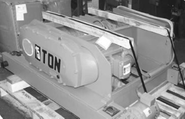
A 15-Ton Hoist Machine
Many of the examples in this chapter are taken from the 15-ton hoist depicted here. The hoist has a full gearbox and brake system, which is situated in the front-left side of the machine. The different components of the machine were generated through classic part and assembly modeling. However, for the dynamic study of the different components and the analysis of the forces and the power transmission, Inventor's Gear Generator was extensively used.
This chapter will concentrate on the Design Accelerator tools that Inventor offers to mechanical and electrical engineers so they can concentrate on the product requirements rather than spending most of their time creating geometry.
Most of the topics in this chapter require an assembly to be opened. Therefore, this chapter is not applicable if you have only Inventor LT installed.
You've probably been confronted with several of the design criteria listed here. They are typical requirements that a design engineer will have to satisfy (in no particular order):
Strength (material, size, weight, load conditions, mechanical behavior, safety factors)
Power (speed, torque, momentum, power transmission, lubrication, safety)
Temperature (cooling, heat dissipation)
Vibration and motion (frequency response/Eigen values/damping)
Wear resistance (surface treatments, plating, tolerances/life cycle/wear/durability/lubrication)
Sound restrictions/considerations (insulation/packaging)
Optical characteristics (color, surface characteristics, refraction, transparency, chromatic aberration, aesthetics)
Electrical and magnetic characteristics
Cost (materials, packaging, eco-sustainability, spare parts, stock parts, standard sizes vs. custom made, maintenance, manufacturing and assembly methods, time restrictions)
Often these requirements will conflict with one another; for example, improving strength or durability often will increase cost, and so on.
As a design engineer, you often use tools that help make the right trade-off by attempting to verify and optimize the design by using lab tests, calculations, stress analysis, rendering, and animations.
In this chapter, you will use the built-in calculation rules of the Design Accelerators in combination with animations and the Engineer's Handbook to satisfy the strength, power, wear, and temperature requirements of a particular design. While doing so, we will show some real-world examples to illustrate functional design concepts. To underline the diversity of the tool, we will show examples spanning various industries, such as engine design (springs and cams), and power transmission design (gearbox).
Inventor's Design Accelerators can be overwhelming at first because of the sheer number of accelerators and because the user interface is slightly different from the rest of Inventor. Therefore, we'll look at the dialog boxes, the browser structure, and the user interface for these tools.
Inventor's Design Accelerators are available only in the assembly environment. Design Accelerator dialog boxes are tabbed dialog boxes, as shown in Figure 11.1. The Design and Calculation tabs appear in most of the dialog boxes. Two particular areas in these dialog boxes are worth pointing out. The Results pane displays the calculated values for a particular design. The Summary pane indicates whether a design is acceptable with the given parameters. These panes are hidden by default and can be displayed by double-clicking on the double line on the right and bottom edges of the dialog box or by clicking the chevron/arrows along the borders. The border of the Design Accelerator window turns red to indicate a design failure or to flag a more general error.

The calculation is not an automatic operation; for example, if a calculation fails and the values turn red, you typically change the parameters to correct the problem. You will not see the result of your change unless you explicitly click the Calculate button. Many calculators offer different types of calculations. Choosing a particular calculation method will disable certain fields (driven values) and enable some other fields (input values).
Figure 11.2 and Figure 11.3 show an example dialog box (belt) that shows how its fields will look like if you are calculating the power from the torque and speed (Figure 11.2) vs. calculating the torque with the power and speed as inputs (Figure 11.3).
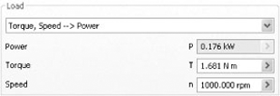
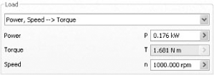
Table 11.1 shows the icons and buttons that appear in all the Design Accelerator dialog boxes. It will help if you familiarize yourself with them before diving into the rest of this chapter.
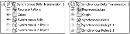
There are two sorts of functional design tools: generators and calculators. It is important to understand the difference between these two categories. The output generated by Design Generators consists of subassemblies with actual geometry in them. The output generated by the Design Calculators (that is, the weld or plate calculators) consists only of a subassembly browser node. The calculators don't generate any geometry, but the result of the calculation can be edited and repeated with different values. The solve state of the subassemblies is indicated by an icon in the browser. Manual Solve is the default mode, but you can change it to Automatic Solve by right-clicking on the Design Accelerator component and selecting Component and then the solve mode you want to use. Figure 11.4 shows the Manual Solve icon on the left and Automatic Solve on the right.
Table 11.1. Common Design Accelerator Dialog Box Elements
Icon | Function |
|---|---|
Export to a template | |
Import a template | |
File naming | |
Disable/enable calculation | |
Reset calculation data | |
Display results in HTML format | |
Expand/collapse the summary window | |
Expand/collapse the result window | |
More options | |
Select a different size or different properties | |
Select a different type | |
Delete a selection |
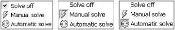
There are three solve states that can be changed in the Component context menu, as described in Table 11.2.
Table 11.2. Solve States of Design Accelerator Components
State | Explanation |
|---|---|
Solve Off | Changes to Design Accelerator input conditions have no effect on the Design Accelerator component. |
Manual Solve | Changes to Design Accelerator input conditions only have an effect after editing the Design Accelerator component. |
Automatic Solve | Changes to Design Accelerator input conditions immediately affect the Design Accelerator component. |
The Solve Off, Manual Solve, and Automatic Solve options are mutually exclusive, meaning that when you select one option it turns the current one off. The Solve Off menu does exactly what its name suggests: it turns off the solver completely so that the Design Accelerator component is frozen until the next edit. The possible solve states are reflected in the context menu, as shown in Figure 11.5.
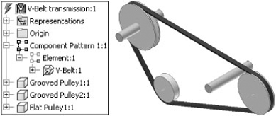
The difference between Manual Solve and Automatic Solve is simple. Let's take the example of a V-belt. When the distance between the axes changes, a V-belt will automatically readjust the pulley positions if Automatic Solve is on. If Manual Solve is on, the user will have to update the pulley position by clicking the Manual Solve menu. A red lightning bolt will appear in the browser, as shown in Figure 11.6. Manual Solve is used as the default for performance reasons and to prevent interactions with the assembly solver.
The Calculate option on the context menu is a toggle between two states; clicking it once turns it on, and clicking it again turns it off. You can do this by using the Calculate button at the top right of each Design Accelerator dialog box as well. When calculation is turned off, the performance of the generator is faster.
Because Design Accelerator assemblies typically consist of multiple parts that are constrained together, Inventor offers specific edit, delete, promote, and demote tools to handle these more complex entities. Figure 11.7 shows the edit and delete tools.
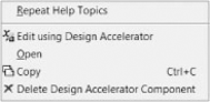
Figure 11.8 shows the promote and demote tools that are available on some generators only: gears, belts, cams, and shafts. Use these tools to demote Design Accelerator components out of their original Design Accelerator subassembly. This allows the grouping of components of different Design Accelerator assemblies into a single subassembly. You can edit a demoted component on the original Design Accelerator assembly by using the Edit Using Design Accelerator tool.
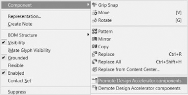
Be sure to set the Inventor selection priority to Components before you select Design Accelerator components; otherwise, you won't see the special tools.
Although you should generally avoid editing the subassembly itself using the traditional edit method and instead use the Edit Using Design Accelerator tools, components in the subassembly can be edited under certain circumstances. Copying or patterning Design Accelerator assemblies will maintain the geometry, but you will lose the ability to edit the copied assembly with the Edit Using Design Accelerator tool, which basically means you lose the Design Accelerator intelligence on the copy.
Most design generators use Content Center parts, but not all. Consult Table 11.3 when you don't have access to Content Center and still want to use some of the Design Accelerators.
Table 11.3. Design Accelerators' Use of Content Center Database
Generator/Accelerator | Needs Content Center |
|---|---|
Bolted Connections | Yes |
Weld Calc | No |
Tolerance Stack Up Calc | No |
Limits and Fits Calc | No |
Beam Calc | No (but recognizes section properties of Content Center and Frame Generator parts; see Chapter 15) |
Column Calc | No (but recognizes section properties of Content Center and Frame Generator parts; see Chapter 15) |
Plate Calc | No |
Shaft Generator | No |
Cam Generator | No |
Gear Generator | No |
Bearing Generator | Yes |
Key Connection Generator | Yes |
Spline Generator | No |
Belt Generator | No |
Sprocket and Chain Generator | Yes |
Spring Generator | Yes (but only for Belleville springs) |
Pins Generator | Yes |
Seals and O-rings Generator | Yes |
Engineer's Handbook | No |
This generator is the most popular Design Accelerator tool because it is able to make an entire set of bolts, washers, nuts, and the necessary holes in the supporting geometry as an all-in-one operation. Figure 11.9 shows placement options for the Bolted Connections tool; you might notice the similarity between these options and the Hole tool placement options.
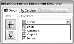
There are four placement options:
Linear allows the creation of a bolted connection without any preexisting sketch by selecting a distance to two different linear edges.
Concentric uses any circular edge (the edge does not have to be part of a hole feature; the edge can be part of a cylindrical extrusion) to make a bolted connection with a larger or smaller hole size.
By Hole requires an existing hole, and the bolted connection will incorporate the existing hole.
On Point requires an existing work point or vertex as input.
Although the Bolted Connections tool will create holes for you, it is often best to create the holes first with the regular Hole tool and then use the By Hole option rather than using the Linear or Concentric option. The disadvantage of the latter two options is that it creates only a point in a sketch, but the point is not dimensioned and could easily move. When the sketch point moves, the bolted connection will not follow the new position of the hole. When you use By Hole, the bolted connection will automatically follow any positional change of the preexisting holes but will not follow diameter changes automatically. Keeping the diameter of the holes generated by the bolted connection in sync with the diameter changes in the preexisting hole requires manually selecting a different diameter in the Diameter field of the bolted connection. The reason this was done is to give you a choice because you don't necessarily want all your bolts to increase in diameter when the underlying hole diameter increases.
Enough theory—now let's concentrate on an actual example, the assembly called mi_11a_001.iam from the Chapter 11 folder. You need to connect the brown cap with the blue plate. The cap has three holes drilled in it, and they form a circular pattern. The plate has no holes yet, and this can be verified by activating the view representation called Section. The design problem you are trying to solve is the following: considering an axial force of 750N and a tangential force of 300N, will three bolts be sufficient to hold the cap on the plate?
As mentioned, to respect the existing hole pattern in the cap and create the necessary holes in the plate, you start the Bolted Connection command first and follow these steps:
On the Get Started tab, click Open and browse to
mi_11a_001.iamin the Chapter 11 folder.Select the Design tab and then click the Bolted Connection button.
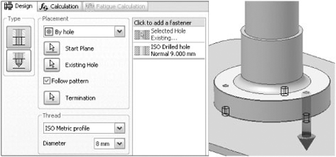
In the Placement area, confirm that By Hole is selected in the drop-down list.
Select the top face of the cap as the Start Plane.
Select one of the holes. Since there is a hole pattern, the preview will display at the original instance of the hole no matter which hole you select. Note too that the Follow Pattern option is displayed in the Bolted Connection dialog box. Check the box so all of the holes will get fasteners.
Click the Termination button and select the back side of the plate. The Bolted Connections Generator is smart enough to know which side of the plate is valid for termination. When you hover over the plate, the back side highlights and you can click to accept.
In the Thread area, set the Diameter to 8mm to match the holes in the cap. In Figure 11.10, you can see that holes have been added to the dialog browser pane.
Note that there are three drilled holes automatically added to the blue plate. You could click the Drilled Hole bar in the right pane and then click the down arrow to select a different hole type (for example, counter bore). The Bolted Connections Generator is clever enough to filter out countersink hole types for holes on faces that are not exposed.
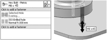
At this point, you can add all necessary hardware to finish the connection. It is important to note that the order of the icons in the pane on the right represents the stacking order of the bolted connection beginning from the start plane down. If you want to place a bolt on the start plane, you just click the area marked with Click To Add A Fastener.
Click the area marked Click To Add A Fastener above the holes. The bolt is long enough to go through the components. If you want to change the bolt length, drag the arrows at the end. Only valid lengths from Content Center can be selected. Figure 11.11 shows the bolt preview and the length adjustment arrow.
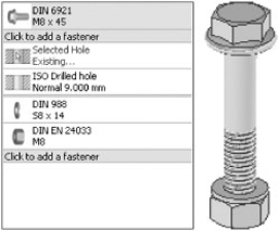
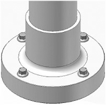
To finish the bolted connection by adding a nut and washer, click the area marked Click To Add A Fastener below the holes and select a DIN 988 washer. Click again and select a DIN EN 24033 nut. The completed bolted connection is shown in Figure 11.12.
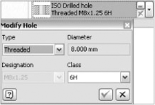
If you wanted to thread the plate to avoid adding a nut and washer, you could do so by clicking the...icon in the ISO Drilled hole section of the pane, as shown in Figure 11.13.
The Calculation tab provides four strength calculation options:
Do you meet the design criteria with just three bolts? It all depends on the material you choose for the bolts.
Switch to the Calculation tab and confirm that Number Of Bolts Design is selected in the Type Of Strength Calculation area.
In the Loads area, enter 750N for Maximal Axial Force and 300N for Maximal Tangent Force.
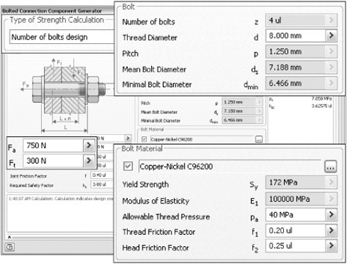
This application requires fasteners with high thermal conductivity. In the Bolt Material area, check the box next to the field and select Copper-Nickel C96200. To narrow down the material choices, type Copper in the text field below the Material column header. Note that the text filter is case sensitive.
Click Calculate to analyze the fasteners. You can see in Figure 11.14 that we need four fasteners for these load and fastener materials.
Click OK to set the bolted connection to the current hole pattern of three holes.
To comply with the calculation, you need to update the hole pattern in the cap from three to four members, and the bolted connection pattern follows accordingly, as shown in Figure 11.15 (if Automatic Solve is on) or after expanding the pattern, right-clicking on the bolted connection, and then clicking Component
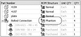
Like many Design Accelerator assemblies, the bolted connection subassembly shown in Figure 11.16 is a phantom subassembly, which means that only its subcomponents are shown at the parent level in the BOM.
If you edit the plate, the holes in the plate have a lock symbol next to their icon in the browser, indicating that they are generated by a Design Accelerator and can be modified only by that same Design Accelerator. Proof of this is that the Edit Feature command or the "double-click to edit" behavior is absent for these type of holes. If you want the hole in the plate to be independent from the Design Accelerator they were generated by, use the Explode context menu on the hole.
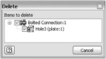
As explained earlier, the bolted connection makes the holes automatically for you. In a similar fashion, if you remove a bolted connection you can choose to remove the associated holes if you want, as shown in Figure 11.17.
Inventor has several Design Calculators that perform a specific calculation without generating any geometry. The dialog box for calculators is also restricted to one tab, the Calculation tab. Calculators do generate a node in the assembly browser, which allows you to repeat the calculation with different input values. We'll cover the weld calculator in more detail than the others because all the calculators (weld, solder and hub joints, power screw, tolerance) are very similar.
There are a few interesting things to note about the weld calculator:
There is no automatic link between the weld assembly and the weld calculator. To obtain the beam height, beam width, and weld height, use the Measure drop-down menu under the right arrow of the real value edit controls inside the calculator window, and proceed with measuring the weld bead in the model. Do not use the Measure commands in the Tools menu because this will exit the Design Accelerator dialog box. An alternative is to measure and copy these distances to the clipboard prior to entering the calculator and then paste them into the calculator.
The actual weld results are stored as a subassembly without any geometry in the main assembly.
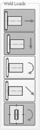
Weld loads can be combined. The example in Figure 11.18 shows a combination of axial force, bending force, and torque.
Weld results can be edited or can be exported to HTML files for viewing in a web browser.
Fatigue calculation is not on by default; you have explicitly turn it on by clicking the second icon at the top right of the dialog box.
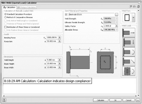
Here is the functional design problem that you can solve with the weld calculator: what combination of weld bead material and weld height should you use for a given safety factor so that the weld withstands a lateral point force (3000N) at a distance of 50mm from the weld plane?
To calculate the weld requirements, follow these steps:
On the Get Started tab, click Open and browse to
mi_11a_003.iamin the Chapter 11 folder.On the Weld tab, click the Weld Calculator drop-down and select Fillet Weld Calculator (Spatial).
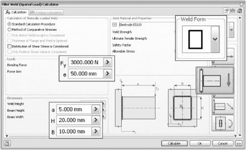
In the Weld Form area, select the rectangle from the drop-down list.
In the Weld Loads area, select Bending Force Parallel With The Weld Plane and deselect the default, Axial Force Perpendicular To The Weld Plane. Note that at least one calculation type must be active, so you have to select the new type before deselecting the default one.
In the Loads area, enter a Bending Force value of 3000N and a Force Arm value of 50mm.
In the Dimensions area, enter 5.0mm for Weld Height, 20mm for Beam Height, and 10mm for Beam Width. See Figure 11.19 for the dialog box entries.
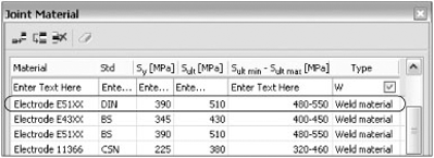
In the Joint Material and Properties area, check the box next to the User Material field to specify a material. Type W in the field under the Type column header to filter for weld materials, as shown in Figure 11.20. The filter is case sensitive. Select E51XX as the material and click OK.
You can now finally click the Calculate button, and all values will be displayed in black (not red) in the Results window, as shown in Figure 11.21. At the same time, the message "Calculation indicates design compliance!" will appear in the Summary window.
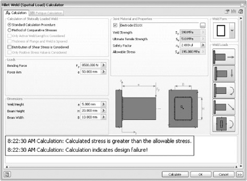
We will now explore an additional what-if scenario. What will happen if the anticipated force of 3000 is higher and you have a force of 8500N? You will most likely have to increase the weld height or the weld material to avoid breakage if you pursue the same safety factor of 2x.
Follow these steps to calculate the new weld bead requirements.
Edit the Fillet Weld calculation and enter 8500N as the Bending Force.
Click Calculate. When one or more results values are marked in red, as shown in Figure 11.22, an error message displays in the Results window. The calculator has determined that the minimum weld height, amin, is 6.658mm.
Set Weld Height to 7mm, and click Calculate. The calculation results show that the weld meets the required factor. If you wanted to maintain the same weld height, you could select a weld material that has a higher yield strength.
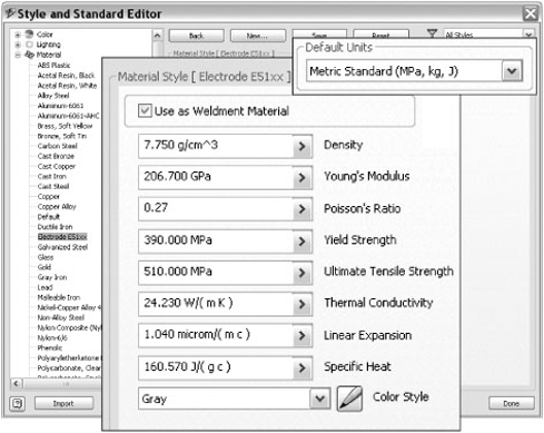
It is interesting to note that there is no relationship between materials as defined in the Design Accelerator dialog boxes and materials as defined in the Inventor style library.
To complete the exercise and to keep the calculator in sync with the actual assembly, two things need to happen. First, it would be good to also create the material E51xx in the Style And Standard Editor, as shown in Figure 11.23; mark it as a weldment material; and assign this material to the weld bead properties. If you are planning on using this material on a regular basis, it would be even a better idea to add this material to the style library so you can use it in every weldment assembly via a template file.
Second, if we plan to use our original material Electrode E51xx, we need to change the weld height to 7.5mm in the weld beads of our assembly.
You used only one type of weld calculator. In Inventor there are different weld calculators for each weld type (fillet weld, butt weld, plug and groove weld, spot weld, bevel joint, lap joint, tube joint), but all use methods similar to the one explained earlier. So, it should be pretty straightforward to find your way around in the other weld calculators.
The majority of the modules in the Design Accelerator add-in are generators. Generators not only perform calculations, but they also automatically generate the underlying geometry. This can be a real time-saver especially when you are talking about complex geometry such as helical gears or chains or synchronous belts. You will take an in-depth look at several of these generators.
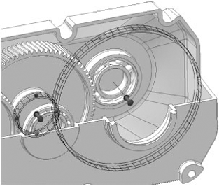
There are three gear families in Inventor: Spur Gears, Bevel Gears, and Worm Gears. We will explain the use of spur gears in the design of the gearbox shown in Figure 11.24.
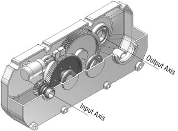
The output axis depicts the driving or motor side, and the input axis depicts the driven or load side. The design challenge in this gearbox is to add the remaining gear pair to connect to the output axis while fulfilling the power requirements on that axis (7.5kW) and the speed requirements (260rpm) and to select a gear material that guarantees a minimum life cycle of 15,000hr.
To complete this exercise correctly and to get the same values as shown in the figures, be sure to choose the same options as explained in this section.
In this example, you will add a gear pair between the output axis and the middle axis closest to the output axis, as shown in Figure 11.24. The gear on the input axis (Gear 2) will be the larger gear. The gear on the middle axis (Gear 1) will be the smaller gear.
Follow these steps to create the gears:
On the Get Started tab, click the Open button.
Browse for the file named
mi_11a_005.iamlocated in the Chapter 11 directory of the Mastering Inventor 2010 folder, and click Open.Activate the View Representation called Mastering Inventor.
On the Design tab, click the Spur Gear button found on the Power Transmission panel. Note that if you've used the Worm or Bevel Gear tools last you may need to use the drop-down to locate the Spur Gear button.
Expand the More options by clicking the >> button and set Input Type to Gear Ratio.
In the Common section, change Design Guide to Module. Enter 3.6 in the Desired Gear Ratio field. Enter 8 degrees in the Helix Angle field.
For Gear 1, select the cylindrical face of the bearing (or any of the green faces) and the Red face of Gear 4. Set the number of teeth to 19.
For Gear 2, select the cylindrical face of the bearing (or any of the yellow faces). Confirm that Facewidth for both gears is 20mm.
When you click Calculate, the preview will update as shown in Figure 11.25. If an error is displayed, check all of the inputs.
By choosing the Module Design Guide, you also determined the module value (this value is read-only in this method, which is indicated by its field being grayed out).
After satisfying the space and position requirements, you'll now concentrate on selecting the right material for the gears to satisfy the power and speed requirements.
Activate the Calculation tab, and set Method Of Strength Calculation to ISO 6336:1996.
Expand the More options by clicking the >> button and confirm Type Of Load Calculation is set to Power, Speed → Torque because power and speed are known inputs.
In the Material Values area, check the boxes to enable material selection for Gear 1 and Gear 2. Choose 37Cr4 with a face-hardened heat treatment for Gear 1 and 30CrMoV6 4 for Gear 2.
In the Loads area, enter 7.5kW for the power and 260rpm for the speed.
Set Required Life to 15000hr.
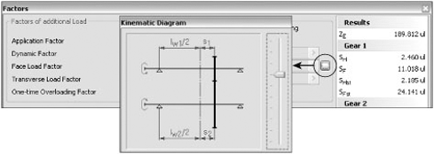
Click the Factors button to change load and lubrication parameters. The only modification you will make in this dialog box is to the Kinematic diagram of your gear. Use the slider to select the diagram as shown in Figure 11.26. This diagram corresponds best with the gearbox situation.
Click OK in the Kinematic Diagram dialog box and again in the Factors dialog box to return to the Spur Gears Component Generator dialog box. Then click Calculate.
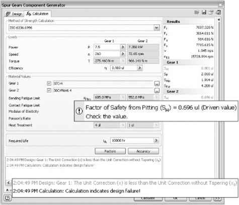
You will notice that you exceed the safety factors for pitting and tooth breakage, as shown in Figure 11.27. To avoid breakage, you can make your gears stronger by making them wider.
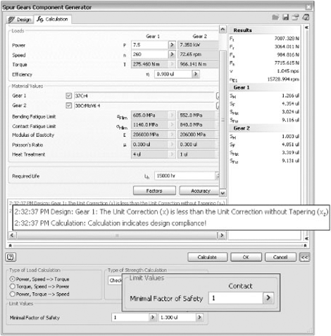
On the Design tab, change the face width of Gear 1 to 60mm and the face width of Gear 2 to 58mm.
In the Advanced Options of the Calculation tab (click the >> button to access these options), change the Contact Safety Factor value of 1.2 to a less cautious factor of 1.0 and click the Calculation button to see if this design complies as indicated in Figure 11.28. You can then click OK to build the gears.
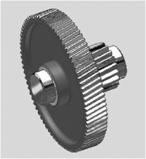
Optionally you can finish off the Gear 1 by adding a couple of cylindrical extrusions and chamfers to the Spur Gear 1 part so that it fits nicely between the two ball bearings. You can also make a 60mm hole in Gear 4 so that it can slide over the shaft of Gear 1. Figure 11.29 shows the smaller Gear 1, while Gear 4 has been made invisible.
Gear design in Inventor is limited to one pair of gears at a time. When designing a gear train of five helical gears, you will have to perform three different gear set calculations and make sure you use the same units in each set.
Flexibility is turned on by default if you specify the Cylindrical Faces when the gear subassembly is designed. If you create the gears before you design the shafts or housing, then the gears are not marked flexible when you place them. If you want the gears to rotate, you can right-click on the subassembly in the browser and select Flexible.
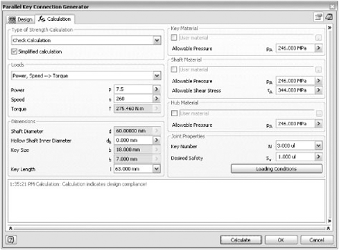
The Key Connection and Spline Connection generators are typically used to fasten gears on shafts. In the previous example, you constructed a spur gear set, but the movement of the spur gear set is not yet driven or connected to the other gears. Therefore, you will use keys to make a rigid connection between Spur Gear 1 and Gear 4 of Gear Set 2 while trying to solve your design challenge. To do this, connect the gear on the shaft with a key connection, and make sure that the connection does not break for a given speed (260rpm) and given power transmission (7.5kW).
Follow these steps using the Key Connection Generator:
On the Get Started tab, click the Open button.
Browse for the file named
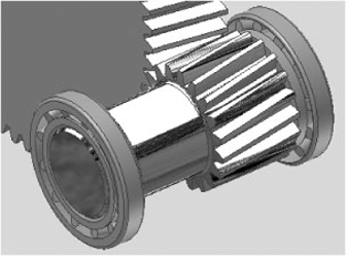
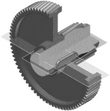
mi_11a_007.iamlocated in the Chapter 11 directory of the Mastering Inventor 2010 folder, and click Open.Activate the view representation called Gears. Make Gear Set:2 and Spur Gear:1 flexible by right-clicking on them in the browser and selecting Flexible. Verify that you can freely rotate Gear 1 around the axis of the bore hole in Gear 4. Figure 11.30 shows Gear 1 and Gear 4.
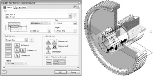
Start the Key Connection Generator from the Power Transmission panel on the Design tab. In the Key area, confirm that the default key type is ISO 2491A. If another key type is selected, click in the field to display the list of keys from Content Center. Change No: Of Keys from 1 to 3.
In the Shaft Groove area, confirm that the Groove With Rounded Ends type is selected. Select the Red cylindrical face of Gear 1 as Reference 1 and the Green end face of Gear 1 as Reference 2. A preview of the keys display on the model.
In the Hub Groove area, select the Blue face of Gear 4 as Reference 1 and any circular edge of Gear 4 as Reference 2.
Based on these selections, the Key Connection Generator updates with an 18mm × 7mm × 50mm key. We need a 63mm long key, which can be selected from the drop-down list in the Key area. Only valid lengths from Content Center are displayed.
In the Select Objects To Generate area, confirm that the Key, Shaft Groove, and Hub Groove buttons are selected. Depending on your parts, the shaft or the gear may already have a groove.
The Key Connection Generator selects an orientation based on the shaft. If you want a specific orientation, select a work plane on the shaft or gear. You can only select planes in the components or in their parent assemblies. No other planes can be selected.
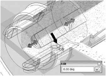
You can change the angle of the first key relative to the orientation plane by dragging the red single-sided arrow, or by double-clicking on it and entering a value, as shown in Figure 11.31.
Your design dialog box should now look like in Figure 11.32.
Before you click OK to generate the keys, you want to make sure that your design withstands the speed (260rpm) and power (7.5kW) you set forth. Enter the speed and power in their respective fields, and select surface-hardened steel for the key material. Leave the loading conditions at their default values in the Joint Properties panel. When you run the calculation, your design is considered to be safe, according to Figure 11.33.
Figure 11.34 shows a cross section of the completed key connection.
The Shaft Generator has a different workflow than other generators. A shaft is designed by adding sections together to come up with the final shaft. You can build a shaft independently, or you can select references in the model to help define the sizes of the sections. This workflow parallels shaft functionality. Each section of a shaft serves a purpose, whether it is locating a bearing or supporting a load.
The design challenge here is to design a shaft that holds the output gear so that it withstands the forces and bending moments generated by the driving gear while lifting a load of 2 tons (20kN).
Follow these steps to design the shaft:
On the Get Started tab, click the Open button.
Browse for the file named
mi_11a_009.iamlocated in the Chapter 11 directory of the Mastering Inventor 2010 folder, and click Open.Start the Shaft Generator from the Power Transmission panel of the Design tab, and click in the graphics window to temporarily place the shaft.
The four buttons in the Placement section specify the exact location of the shaft. If the shaft is the first component, you can skip the precise placement. For this example, click the first button and select a cylindrical surface (such as one of the yellow ones) to define the axis. The next button is automatically enabled, and you select an inside surface to define the start of the shaft (such as the Green face).
Next, select the work plane to define the orientation. If the shaft preview extends outside the housing, click the Flip Side button.
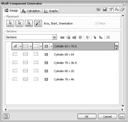
The default shaft consists of four sections. Delete the first three sections by clicking on the section, either in the list or in the graphics window, and clicking the X icon on the right side of the segment. Your assembly should look like Figure 11.35.
Two sets of arrows are now visible on the shaft. The thin RGB arrows on the shaft depict the X, Y, and Z directions as usual and cannot be dragged. The thicker arrows, however, can be dragged.
Dragging the thick double-sided red arrow changes the length of the active shaft segment, and dragging the red dots allows you to change the diameter (in Figure 11.35, above, the first segment is active). You can also enter the diameter and length values manually by clicking the...icon (or double-clicking the segment row in the dialog box), and collect the dimensions by measuring the surrounding geometry.
Dragging the thick blue arrow allows you to change the orientation of the shaft. Dragging the thick green arrow offsets the end of the shaft from the housing. Note that by default the Mate icon is checked, indicating that the shaft will be constrained to the housing.
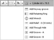
Every segment has four sets of drop-down icons. The second set defines the overall shape of the segment, and the other icons add detail such as chamfers, fillets, grooves, reliefs, wrench flats, threads, and keyways. Figure 11.36 shows the fourth drop-down set.
In these steps, we will create the shaft segments:
Double-click the green arrow at the end of the shaft and set the offset to 0.5mm.
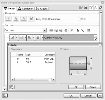
Change the size of the first segment to 60mm × 78.5mm, as shown in Figure 11.37. You can double-click the segment field to display a dialog box or you can use the controls in the graphics window. Add a 0.5mm chamfer to the segment by using the first set of drop-down icons.
Add four more cylindrical segments to the shaft to accommodate the future bearings and the output gear. Right-click below the section and select Sections

68mm × 64mm
75mm × 36.5mm
80mm × 20mm
78mm × 46mm
You have now created the geometry of the shaft so that it fits nicely within the confines of the gearbox, but does it also satisfy the load requirements?
To find out the forces and moments that are at play on the output gear, click OK in the Shaft Generator and create the shaft.
Right-click on the Spur Gears subassembly and choose Edit Using Design Accelerator. Click the Enables/Disables Calculation button (in the top-right corner of the dialog box) to enable the Calculation tab on the Spur Gears component.
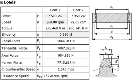
Click the Calculate button and consult the calculation results by clicking the Results button on the Calculation tab. From the results (shown in Figure 11.39), you learn that the radial force on the shaft on the output gear location is 3064N, the tangential force is 7007N, and the axial force is 984N.

Now that you know the forces, you can start the shaft calculation:
Right click on the shaft in the browser or graphics window and select Edit Using Design Accelerator. Click the Calculation tab and select the green dot in the middle of section 2 in the 2D preview or in the graphics window.
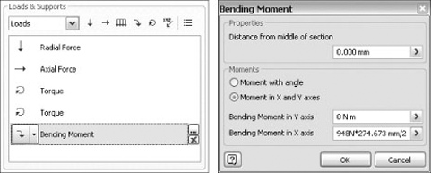
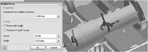
Select Loads from the Loads/Support drop-down list. The available load types are shown in Figure 11.40; they are radial force, axial force, continuous load, bending moment, torque, and common load. Select the down arrow, which is the first load icon.
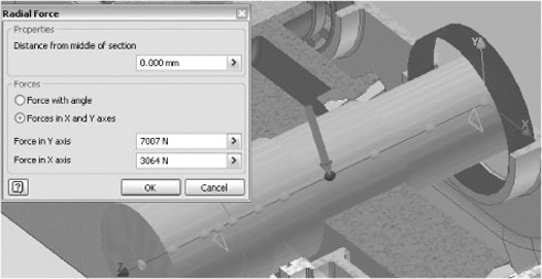
The radial force on the gear translates into a force in the X direction on the shaft. Likewise, the tangential force on the gear will result in a force in the Y direction on the shaft situated in the center of segment 2, which is the segment on which the output gear will sit. By clicking the ...button on the force in the dialog box or by double-clicking the force arrow in the graphics window, you can change the Forces option to Forces in X and Y Axes.
Enter the Force in X axis = 3064N and the Force in Y axis = 7007N. See also Figure 11.41. You can now delete the default radial force on segment 1.
Here are a couple of tips for navigating around the shaft preview. The force arrow can be dragged along the shaft so that it snaps to one of the green hotspots. The green hotspots depict the center and the extremities of the segments and are associative to any shaft geometry change. The blue hotspot depicts the active hotspot (any load or support that is added will be added to the active hotspot). So, it is extremely important to position your blue dot in the right location prior to adding loads or supports!
The force arrows can be reconnected to the green hotspots by double-clicking the arrow and entering a zero distance. When you hold down the Ctrl key, you can rotate the force vector to change its angle.
Next, we add the rest of the forces.
Add a −94 8N axial force to the center of section 2.
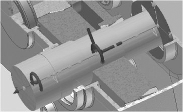
Add a torque of 966Nm to section 2 and a torque of −966Nm to section 5. The torques must be equal and opposite, so the torque value for section 5 is preset to −966Nm. Torque is shown with two circular arrow glyphs that are pointing in opposite directions as illustrated in Figure 11.42.
The shaft will also undergo some bending because of the axial force on the output gear. Determining the value of the bending moment is relatively simple:

The value of the pitch diameter can be found once again in the gear calculation results table (274.673mm) of Figure 11.40.
Enter a bending moment value along the x-axis of 948N*274.673mm/2 on segment 2, as shown in Figure 11.43.
Finally, you add to segment 5 the actual load that the shaft will have to provide (20kN). The load is shown as the arrow on the left pointing down in Figure 11.44.
Select Supports from the Loads/Support drop-down list. Double-click the Free support and change the offset to 10mm. Select the hotspot in the middle of section 4 and add a Fixed support. Delete the default Fixed support.
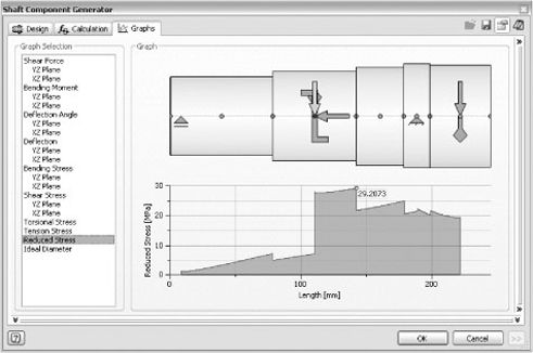
To complete this exercise, inspect several types of graphs on the Graphs tab to see whether stresses remain within reasonable limits. With a 29.2MPa total stress, as shown in Figure 11.45, this design is considered to be safe.
Inventor has a Linear Cam Generator, a Disc Cam Generator, and a Cylindrical Cam Generator. For the benefit of this exercise, we will use the Disc Cam Generator only.
The challenge in this exercise is to design the camshaft of a four-stroke gas engine: design a camshaft that opens the inlet (and outlet valve) over a distance of 0.7mm during ¼ of the full-cycle period. The engine runs at 1000rpm.
Before you dive into the cam design, we'll point out several important things you need to know about the cam generator:
The updates in the Design tab window are not automatic. You will have to click the Calculate button to update the graph after a change has been made.
When hovering over the graph, the tool tip will give intermediate values.
By default there are two segments in the cam graph. You can add segments by clicking the Add Before or Add After button. Click the Delete button to delete segments. You are not editing all segments all the time. The segment number that is shown in the Actual Segment drop-down is the active segment. All edits will affect only the active or actual segment.
The YZ origin plane of the Disc Cam component corresponds with the 0-degree angle of the graph. This is important to know when you later in the design add Angular constraints to this YZ plane to correctly orient the cam on the shaft.
The start plane of the cam is the plane in which the cam profile sketch is created. The generator extrudes the sketch perpendicular to this start plane to obtain the cam.
In the cam dialog box, you can superpose multiple graphs (torque, pressure, and so on). Figure 11.46 shows the icons for the different graph types. Each graph has its own color. For a disc cam, the x-axis of the graph goes from 0 to 360 degrees. For a linear cam, the x-axis represents the length. The vertical axis has no units because all the different cam parameters can be displayed simultaneously on the same graph. This would otherwise result in a ton of different units on the same axis.
Now let's return to our exercise. To work correctly during the four phases of the Otto cycle, ideally our valves would have to work according to the diagram in Figure 11.47.
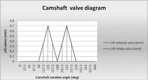
The question is how to follow this ideal diagram as closely as possible within the laws of physics. That is where the Inventor's Disc Cam Generator comes in handy.
On the Get Started tab, click Open.
Browse for the file named
mi_11a_011.iamin the Chapter 11 folder.Start the Disc Cam Generator from the Power Transmission panel of the Design tab.
Click the Cylindrical Face button and select the (red) camshaft.
Click the Start Plane button and select the side of the first raised section on the shaft. Note that because the assembly is sectioned you need to select the face on the un-sectioned side. In this case you can also select the Yellow face of the engine case, as both are in the same plane.
In the Cam area, enter 2.15mm for Basic Radius and 2mm for Cam Width.
In the Follower area, enter 0.5mm for Roller Radius and 0.4mm for Roller Width.
The cam angle vs. lift data is entered in the Actual Segment area. You select the particular segment from the drop-down list at the top of the area, and enter the data.
Confirm that the Actual Segment drop-down is set to segment 1. This segment is part of the base radius, so we are going to set Lift At End to 0.00mm.
Change the drop-down list to segment 2. This segment continues the base radius, so we are going to leave the end height at 0.00mm.
Click Add After to create a new segment 3. This segment will transition from zero to maximum lift. Instead of using the linear transition shown in Figure 11.48, we are going to set Motion Function to Harmonic (sinusoidal). Set Motion End Position to 225 degrees, and Lift At End to 0.7mm.
Click Add After to create a new segment 4. This segment will transition from maximum to zero lift. Confirm Motion Function is set to Harmonic Sinusoidal. Set Motion End Position to 270 degrees, and Lift At End to 0.00mm.
Change the drop-down to segment 5. Confirm that Motion End is 360 degrees and Lift At End is 0.00mm.
You can also overlay other graphs like acceleration and torque over the inlet cam shape graph, as shown in Figure 11.49.
A full overview of all calculations and all graphs can be obtained by exporting the results into an HTML-formatted report by clicking the Results icon in the top-right corner.
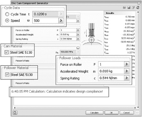
Click the Calculation tab.
The camshaft rotates at half the crankshaft speed, so 1000/2 = 500rpm. In the Cycle Data area, confirm that Speed is selected and enter 500rpm.
In the Follower Loads area, enter 1N as the Force On Roller. Confirm that the Accelerated Weight is 0.01kg. Enter 0.544N/mm for Spring Rating, or spring constant k. Both the spring force and spring constant will be calculated in the next section of the chapter.
Set Cam Material and Follower Material to Steel SAE 5130. This material has an allowable pressure of 900MPa, which is 50% higher than the calculated maximum pressure.
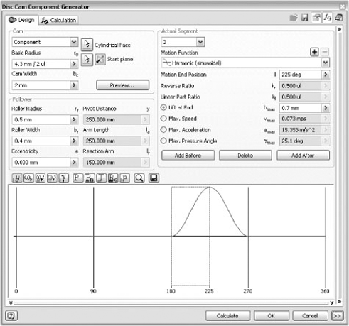
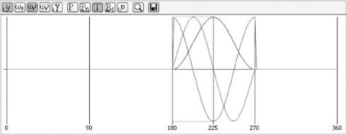
Figure 11.50 shows the calculation values and results.
You could easily copy the Inlet cam and rename the copy to Exhaust Cam, but you would not have any Design Accelerator edit capability on the copy. An alternative and far better method is to use Design Accelerator templates. Most Design Accelerators have a Save icon at the top of the dialog box, and this allows you to create a template file. This is a small file in XML format that allows the reuse of all design and calculation parameters of a previous calculation in subsequent calculations.
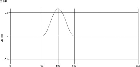
You export the Inlet cam parameters in a file called harmonic.xml and start a new Cam Component Generator dialog box. In this dialog box, you import the harmonic.xml template (use the icon that looks like an open folder), remove the first segment, and reduce the angles of the remaining segments with 90 degrees. Figure 11.51 shows the completed lift graph of the exhaust cam.
When the piston is placed at its top position (ignition), the two cams are mounted and oriented on the shaft in the position, as shown in Figure 11.52. Use Angular Mate constraints between the origin planes of the two cams, and then between the origin plane of one of the cams and the origin plane of the shaft to accomplish the correct 90-degree angular shift between the inlet cam and exhaust cam so that the intake phase correctly follows the exhaust phase. This might require some experimentation. You can simulate the entire Otto cycle by opening the file called mi_11a_077.iam and driving the constraint called Drive Me found by expanding the Origin folder of the top-level assembly. If you have problems finding the right constraints, use the Modeling view mode in the assembly browser to group them.
Inventor can generate four spring types:
Compression springs
Extension springs
Torsion springs
Belleville springs
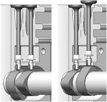
We will illustrate how to use compression springs to generate the springs that allow you to keep the valves closed. For this exercise, you will use a single cylinder four-stroke engine assembly similar to the previous exercise.
Click Open on the Get Started tab.
Browse to the file called
mi_11a_012.iamin the Chapter 11 folder.The browser is set to Modeling view, so all of the constraints are in a folder at the top of the browser instead of being nested under the components. Find the Drive Me constraint and confirm that the value is 0.0 degrees.
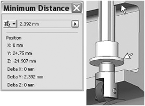
Measure the distance between the Red face on the valve bushing and the Blue face on the crankcase. The result, shown in Figure 11.53, is the minimum working load length of the spring.
Start the Compression Spring Generator from the Spring panel on the Design tab.
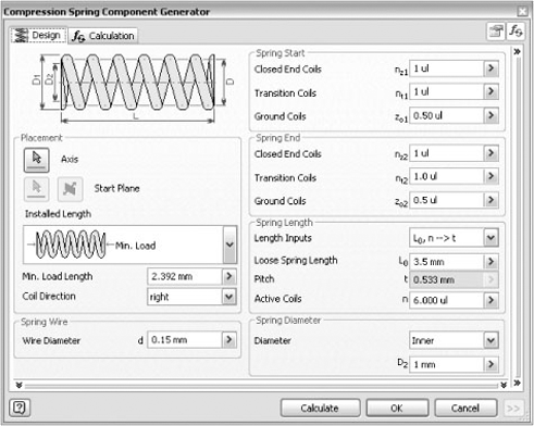
In the Placement area, click the Axis button and select the valve stem. The Start Plane button is automatically enabled, so select the Red face of the valve bushing. A preview is displayed, but the default spring values are much too large for this application.
Confirm that Installed Length is set to Min. Load.
In the Spring Wire area, set Wire Diameter to 0.15mm.
In the Spring Start and Spring End areas, set Closed End Coils to 1, Transition Coils to 1, and Ground Coils to 0.5.
In the Spring Length area, confirm that Length Inputs is set to L0, n → t. Enter 3.5mm for Loose Spring Length, which is considerably larger than the Minimum Working Load Length value of 2.392mm, so the spring preload will keep the valve seated. Enter 6 for the number of active coils.
In the Spring Diameter area, set Diameter to Inner and enter 1mm. The geometric inputs are shown in Figure 11.54.
If you clicked Calculate, you would get impossible values for the minimum load length or pitch. This is because you did not define all load conditions yet, and so far, you have no idea if the spring you are designing meets the requirements for forces and stresses. To determine this, you will enter the working conditions for the spring on the Calculation tab.
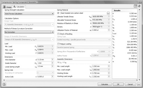
Click the Calculation tab. In the Spring Strength Calculation area, select Work Forces Calculation from the drop-down list.
The spring dimensions are carried over from the Design tab, so you just need to enter the working dimensions for the spring. In the Assembly Dimensions area, select H, L1 → L8 from the drop-down list. The Min. Load Length is carried over from the Design tab. Enter 0.7mm, the cam lift, for the Working Stroke value. Enter a nominal value of 2.39mm for the Working Load Length value.
In the Spring Material area, select Heat Treated Wire Carbon Steel.
Click Calculate. If you look at the calculation results in Figure 11.55, you will see that the Max. Load is .984N, which is satisfactory for this design, and the maximum torsional stress, τ8, of 854MPa is less than the material limit of 972 MPa.
Click OK to create the spring.
The Spring Generator automatically adds a Mate constraint between the spring axis and the inlet valve axis. You can now view the spring as it will be when the valve is open and closed by editing the spring and changing the Installed Length setting from Min. Load to Max. Load. You finally make a copy of the spring so that you can put the copy around the outlet valve. This concludes the compression spring design. Figure 11.56 shows both valve springs, one set at the minimum load and the other at the maximum load.

- Use Inventor's Design Accelerators
Design Accelerators and Design Generators allow you to rapidly create complex geometry and the associated calculations that verify the viability of your design.
- Master It
Your design needs a bolted connection, but you are not certain about the number of bolts to use to ensure a proper connection.
- Use Inventor's Design Calculators
Design Calculators do not create any geometry, but they permit you to store the calculations in the assembly and repeat the calculation with different input values at a later time.
- Master It
You need to calculate the size of a weld between two plates to withstand a certain lateral force.
- Understand the interaction of these tools with Content Center
Some of the generators use content center, while others create custom geometry.
- Master It
You receive an error when you try to specify fasteners for a Bolted Connection.
- Develop best practices for using these tools
In this chapter, we explained how to use Design Accelerators in the best possible way by providing best practices and tips and tricks concerning the use of templates, exploring the benefits of using a particular type of calculation or connection method for a given scenario, and showing how to select the right material to do the job.
- Master It
You need to design a camshaft to activate an inlet valve that needs to respect a specific lift-over-time graph. You also want to reuse the design and slightly modify it for other similar cams like the exhaust valve.
- Master It
You want to design a compression spring that operates within very strict dimensional limitations and find a spring material that also satisfies the load requirements.
- Master It
Your design needs a gear transmission between two shafts with a predefined position, and you want the gears to be separate components that need to be connected to the shaft.