Chapter 5
Keeping Track of Layers and Blocks
Imagine a filing system that has only one category into which you put all your records. For only a handful of documents, such a filing system might work. However, as soon as you start to accumulate more documents, you would want to start separating them into meaningful categories, perhaps alphabetically or by their use, so you could find them more easily.
The same is true for drawings. If you have a simple drawing with only a few objects, you can get by without using layers. But as soon as your drawing gets the least bit complicated, you’ll want to start sorting your objects into layers to keep track of what’s what. Layers don’t restrict you when you’re editing objects such as blocks or groups, and you can set up layers so that you can easily identify which object belongs to which layer.
In this chapter, you’ll learn how to create and use layers to keep your drawings organized. You’ll learn how color can play an important role while you’re working with layers, and you’ll also learn how to include linetypes such as dashes and center lines through the use of layers.
In this chapter, you will learn to:
- Organize information with layers
- Control layer visibility
- Keep track of blocks and layers
Organizing Information with Layers
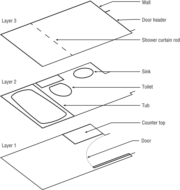
You can think of layers as overlays on which you keep various types of information (see Figure 5-1). In a floor plan of a building, for example, you want to keep the walls, ceiling, plumbing fixtures, wiring, and furniture separate so that you can display or plot them individually or combine them in different ways. It’s also a good idea to keep notes and reference symbols, as well as the drawing’s dimensions, on their own layers. As your drawing becomes more complex, you can turn the various layers on and off to allow easier display and modification.
For example, one of your consultants might need a plot of just the dimensions and walls, without all the other information; another consultant might need only a furniture layout. In the days of manual drafting, you would have had to redraw your plan for each consultant or use overlay drafting techniques, which could be cumbersome. With the AutoCAD® 2014 software, you can turn off the layers you don’t need and plot a drawing containing only the required information. A carefully planned layering scheme helps you produce a document that combines the types of information needed in each case.
Using layers also lets you modify your drawings more easily. For example, suppose you have an architectural drawing with separate layers for the walls, the ceiling plan, and the floor plan. If any change occurs in the wall locations, you can turn on the ceiling plan layer to see where the new wall locations will affect the ceiling, make the proper adjustments, and then turn it off again to see the walls more clearly.
AutoCAD allows an unlimited number of layers, and you can name each layer anything you want, using any characters, with the exception of these: < > / " : ; ? * | , = '.
Creating and Assigning Layers
You’ll start your exploration of layers by using a palette to create a new layer, giving your layer a name, and assigning it a color. Then you’ll look at alternate ways of creating a layer through the command line. Next you’ll assign the new layer to the objects in your drawing. Start by getting familiar with the Layer Properties Manager:
1. Open the Bath file you created in Chapter 4, “Organizing Objects with Blocks and Groups.” (If you didn’t create one, use either 04b-bath.dwg or 04b-bath-metric.dwg.)
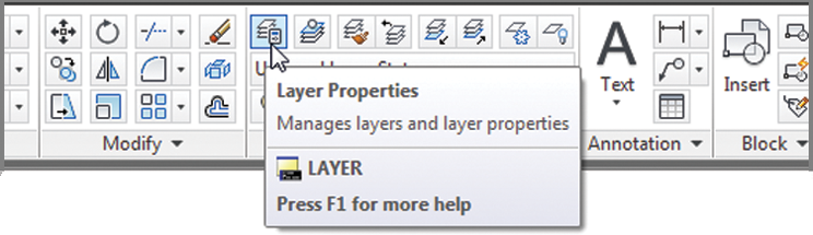
2. To display the Layer Properties Manager, click the Layer Properties tool in the Home tab’s Layers panel, or type LA↵ to use the keyboard shortcut.
The Layer Properties Manager shows you, at a glance, the status of your layers. Right now, you have only one layer, but as your work expands, so too will the number of layers. You’ll then find this palette indispensable.
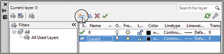
3. Click the New Layer button at the top of the palette. The button has an icon that looks like a star next to a sheet.
A new layer named Layer1 appears in the list box. Notice that the name is highlighted. This tells you that, by typing, you can change the default name to something better suited to your needs.
4. Type Wall. As you type, your entry replaces the Layer1 name in the list box.
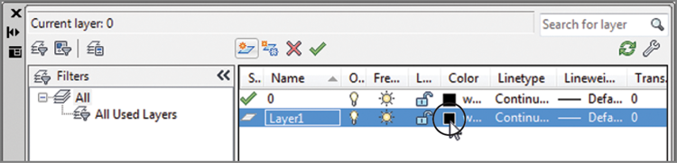
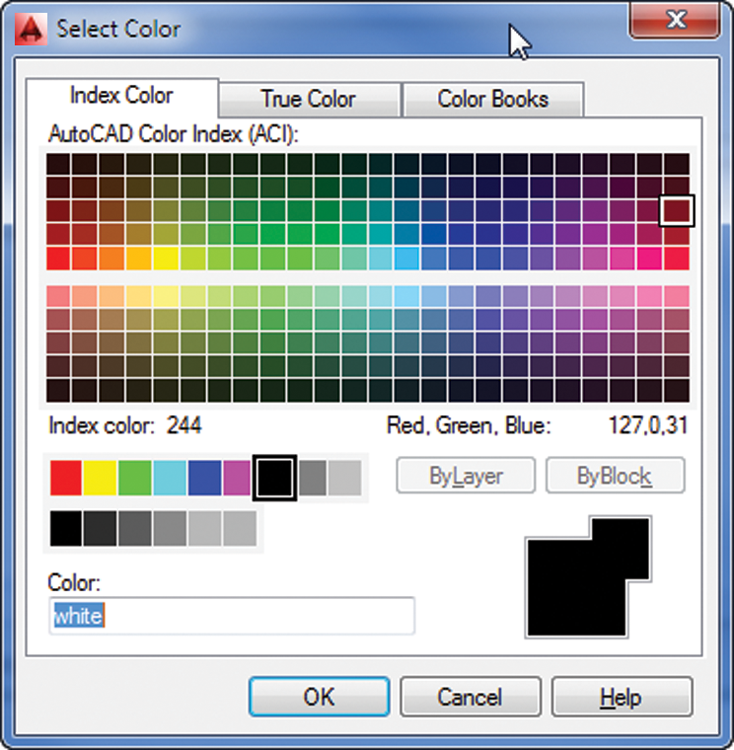
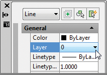
5. With the Wall layer name highlighted, click the Color icon in the Wall layer listing to display a dialog box in which you can assign a color to the Wall layer. You will find the Color icon under the Color column; it currently shows White as its value. The icon is just to the left of the word white, which doesn’t appear in its entirety in the following image.
The Select Color dialog box opens (see
Figure 5-2).
6. In the row of standard colors next to the ByLayer button, click the green square and then click OK. Notice that the color swatch in the Wall layer listing is now green.
7. Click the X at the top of the Layer Properties Manager’s title bar to close it.
From this point on, any object assigned to the Wall layer will appear green, unless the object is specifically assigned a different color.
Using Auto-Hide with the Layer Properties Manager
The Layer Properties Manager is a non-modal (or modeless) palette, which means that any change you make within the palette will take effect immediately in the drawing. It also means that the palette can stay open even while you perform other operations that aren’t layer related. Throughout this chapter, we’ll ask you to open or close the Layer Properties Manager, but if you prefer, you can keep it open all the time. If you decide to keep it open, you may want to use the palette’s Auto-Hide feature. Click the Auto-Hide icon toward the top of the palette’s title bar so that it changes to a single-sided arrowhead.
With Auto-Hide on, the palette will minimize to display only its title bar. To open the palette, click the title bar. To minimize it, point the cursor anywhere outside the palette for a moment. You can also force the palette to the left or right margin of the AutoCAD window. To do this, right-click the palette title bar and select Anchor Left or Anchor Right.
Using True or PANTONE Colors
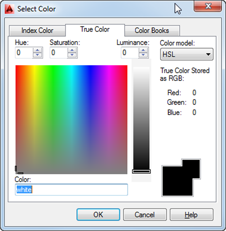
In the preceding exercise, you chose a color from the Index Color tab of the Select Color dialog box. Most of the time, you’ll find that the Index Color tab includes enough colors to suit your needs. But if you’re creating a presentation drawing in which color selection is important, you can choose colors from either the True Color or the Color Books tab of the Select Color dialog box.
The True Color tab offers a full range of colors through a color palette similar to the one found in Adobe Photoshop and other image-editing programs (see Figure 5-3).
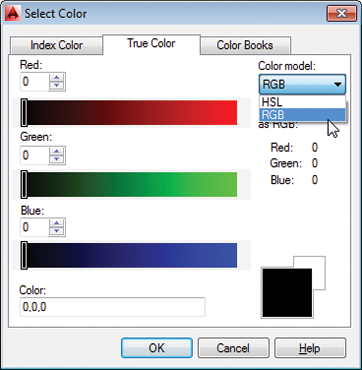
You have the choice of using hue, saturation, and luminance, which is the HSL color model, or you can use the RGB (red, green, blue) color model. You can select HSL or RGB from the Color Model drop-down list in the upper-right corner of the dialog box (see Figure 5-4).
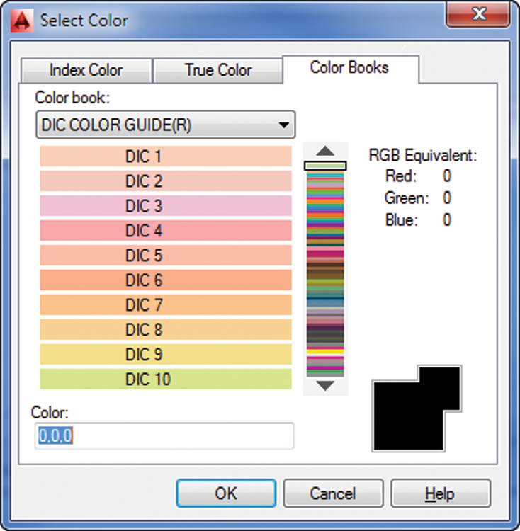
You can also select from DIC, PANTONE, and RAL color books, to match those widely used print color systems, by using the Color Books tab (see Figure 5-5).
Let’s continue with our look at layers in AutoCAD.
Understanding the Layer Properties Manager Palette
The Layer Properties Manager conforms to the Windows interface standard. The most prominent feature of this palette is the layer list box, as you saw in the previous exercise. Notice that the bar at the top of the list of layers offers several columns for the various layer properties. Just as in Windows Explorer, you can adjust the width of each column in the list of layers by clicking and dragging either side of the column headings. You can also sort the layer list based on one of these properties by clicking the property name at the top of the list. Also, just as with other Windows list boxes, you can Shift+click to select a block of layer names, or you can Ctrl+click individual names to select multiple layers throughout the list. These features will become helpful as your list of layers grows.
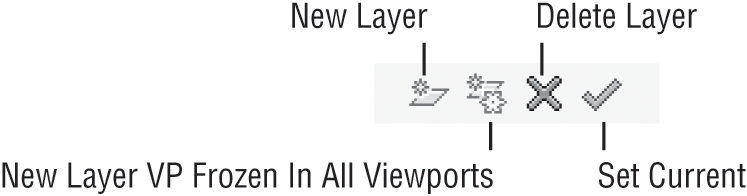
Above the layer list, you can see four tool buttons.
You’ve already seen how the New Layer tool works. The tool next to the New Layer tool, New Layer VP Frozen In All Viewports, looks similar to the New Layer tool and performs a similar function. The main difference is that the New Layer VP Frozen In All Viewports tool freezes the newly created layer. To delete layers, you select a layer or group of layers and then click the Delete Layer tool. Be aware that you can’t delete layer 0, locked layers, or layers that contain objects. The Set Current tool enables you to set the current layer, the one on which you want to work. You can also see at a glance which layer is current by the green check mark in the Status column of the layer list.
Another way to create or delete layers is to select a layer or set of layers from the list box and then right-click. A menu appears, which includes the same functions as the tools above the layer list.
You’ll also notice another set of three tools farther to the left of the New Layer tool. Those tools offer features to organize your layers in a meaningful way. You’ll get a closer look at them a little later in this chapter in the section “Taming an Unwieldy List of Layers.”
Controlling Layers through the Layer Command
You’ve seen how the Layer Properties Manager makes it easy to view and edit layer information and how you can select layer colors from the Select Color dialog box. But you can also control layers through the Command prompt.
Use these steps to control layers via the Command prompt:
1. Press the Esc key to make sure any current command is canceled.
2. At the Command prompt, enter -
Layer↵. Make sure you include the hyphen in front of the word
Layer. The following prompt appears:
Enter an option
[?/Make/Set/New/Rename/ON/OFF/Color/Ltype/
LWeight/TRansparency/MATerial/VStyle/
Plot/ Freeze/Thaw/LOck/Unlock/stAte/
Description/rEconcile]:
You’ll learn about many of the options in this prompt as you work through this chapter.
3. Enter N↵ to select the New option.
4. At the Enter name list for new layer(s): prompt, enter Wall2↵. The [?/Make/Set/New/Rename/ON/OFF/Color/Ltype/LWeight/TRansparency/MATerial/Plot/PStyle/Freeze/Thaw/LOck/Unlock/stAte/rEconcile]: prompt appears again.
5. Enter C↵.
6. At the New color [Truecolor/COlorbook]: prompt, enter Yellow↵. Or, you can enter 2↵, the numeric equivalent of the color yellow in AutoCAD.
7. At the Enter name list of layer(s) for color 2 (yellow) <0>: prompt, enter Wall2↵. The [?/Make/Set/New/Rename/ON/OFF/Color/Ltype/LWeight/TRansparency/MATerial/Plot/Freeze/Thaw/LOck/Unlock/stAte/rEconcile]: prompt appears again.
8. Press ↵ to exit the Layer command.
Each method of controlling layers has its own advantages. The Layer Properties Manager offers more information about your layers at a glance. On the other hand, the Layer command offers a quick way to control and create layers if you’re in a hurry. Also, if you intend to write custom macros, you’ll want to know how to use the Layer command, as opposed to using the Layer Properties Manager, because palettes can’t be controlled through custom toolbar buttons or scripts.
Assigning Layers to Objects
When you create an object, that object is assigned to the current layer. Until now, only one layer has existed—layer 0—and it contains all the objects you’ve drawn so far. Now that you’ve created some new layers, you can reassign objects to them by using the Properties palette:
1. Select the four lines that represent the bathroom walls. If you have trouble singling out the wall to the left, use a window to select the wall line.
2. With the cursor in the drawing area, right-click and choose Properties from the context menu to open the Properties palette. This palette lets you modify the properties of an object or a set of objects. (See the upcoming sidebar “Understanding Object Properties.”)
3. Click the Layer option on the list in the Properties palette. Notice that an arrow appears in the layer name to the right of the Layer option.
4. Click the down-pointing arrow to the far right of the Layer option to display a list of all the available layers.
5. Select the Wall layer from the list. Notice that the wall lines you selected change to a green color. This tells you that the objects have been assigned to the Wall layer. (Remember that you assigned a green color to the Wall layer.)
6. Close the Properties palette by clicking the X at the top of its title bar.
7. Press the Esc key to clear your selection.
The bathroom walls are now on the new layer called Wall and are green. Layers are more easily distinguished from one another when you use colors to set them apart.
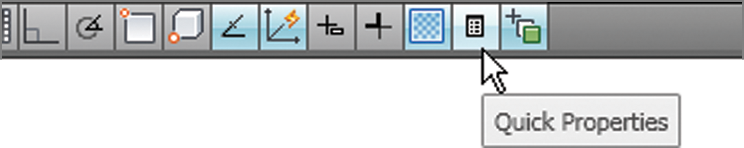
Using the Quick Properties Panel
This chapter focuses on the tools in the Ribbon and the Properties palette to set the properties of an object. You can also use the Quick Properties panel to change the color, layer, and linetype of objects. When the Quick Properties panel is turned on, it appears automatically when you select an object. You can turn it on or off by clicking the Quick Properties tool in the status bar.
Next, you’ll practice the commands you learned in this section and try some new ones by creating new layers and changing the layer assignments of the rest of the objects in your bathroom:

1. Click the Layer Properties tool in the Home tab’s Layers panel to open the Layer Properties Manager. Create a new layer called Fixture, and give it the color blue.
You can change the name of a layer in the Layer Properties Manager. Select the layer name that you want to change and click it again so that the name is highlighted, or press the F2 key. You can then rename the layer. This works in the same way as renaming a file or folder in Windows.
2. Press the Esc key to clear any selections and then click the Tub and Toilet blocks.
3. Right-click and choose Properties from the context menu to open the Properties palette.
4. Click Layer in the list of properties, and then select Fixture from the drop-down list to the right of the layer listing.
5. Click the X at the top of the title bar of the Properties palette to dismiss it, and then press the Esc key to clear your selection.
6. Create a new layer for the door, name the layer Door, and make it red.
7. Just as you’ve done with the walls and fixtures, use the Properties palette to assign the door to the Door layer.
8. Use the Layer Properties Manager to create three more layers, one for the ceiling, one for the doorjambs, and one for the floor. Create these layers, and set their colors as indicated (remember that you can open the Select Color dialog box by clicking the color swatch of the layer listing):
| Ceiling | Magenta (6) |
| Jamb | Green (3) |
| Floor | Cyan (4) |
Understanding Object Properties
It helps to think of the components of an AutoCAD drawing as having properties. For example, a line has geometric properties, such as its length and the coordinates that define its endpoints. An arc has a radius, a center, and beginning and ending coordinates. Even though a layer isn’t an object you can grasp and manipulate, it can have properties such as color, linetypes, and lineweights.
By default, objects take on the color, linetype, and lineweight of the layer to which they’re assigned, but you can also assign these properties directly to individual objects. These general properties can be manipulated through both the Properties palette and the Home tab’s Properties panel.
Although many of the options in the Properties palette may seem cryptic, don’t worry about them at this point. As you work with AutoCAD, these properties will become more familiar. You’ll find that you won’t be too concerned with the geometric properties because you’ll be manipulating them with the standard editing tools in the Modify panel. The other properties will be explained in the rest of this chapter and in other chapters.
In step 3 of the previous exercise, you used the Properties palette, which offered several options for modifying the block. The options displayed in the Properties palette depend on the objects you’ve selected. With only one object selected, AutoCAD displays options that apply specifically to that object. With several objects selected, you’ll see a more limited set of options because AutoCAD can change only those properties that are common to all the objects selected.
Note that in a block, you can change the color assignment and linetype of only those objects that are on layer 0. See the sidebar “Controlling Colors and Linetypes of Blocked Objects” later in this chapter.
Working on Layers
So far, you’ve created layers and then assigned objects to them. In this section, you’ll learn how to use the layer drop-down list in the Layers panel to assign layers to objects. In the process, you’ll make some additions to the drawing.
Controlling Colors and Linetypes of Blocked Objects
Layer 0 has special importance to blocks. When objects assigned to layer 0 are used as parts of a block and that block is inserted on another layer, those objects take on the characteristics of their new layer. However, if those objects are on a layer other than layer 0, they maintain their original layer characteristics even if you insert or change that block to another layer. For example, suppose the tub is drawn on the Door layer instead of on layer 0. If you turn the tub into a block and insert it on the Fixture layer, the objects the tub comprises will maintain their assignment to the Door layer even though the Tub block is assigned to the Fixture layer.
It may help to think of the block function as a clear plastic bag that holds together the objects that make up the tub. The objects inside the bag maintain their assignment to the Door layer even while the bag itself is assigned to the Fixture layer. This concept may be a bit confusing at first, but it should become clearer after you use blocks for a while.
AutoCAD also enables you to have more than one color or linetype on an object. For example, you can use the Color and Linetype drop-down lists in the Properties palette to alter the color or linetype of an object on layer 0. That object then maintains its assigned color and linetype—no matter what its layer assignment. Likewise, objects specifically assigned a color or linetype aren’t affected by their inclusion in blocks.
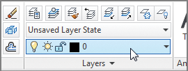
The current layer is still layer 0, and unless you change the current layer, every new object you draw will be on layer 0. Here’s how to change the current layer:
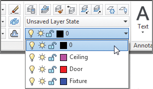
1. Press the Esc key to clear any selections, and then click the layer drop-down list on the Home tab’s Layers panel.
The list shows you all the layers available in the drawing. Notice the icons that appear next to the layer names; they control the status of the layer. You’ll learn how to work with these icons later in this chapter. Also notice the box directly to the left of each layer name. This shows you the color of the corresponding layer.
Momentarily placing the cursor on an icon in the layer drop-down list displays a tool tip that describes the icon’s purpose.
2. Click the Jamb layer name. The drop-down list closes and the name Jamb appears in the panel’s layer name box. Jamb is now the current layer.
You can also use the Layer command to reset the current layer. To do this using the keyboard, enter -Layer↵S↵ and then enter Jamb↵↵.
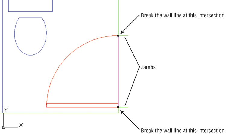
3. Zoom in on the door and draw a 5″ line; start at the lower-right corner of the door, and draw toward the right. Metric users should draw a 13 cm line.
4. Draw a similar line from the top-right end of the arc. Your drawing should look like
Figure 5-6.
Because you assigned the color green to the Jamb layer, on your own screen you’ll see that the two lines you just drew to represent the doorjambs are green. This gives you a visual cue about which layer you’re on as you draw.
Now you’ll use the part of the wall between the jambs as a line representing the door header (the part of the wall above the door). To do this, you’ll have to cut the line into three line segments and then change the layer assignment of the segment between the jambs:
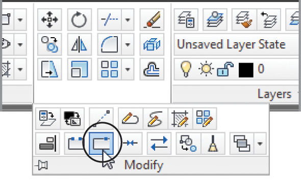
1. Click the Break At Point tool in the Home tab’s expanded Modify panel.
2. At the Select object: prompt, click the wall between the two jambs.
3. At the
Specify first break point: prompt, use the Endpoint osnap override to pick the endpoint of the door’s arc that is touching the wall, as shown previously in
Figure 5-6.
4. Click Break At Point on the expanded Modify panel again, and then repeat steps 2 and 3, this time using the jamb near the door hinge location to locate the break point (see
Figure 5-6).
Although it may not be obvious, you’ve just broken the right-side wall line into three line segments: one at the door opening and two more on either side of the jambs. You can also use the Break tool (below the Break At Point tool) to produce a gap in a line segment.
The Break At Point tool won’t work on a circle. You can, however, use the Break tool to place a small gap in the circle. If you create a small enough gap, the circle will still look like a full circle.
Next you’ll change the Layer property of the line between the two jambs to the Ceiling layer. However, instead of using the Properties palette as you’ve done in earlier exercises, you’ll use a shortcut method:
1. Click the line between the doorjambs to highlight it. Notice that the layer listing in the Layers panel changes to Wall. Whenever you select an object to expose its grips, the Object Color, Linetype, Lineweight, and Plot Style listings in the Properties panel change to reflect those properties of the selected object.
2. Click the layer name in the Layers panel to open the layer drop-down list.
3. Click the Ceiling layer. The list closes and the line you selected changes to the magenta color, showing you that it’s now on the Ceiling layer. Also notice that the Object Color list in the Properties panel changes to reflect the new color for the line.
4. Press the Esc key twice to clear the grip selection. Notice that the layer returns to Jamb, the current layer.
5. Click the Zoom Previous tool from the Zoom flyout in the Navigation bar. You can also enter Z↵P↵.
In this exercise, you saw that when you select an object with no command active, the object’s properties are immediately displayed in the Properties palette under Object Color, Linetype, and Lineweight. Using this method, you can also change an object’s color, linetype, and lineweight independent of its layer. Just as with the Properties palette, you can select multiple objects and change their layers through the layer drop-down list. These options in the Home tab’s Properties panel offer a quick way to edit some of the properties of objects.
Now, you’ll finish the bathroom by adding a sink to a layer named Casework:
1. Open the Layer Properties Manager, and create a new layer called Casework.
2. With the Casework layer selected in the layer list, click the Set Current button at the top of the palette.
3. Click the color swatch for the Casework layer listing, and then select Blue from the Select Color dialog box. Click OK to exit the dialog box.
4. Click X in the Layer Properties Manager palette. Notice that the layer drop-down list in the Layers panel indicates that the current layer is Casework.
Next you’ll add the sink. As you draw, the objects will appear in blue, the color of the Casework layer.
5. Choose Zoom All from the Zoom flyout on the Navigation bar, or type Z↵A↵.
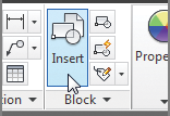
6. Click the Insert tool on the Home tab’s Block panel, and then click the Browse button in the Insert dialog box to open the Select Drawing File dialog box.
7. Locate the sink.dwg file from the companion web page, and double-click it.
8. In the Insert dialog box, make sure the Specify On-Screen options in both the Scale and Rotation groups aren’t selected; then click OK.
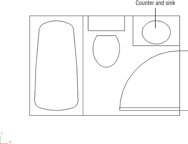
9. Place the sink roughly in the upper-right corner of the bathroom plan, and then use the Move command to place it accurately in the corner, as shown in
Figure 5-7.
Controlling Layer Visibility
We mentioned earlier that you’ll sometimes want to display only certain layers to work within a drawing. In this bathroom is a door header that would normally appear only in a reflected ceiling plan. To turn off a layer so that it becomes invisible, you click the lightbulb icon in the Layer Properties Manager, as shown in these steps:
1. Open the Layer Properties Manager by clicking the Layer Properties tool in the Layers panel.
2. Click the Ceiling layer in the layer list.
3. Click the lightbulb icon in the layer list, next to the Ceiling layer name. The lightbulb icon changes from yellow to gray to indicate that the layer is off.
4. Click the X at the top of the Layer Properties Manager’s title bar to close it. The door header (the line across the door opening) disappears because you’ve made it invisible by turning off its layer.
Getting Multiple Uses from a Drawing Using Layers
Layering lets you use a single AutoCAD drawing for multiple purposes. A single drawing can show both the general layout of the plan and more detailed information such as the equipment layout and the floor-paving layout.
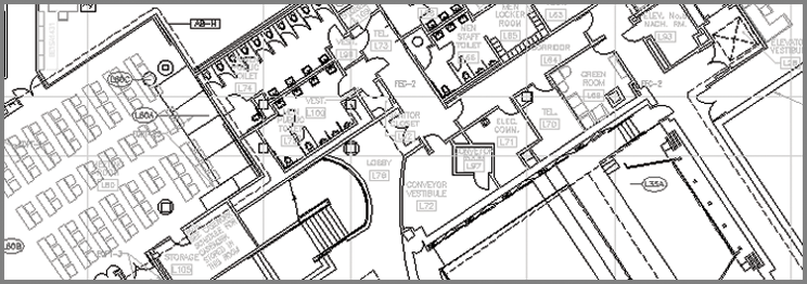
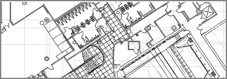
The following two images are reproductions of the San Francisco Main Library’s lower level and show how one floor plan file was used for two purposes. The first view shows the layout of furnishings, and the second view shows a paving layout. In each case, the same floor plan file was used, but in the first panel, the paving information is on a layer that is turned off. Layers also facilitate the use of differing scales in the same drawing. Frequently, a small-scale drawing of an overall plan will contain the same data for an enlarged view of other portions of the plan, such as a stairwell or an elevator core. The detailed information, such as notes and dimensions, might be on a layer that is turned off for the overall plan.
You can also control layer visibility by using the layer drop-down list on the Layers panel:
1. On the Home tab’s Layers panel, click the layer drop-down list.
2. Find the Ceiling layer, and note that its lightbulb icon is gray. This tells you that the layer is off and not visible.
3. Click the lightbulb icon to make it yellow; the door header reappears.
4. Click the drawing area to close the layer drop-down list.
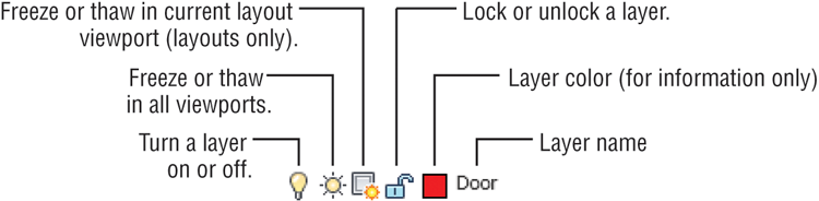
Figure 5-8 explains the roles of the other icons in the layer drop-down list.
When you start to work with layouts in Chapter 8, “Introducing Printing, Plotting, and Layouts,” and Chapter 16, “Laying Out Your Printer Output,” you’ll learn about viewports. A viewport is like a custom view of your drawing. You can have multiple viewports in a layout, each showing a different part of your drawing. Layer properties can be controlled for each viewport independently, so you can set up different linetypes, colors, and layer visibility for each viewport.
Finding the Layers You Want
With only a handful of layers, it’s fairly easy to find the layer you want to turn off. It becomes much more difficult, however, when the number of layers exceeds a couple dozen. The Layer Properties Manager offers some useful tools to help you find the layers you want quickly.
Suppose you have several layers whose names begin with C, such as C-lights, C-header, and C-pattern, and you want to find those layers quickly. You can click the Name button at the top of the layer list to sort the layer names in alphabetic order. (Click the Name button again to reverse the order.) To select those layers for processing, click the first layer name that starts with C, and then scroll down the list until you find the last layer of the group and Shift+click it. All the layers between those layers are selected. If you want to deselect some of those layers, hold down the Ctrl key while clicking the layer names you don’t want to include in your selection. Another option is to Ctrl+click the names of other layers you want selected.
The Color and Linetype headings at the top of the list let you sort the list by virtue of the color or linetype assignments of the layers. Other columns sort the list by virtue of status: On/Off, Freeze/Thaw, Lock/Unlock, and so forth. (See the sidebar “Freeze, Lock, Transparency, and Other Layer Options” later in this chapter.)
Now try changing the layer settings again by turning off all the layers except Wall and Ceiling, leaving just a simple rectangle. In this exercise, you’ll get a chance to experiment with the On/Off options of the Layer Properties Manager:

1. Click the Layer Properties tool in the Layers panel.
2. Click the top layer name in the list box; then Shift+click the last layer name. All the layer names are highlighted.
Another way to select all the layers at once in the Layer Properties Manager is to right-click the layer list and then choose the Select All option from the context menu. If you want to clear your selections, right-click the layer list and choose Clear All.
3. Ctrl+click the Wall and Ceiling layers to deselect them and thus exempt them from your next action.
4. Click the lightbulb icon of any of the highlighted layers.
5. A message appears, asking if you want the current layer on or off. Select “Turn the current layer off” in the message box. The lightbulb icons turn gray to show that the selected layers have been turned off.
6. Close or minimize the Layer Properties Manager. The drawing now appears with only the Wall and Ceiling layers displayed. It looks like a simple rectangle of the room outline.
7. Open the Layer Properties Manager again, select all the layers as you did in step 2, and then click any of the gray lightbulbs to turn on all the layers at once.
8. Click the X at the top of the Layer Properties Manager’s title bar to close it.
In this exercise, you turned off a set of layers by clicking a lightbulb icon. You can freeze/thaw, lock/unlock, or change the color of a group of layers in a similar manner by clicking the appropriate layer property. For example, clicking a color swatch of one of the selected layers opens the Select Color dialog box, in which you can set the color for all the selected layers.
Taming an Unwieldy List of Layers
Chances are you’ll eventually end up with a fairly long list of layers. Managing such a list can become a nightmare, but AutoCAD provides some tools to help you organize layers so you can keep track of them more easily.
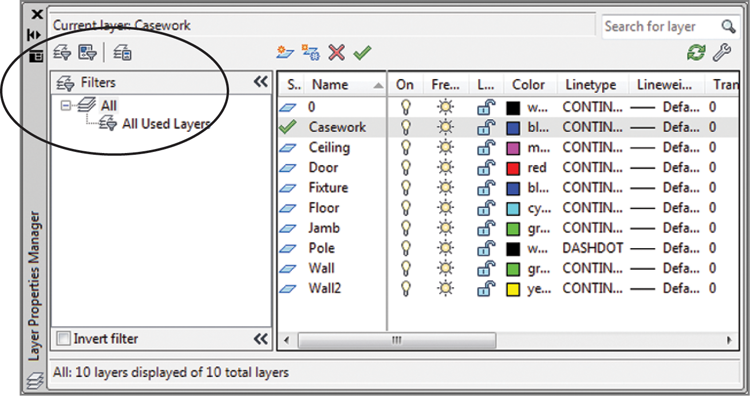
On the left side of the Layer Properties Manager is a set of tools and a list box designed to help you with your layer-management tasks (see Figure 5-9).
In the upper-left corner of the palette is a toolbar with three tools:
The New Property Filter tool lets you filter your list of layers to display only layers with certain properties, such as specific colors or names.
The New Group Filter tool lets you create named groups of layers that can be quickly recalled at any time. This tool is helpful if you often work with specific sets of layers. For example, you might have a set of layers in an architectural drawing that pertains to the electrical layout. You could create a group filter called Electrical that filters out all layers except those pertaining to the electrical layout. The filters don’t affect the layers in any way; they just limit which layers are displayed in the main layer list.
The Layer States Manager tool lets you create sets of layer states. For example, if you want to save the layer settings that have only the Wall and Door layers turned on, you can do so by using this tool.
Freeze, Lock, Transparency, and Other Layer Options
You may have noticed the Freeze and Thaw icons in the Layer Properties Manager. These options are similar to On and Off icons. However, Freeze not only makes layers invisible, it also tells AutoCAD to ignore the contents of those layers when you select the All response at the Select objects: prompt. Freezing layers can save time when you issue a command that regenerates a complex drawing. This is because AutoCAD ignores objects on frozen layers during a drawing regen. You’ll get firsthand experience with Freeze and Thaw in Chapter 7, “Mastering Viewing Tools, Hatches, and External References.”
Another pair of Layer Properties Manager options, Lock and Unlock, offers functionality similar to Freeze and Thaw. If you lock a layer, you can view and snap to objects on that layer, but you can’t edit those objects. This feature is useful when you’re working on a crowded drawing and you don’t want to edit portions of it accidentally. You can lock all the layers except those you intend to edit and then proceed to work without fear of making accidental changes. The expanded Layers Ribbon panel offers a Locked Layer Fading slider that allows you to distinguish locked layers more easily by fading them. The slider does not affect plotter output because it is only a visual aid to use when you are editing your drawings.
Three more options—Lineweight, Plot Style, and Plot—offer control over the appearance of printer or plotter output. Lineweight lets you control the width of lines in a layer. Plot Style lets you assign plotter configurations to specific layers. (You’ll learn more about plot styles in Chapter 9, “Understanding Plot Styles.”) Plot lets you determine whether a layer gets printed in hard-copy output. This can be useful for setting up layers you may use for layout purposes only. The Linetype option lets you control line patterns, such as dashed or center lines.
Transparency enables you to make a layer transparent. You can enter a value from 0, which is completely opaque, to 90, which is the maximum transparency allowed. After setting the transparency value, you may need to enter Re↵ to see the transparency of the layer.
Finally, you can save layer settings for later recall by using the Layer States Manager tool in the upper-left corner of the Layer Properties Manager. This feature is extremely useful when you want to save different layer combinations. Chapter 15, “Advanced Editing and Organizing,” shows you how to use this feature. This option is also accessible from the stAte option in the command-line version of the Layer command.
Filtering Layers by Their Properties
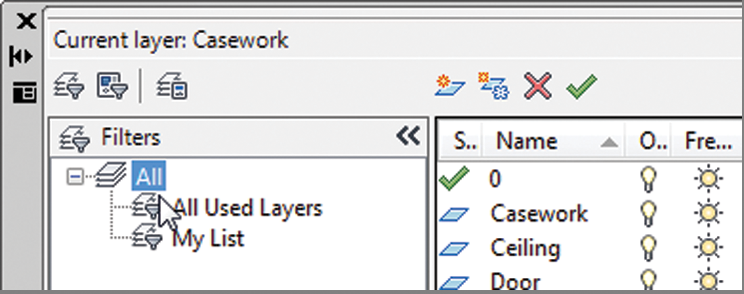
Below the New Property Filter, New Group Filter, and Layer States Manager tools is a filter list, which is a hierarchical list displaying the different sets of layer properties and group filters. Right now, you don’t have any filters in place, so you see only All and All Used Layers.
In this section, you’ll learn how the tools and the filter list box work. You’ll start with a look at the New Property Filter tool:
1. Open the Layer Properties Manager by clicking the Layer Properties tool in the Layers panel.
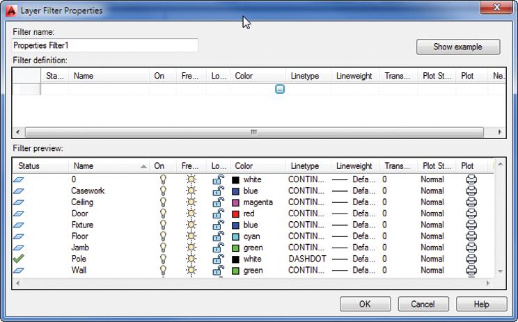
2. Click the New Property Filter tool in the upper-left corner of the Layer Properties Manager to open the Layer Filter Properties dialog box. You see two list boxes. The Filter Definition list box at the top is where you enter your filter criteria. The Filter Preview list box below is a preview of your layer list based on the filter options. Right now, there are no filter options, so the Filter Preview list shows all the layers.
3. In the Filter Definition list box, click the blank box just below the Color label. A button appears in the box (see
Figure 5-10).
4. Click in the blank box again; then enter red↵. The Filter Preview changes to show only layers that are red. In the current drawing, only one layer has been assigned the color red.
5. Click twice in the blank box below the one you just edited. Again, a button appears.
6. This time, enter green↵. The layers that are green appear in the Filter Preview list.
You can also select a color from the Select Color dialog box by clicking the button that appears in the box.
7. In the Filter Definition list, click in the Name column in the third row down. A cursor appears, followed by an asterisk.
8. Type F. Two new layers that have names beginning with F are added to the Filter Preview list.
9. In the Filter Name text box at the upper-left corner of the dialog box, change the name Properties Filter1 to My List, and then click OK.
Now you see the My List filter in the list box on the left side of the Layer Properties Manager.
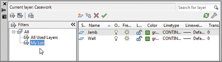
The layer list shows only the layers that have properties conforming to those you selected in the Layer Filter Properties dialog box. Notice that My List is highlighted in the filter list to the left. This tells you that My List is the current layer property filter being applied to the layer list to the right.
You can change the layer list display by selecting different options in the filter list. Try these steps:
1. Click the All option in the filter list at the left side of the dialog box. The layer list to the right changes to display all the layers in the drawing. Also note that a brief description of the current layer filter is displayed at the bottom of the dialog box.
2. Click the All Used Layers option in the filter list. Now all of the layers continue to be displayed.
3. Click My List. The layer list changes back to the limited set of layers from your filter list.
4. Double-click My List. The Layer Filter Properties dialog box opens and displays the list of layer properties you set up earlier for My List. You can edit the criteria for your filter by making modifications in this dialog box.
5. Click Cancel to exit the Layer Filter Properties dialog box.
Creating Layer Groups
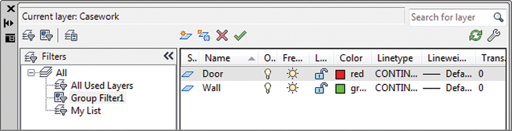
The preceding exercise shows how you can filter out layer names based on the properties you specify in the Layer Filter Properties dialog box. But suppose you want to create a layer filter list by graphically selecting objects on the screen. You can use the New Group Filter tool to do just that:
1. Click the New Group Filter tool in the upper-left corner of the Layer Properties Manager, and then press ↵ to accept the default name for the group. You see a new listing appear called Group Filter1.
2. Right-click the Group Filter1 listing to the left, and then choose Select Layers ⇒ Add from the context menu. Notice that your cursor is now a Pickbox cursor.
3. Click a line representing a wall of the bathroom; then click the door. Press ↵ when you’re finished with your selection. The layers of the two objects you selected are displayed in the layer list. Also note that Group Filter1 is highlighted in the filter list to the left.
You may have noticed the Select Layers ⇒ Replace option in the context menu in step 2. This option lets you completely replace an existing group filter with a new selection set. It works just like the Select Layers ⇒ Add option. You can also click and drag layers from the All layer list to the group filter list name in the left column.
Earlier you saw how you can double-click a properties filter to edit a properties filter list. But group filters work in a slightly different way. If you want to add layers to your group filter, you can click and drag them from the layer list to the group filter name. Here’s how it’s done:
1. In the Layer Properties Manager, select All from the filter list to the left.
2. Click the Fixture layer in the layer list; then Ctrl+click the Jamb layer in the list. These are the layers you’ll add to the Group Filter1 layer group.
3. Click and drag the Fixture and Jamb layers to the Group Filter1 listing in the filter list.
4. To check the addition to Group Filter1, click it in the filter list. The Fixture and Jamb layers have been added to the Group Filter1 list.
If you want to delete a layer from a group filter, you can use the context menu, as shown in these steps:
1. With the Group Filter1 list selected, select the Jamb layer from the layer list and then right-click it.
2. Select Remove From Group Filter from the context menu. (Make sure you don’t select Delete Layer.) Jamb is removed from the Group Filter1 list.
You can also convert a layer property filter into a group filter. Select the layer property filter from the filter list, right-click, and then select Convert To Group Filter. The icon for the layer property filter changes to a group filter icon, indicating that it’s now a group filter.
You’ve seen how you can add property and group filters to the Layer Properties Manager by using the tools on the left side of the palette. One tool you haven’t explored yet is the Layer States Manager. To understand how this tool works, you’ll need to learn a little more about AutoCAD; look for a discussion of the Layer States Manager in Chapter 15.
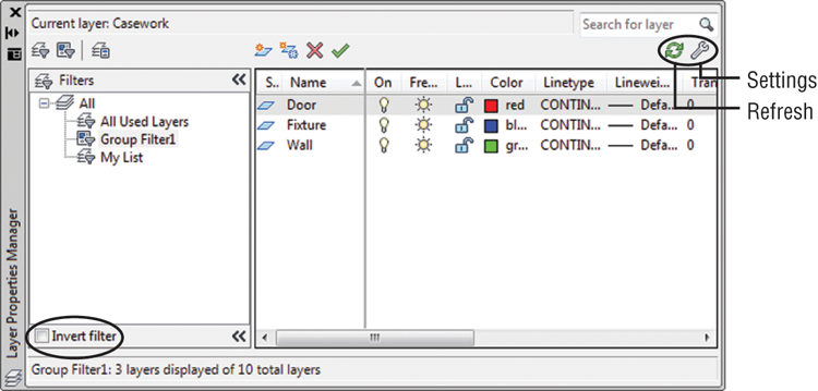
Before you move on, you’ll want to know about a few other options that appear in the Layer Properties Manager (see Figure 5-11):
The Invert Filter check box at the bottom of the Filters list changes the list of layers to show all layers excluding those in the selected filter. For example, if the My List filter contains layers that are red and you select Invert Filter, the layer list will display all layers except those that are red.
The Refresh tool in the upper-right corner updates the layer information in the Layer Properties Manager.
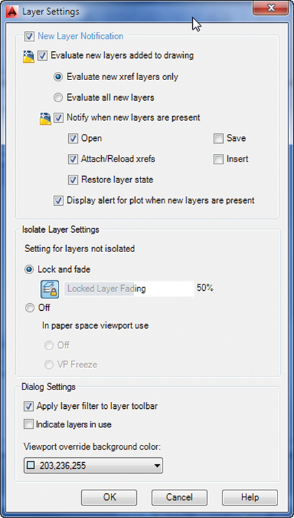
The Settings button in the upper-right corner opens the Layer Settings dialog box. This dialog box controls the way you’re notified when new layers are added to a drawing (see
Figure 5-12).
In the next section, you’ll find some tips for how to use layer names so that you can use text filters more effectively.
Naming Layers to Stay Organized
In the previous section, you saw how to create a layer property filter by using the name of a layer. If you name layers carefully, you can use them as a powerful layer-management tool. For example, suppose you have a drawing whose layer names are set up to help you easily identify floor-plan data versus ceiling-plan data, as in the following list:
- A-FP-WALL-JAMB
- A-FP-WIND-JAMB
- A-CP-WIND-HEAD
- A-CP-DOOR-HEAD
- L-FP-CURB
- C-FP-ELEV
The first character in the layer name designates the discipline related to that layer: A for architectural, L for landscape, and C for civil. In this example, layers with names containing the two characters FP signify floor-plan layers. CP designates ceiling-plan information.
These layer examples are loosely based on a layer-naming convention devised by the American Institute of Architects (AIA). As you can see from this example, careful naming of layers can help you manage them.
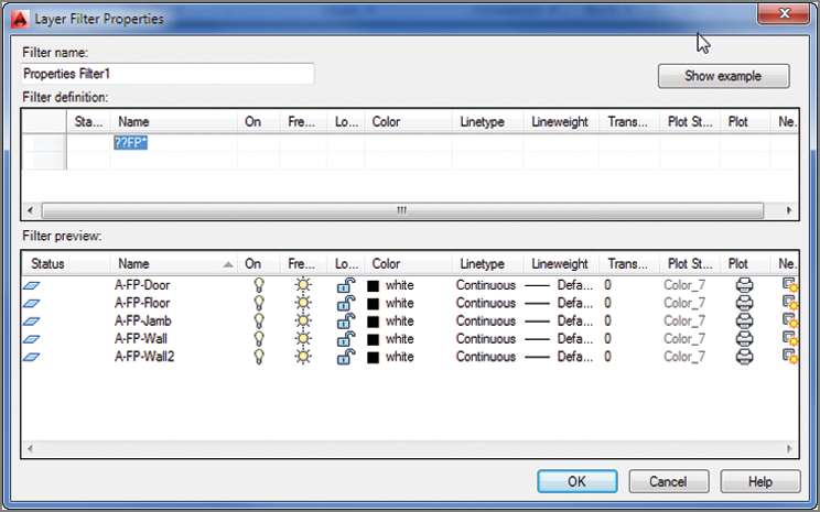
If you want to isolate only those layers that have to do with floor plans, regardless of their discipline, enter ??FP* in the Name column of the Layer Filter Properties dialog box. You can then give this layer property filter the name Floor Plan by entering Floor Plan in the Filter Name text box (see Figure 5-13).
After you’ve created the Floor Plan layer properties list, you can pick Floor Plan from the filter list on the right side of the Layer Properties Manager and only those layers with names containing the letters FP as their third and fourth characters will appear in the list of layers. You can turn off all these layers, change their color assignment, or change other settings quickly without having to wade through layers you don’t want to touch. You can create other filter properties to isolate other groups of layers. AutoCAD keeps these filter lists for future use until you delete them by using the Delete option in the context menu. (Right-click the name of the property filter and choose Delete.)
In the ??FP* example, the question marks (??) tell AutoCAD that the first two characters in the layer name can be anything. The FP tells AutoCAD that the layer name must contain F and P in these two places of the name. The asterisk (*) at the end tells AutoCAD that the remaining characters can be anything. The question marks and asterisk are known as wildcard characters. They’re commonly used filtering tools for the Unix, Linux, and Windows operating systems.
As the number of layers in a drawing grows, you’ll find layer filters an indispensable tool. Bear in mind, however, that the successful use of layer filters can depend on a careful layer-naming convention. If you’re producing architectural plans, you may want to consider the AIA layer-naming guidelines.
Assigning Linetypes to Layers
You’ll often want to use different linetypes to show hidden lines, center lines, fence lines, or other noncontinuous lines. You can assign a color and a linetype to a layer. You then see International Organization for Standardization (ISO) and complex linetypes, including lines that can be used to illustrate gas and water lines in civil work or batt insulation in a wall cavity.
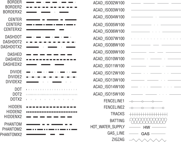
AutoCAD comes with several linetypes, as shown in Figure 5-14. ISO linetypes are designed to be used with specific plotted line widths and linetype scales. For example, if you’re using a pen width of 0.5 mm, set the linetype scale of the drawing to 0.5 as well. (See Chapter 16 for more information on plotting and linetype scale.) You can also create your own linetypes (see Chapter 27, “Managing and Sharing Your Drawings”).
Linetypes that contain text, such as the gas line sample at the bottom of Figure 5-14, use the current text height and font to determine the size and appearance of the text displayed in the line. A text height of 0 displays the text properly in most cases. See Chapter 10, “Adding Text to Drawings,” for more on text styles.
AutoCAD stores linetype descriptions in an external file named Acad.lin, or Acadiso.lin for metric users. You can edit this file in a text editor like Notepad to create new linetypes or to modify existing ones. You’ll see how this is done in Chapter 27.
Adding a Linetype to a Drawing
To see how linetypes work, you’ll add a DASHDOT line in the bathroom plan to indicate a shower curtain rod:
1. Open the Layers Properties Manager, and select All from the filter list.
2. Click New Layer, and then type Pole↵ to create a new layer called Pole.
If you’re in a hurry, you can simultaneously load a linetype and assign it to a layer by using the Layer command. In this exercise, you enter -Layer↵ at the Command prompt. Then enter L↵,DASHDOT↵, and Pole↵, and press ↵ to exit the Layer command.
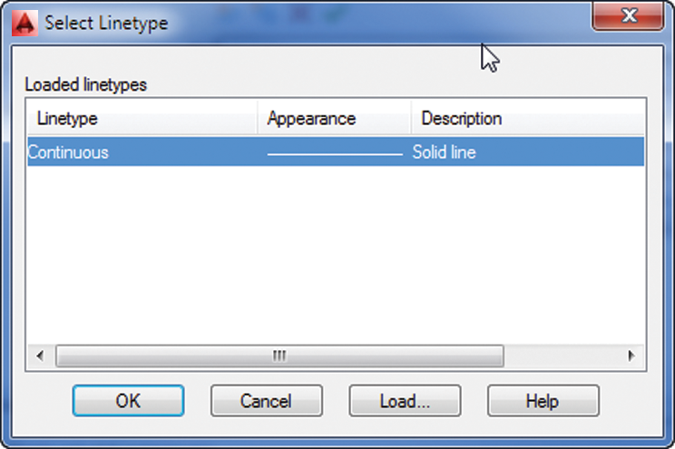
3. In the Pole layer listing, under the Linetype column, click the word
Continuous to open the Select Linetype dialog box. To find the Linetype column, you may need to scroll the list to the right by using the scroll bar at the bottom of the list (see
Figure 5-15).
The word Continuous truncates to Contin when the Linetype column is at its default width and the Continuous option is selected.
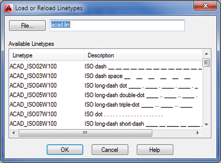
4. The Select Linetype dialog box offers a list of linetypes from which to choose. In a new file, such as the Bath file, only one linetype is available by default. You must load any additional linetypes you want to use. Click the Load button at the bottom of the dialog box to open the Load Or Reload Linetypes dialog box. Notice that the list of linetype names is similar to the layer drop-down list. You can sort the names alphabetically or by description by clicking the Linetype or Description heading at the top of the list (see
Figure 5-16).
5. In the Available Linetypes list, scroll down to locate the DASHDOT linetype, click it, and then click OK.
Notice that the DASHDOT linetype is added to the linetypes available in the Select Linetype dialog box.
6. Click DASHDOT to highlight it; then click OK. DASHDOT appears in the Pole layer listing under Linetype.
7. With the Pole layer still highlighted, click the Set Current button to make the Pole layer current.
8. Exit the Layer Properties Manager.
9. Turn off Object Snap mode; then draw a line across the opening of the tub area, from coordinate 4′-4″,1′-10″ to coordinate 4′-4″,6′-10″. Metric users should draw a line from coordinate 133,56 to 133,208.
10. Press ↵ to finish the line.
Controlling Linetype Scale
Although you’ve designated this as a DASHDOT line, it appears solid. Zoom in to a small part of the line and you’ll see that the line is indeed as you specified.
Because your current drawing is at a scale of 1″ = 1′, you must adjust the scale of your linetypes accordingly. This too is accomplished in the Linetype Manager dialog box. Here are the steps:
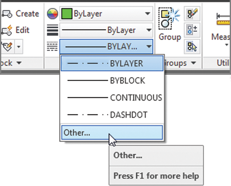
1. Click the Linetype drop-down list in the Home tab’s Properties panel and select Other.
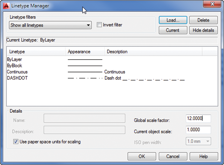
2. The Linetype Manager dialog box opens. Click the Show Details button in the upper-right corner of the dialog box. Some additional options appear at the bottom (see
Figure 5-17).
The Linetype Manager dialog box offers Load and Delete buttons that let you load or delete a linetype directly without having to go through a particular layer’s linetype setting.
3. Double-click the Global Scale Factor text box, and then type 12(metric users type 30). This is the scale conversion factor for a 1″ = 1′ scale (see the discussion of scale factors in Chapter 3, “Setting Up and Using the Drafting Tools”).
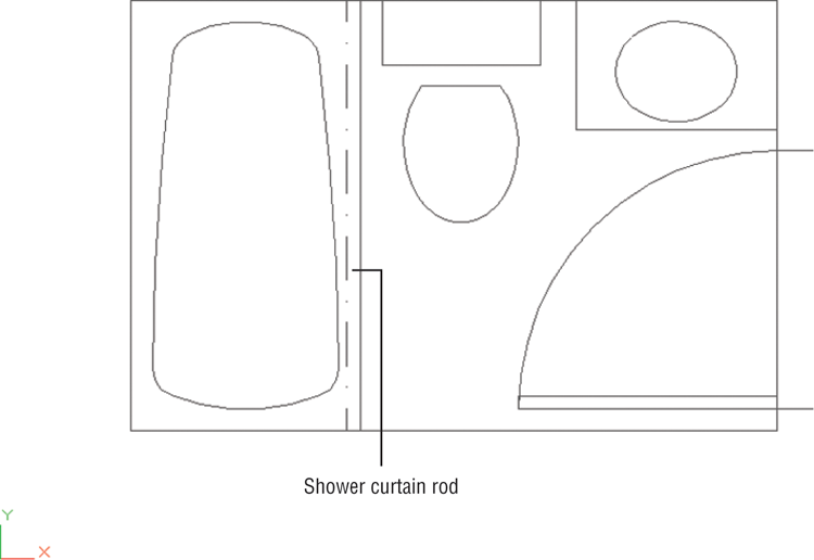
4. Click OK. The drawing regenerates and the shower curtain rod is displayed in the linetype and at the scale you designated.
5. Click the Zoom Previous tool from the Navigation bar or the Previous tool from the View tab’s Navigate 2D panel so your drawing looks like
Figure 5-18.
You can also use the Ltscale system variable to set the linetype scale. Type LTSCALE↵, and at the Enter new linetype scale factor <1.0000>: prompt, enter 12↵.
Linetypes Troubleshooting
If you change the linetype of a layer or an object but the object remains a continuous line, check the Ltscale system variable. It should be set to your drawing scale factor. If this doesn’t work, set the Viewres system variable to a higher value (see Appendix B, “Installing and Setting Up AutoCAD”). Viewres can also be set by the Arc And Circle Smoothness option in the Display tab of the Options dialog box. The behavior of linetype scales depends on whether you’re in Model Space or in a drawing layout. If your efforts to control linetype scale have no effect on your linetype’s visibility, you may be in a drawing layout. See Chapter 16 for more on Model Space and layouts.
Remember that if you assign a linetype to a layer, everything you draw on that layer will be of that linetype. This includes arcs, polylines, and circles. As explained in the sidebar “Assigning Colors, Linetypes, and Linetype Scales to Individual Objects” later in this chapter, you can also assign different colors and linetypes to individual objects rather than relying on their layer assignment to define color and linetype. However, you may want to avoid assigning colors and linetypes directly to objects until you have some experience with AutoCAD and a good grasp of your drawing’s organization.
In the previous exercise, you changed the global linetype scale setting. This affects all noncontinuous linetypes within the current drawing. You can also set the default linetype scale for all new objects with the Current Object Scale option in the Linetype Manager dialog box.
When individual objects are assigned a linetype scale, they’re still affected by the global linetype scale set by the Ltscale system variable. For example, say you assign a linetype scale of 2 to the curtain rod in the previous example. This scale is then multiplied by the global linetype scale of 12, for a final linetype scale of 24.
You can also set the default linetype scale for individual objects by using the Celtscale system variable. After it’s set, only newly created objects are affected. You must use the Properties palette to change the linetype scale of individual existing objects.
If the objects you draw appear in a different linetype from that of the layer on which they’re located, check the default linetype by selecting Other from the Linetype drop-down list on the Home tab’s Properties panel. Then, in the Linetype Manager dialog box, highlight ByLayer in the Linetype list and click the Current button. In addition, check the linetype scale of the object itself by using the Properties palette. A different linetype scale can make a line appear to have an assigned linetype that might not be what you expect. (See the sidebar “Assigning Colors, Linetypes, and Linetype Scales to Individual Objects.”)
Linetypes in Layouts
A system variable called Psltscale affects how layout viewports display linetypes. When the Psltscale system variable is set to 1, layout viewports display linetypes at the Ltscale setting, which is usually incorrect for the 1-to-1 scale of the layout. When Psltscale is set to 0, linetypes appear in layout viewports in the same way they appear in the Model tab.
Adding the Final Detail
If you’re working through the tutorial, your final task is to set up an insertion point for the current drawing to facilitate its insertion into other drawings in the future. Follow these steps:
1. Type BASE↵.
2. At the Enter base point <0′-0″,0′-0″,0′-0″>: prompt, use the Endpoint object snap to pick the upper-left corner of the bathroom. The bathroom drawing is complete.
3. Click the Save tool in the Quick Access toolbar to record your work up to now.
Controlling Lineweights
You may have noticed a Lineweight column in the Layer Properties Manager. If you click this option for a given layer, the Lineweight dialog box opens, which enables you to control the plotted thickness of your lines. Plotted lineweights can also be set through direct object property assignment. You can view lineweights as they will appear in your final plot by making setting changes in the Lineweight Settings dialog box, which you’ll learn about in Chapter 16.
With the Lineweight option and Lineweight Settings dialog box, you have greater control over the look of your drawings. This can save time because you don’t have to print your drawing just to check for lineweights. You’ll be able to see how thick or thin your lines are as you edit your drawing. You’ll get a chance to delve into lineweights in Chapter 16.
Keeping Track of Blocks and Layers
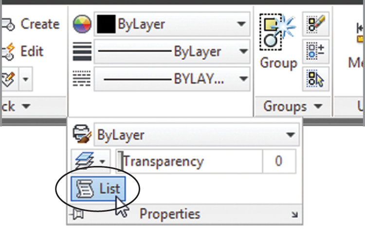
The Insert dialog box and the Layer Properties Manager let you view the blocks and layers available in your drawing by listing them in a window. The Layer Properties Manager also includes information about the status of layers. However, you may forget the layer on which an object resides. You’ve seen how the Properties option on the context menu shows you the properties of an object. The List tool in the Properties panel also enables you to get information about individual objects.
Use these steps to see an alternate way to view the properties of a block:
1. Click the List tool from the Home tab’s expanded Properties panel.
If you just want to check quickly to see where an object is located, click it. Its layer will appear in the layer drop-down list of the Layers panel.
2. At the Select objects: prompt, click the Tub block and then press ↵ to open the AutoCAD Text Window.
3. The Command window expands to display a list that shows not only the layer on which the tub is located, but also its space, insertion point, name, rotation angle, and scale. If the Command window is in its docked position, the AutoCAD Text Window appears with the list.
The information in the expanded Command window or the AutoCAD Text Window, except the handle listing, is duplicated in the Properties palette. However, having the data in the Command window or Text Window gives you the flexibility to record it in a text file in case you need to store data about parts of your drawing. You can also use the AutoCAD Text Window to access and store other types of data regarding your drawings.
The Space property listed for the Tub block designates whether the object resides in Model Space or Paper Space. You’ll learn more about these spaces in Chapter 8 and Chapter 16.
Getting a Text File List of Layers or Blocks
With complex drawings, it can be helpful to get a text file that lists the layers or blocks in your drawing. You can do this by using the log-file feature in AutoCAD. At the Command prompt, enter Logfilemode↵ and then enter 1↵. Type-La↵ ?↵↵ (don’t forget the hyphen at the beginning of the La command). If your list of layers is extensive, you may be asked to press ↵ to continue. Do so. Your list of layers appears in the AutoCAD Text Window. For a list of blocks, enter -Insert↵?↵↵. When you’ve obtained your list, close thelog-file feature by typing Logfilemode↵0↵.
Assigning Colors, Linetypes, and Linetype Scales to Individual Objects
If you prefer, you can set up AutoCAD to assign specific colors and linetypes to objects instead of having objects take on the color and linetype settings of the layer on which they reside. Normally, objects are given a default color and linetype called ByLayer, which means each object takes on the color or linetype of its assigned layer. (You’ve probably noticed the word ByLayer in the Properties panel and in various dialog boxes and tool palettes.)
Use the Properties panel to change the color or linetype of existing objects. This panel lets you set the properties of individual objects. For new objects, use the Object Color drop-down list on the Properties panel to set the current default color to red (for example) instead of ByLayer. Then everything you draw will be red, regardless of the current layer color. The Object Color drop-down list also offers a Select Colors option that opens the Select Color dialog box you saw earlier in this chapter.
For linetypes, you can use the Linetype drop-down list in the Properties panel to select a default linetype for all new objects. The list shows only linetypes that have already been loaded into the drawing, so you must first load a linetype before you can select it.
Another possible color and linetype assignment is ByBlock, which you also set with the Properties panel. ByBlock makes everything you draw white until you turn your drawing into a block and then insert the block on a layer with an assigned color. The objects then take on the color of that layer. This behavior is similar to that of objects drawn on layer 0. The ByBlock linetype works similarly to the ByBlock color.
You can set an object or set of objects to ByLayer or ByBlock using the SETBYLAYER command. Click the Set To ByLayer tool in the Home tab’s expanded Modify panel or type SETBYLAYER↵, select the objects you want to modify, and follow the prompt.
Finally, if you want to set the linetype scale for each individual object instead of relying on the global linetype scale (the Ltscale system variable), you can use the Properties palette to modify the linetype scale of individual objects. In place of using the Properties palette, you can set the Celtscale system variable to the linetype scale you want for new objects.
As mentioned earlier, stay away from assigning colors and linetypes to individual objects until you’re comfortable with AutoCAD; even then, use color and linetype assignments carefully. Other users who work on your drawing may have difficulty understanding your drawing’s organization if you assign color and linetype properties indiscriminately.
Once the log-file feature is closed, you can use Windows Notepad to open the AutoCAD log file located in the C:UsersUser NameAppDataLocalAutodeskAutoCAD 2014R19.1enu folder. You’ll need to change the File Of Type option to All Files. The name of the log file will start with the name of the current drawing, followed by a series of numbers and the .log filename extension, as in 04c-bath-metric_1_1_6500.log.
If you have difficulty finding the log file, enter (getvar "logfilepath") at the AutoCAD Command prompt to get a listing of the log-file location. The log file may also be in a hidden folder, so you may have to turn off the hidden folder setting in Windows Explorer. See Appendix B for instructions on how to do this.
With the log-file feature, you can record virtually anything that appears at the Command prompt. You can even record an entire AutoCAD session. The log file can also be helpful in constructing script files to automate tasks. (See Chapter 26, “Customizing Toolbars, Menus, Linetypes, and Hatch Patterns,” for more information on scripts.) If you want a hard copy of the log file, print it from an application such as Windows Notepad or your favorite word processor.
Using Excel to Analyze Large Layer Lists
You may encounter a drawing that has a very long list of layers. To help you analyze the layers in a drawing, you can copy the layer list into Microsoft Excel by doing the following: Open the Layer Properties Manager and press Ctrl+A to select the entire layer list. Press Ctrl+C to copy the list to the Clipboard, and then open Excel. Press Ctrl+V to paste the list into Excel.
The Bottom Line
Organize information with layers. Layers are perhaps the most powerful feature in AutoCAD. They help to keep drawings well organized, and they give you control over the visibility of objects. They also let you control the appearance of your drawing by setting colors, lineweights, and linetypes.
Master It Describe the process of creating a layer.
Control layer visibility. When a drawing becomes dense with information, it can be difficult to edit. If you’ve organized your drawing using layers, you can reduce its complexity by turning off layers that aren’t important to your current session.
Master It Describe two methods for hiding a layer.
Keep track of blocks and layers. At times, you may want a record of the layers or blocks in your drawing. You can create a list of layers using the log-file feature in AutoCAD.
Master It Where do you go to turn on the log-file feature?