Chapter 27
Managing and Sharing Your Drawings
Whether you’re a one-person operation working out of your home or one of several hundred Autodesk® AutoCAD® software users in a large company, file sharing and file maintenance can become the focus of much of your time. In our interconnected world, the volume of messages and files crossing our paths seems to be increasing exponentially. In addition, the Internet has enabled us to be more mobile, adding yet more complexity to file management and data sharing tasks.
In this chapter, you’ll learn about some of the tools AutoCAD offers to help you manage your files and the files you share with others. You’ll also examine some general issues that arise while using AutoCAD in a workgroup environment. You may find help with problems you’ve encountered when using AutoCAD.
In this chapter, you will learn to:
- Share drawings online
- ePublish your drawings
- Get started with Autodesk 360
- Manage your drawings with DesignCenter and the tool palettes
- Search your drawing library with Content Explorer
- Establish office standards
- Convert multiple layer settings
Sharing Drawings Online
AutoCAD gives you tools that enable you to post drawings on the Internet that others can view and download. In the architecture, engineering, and construction (AEC) industry in particular, this can mean easier access to documents needed by contractors, engineers, cost estimators, and others involved in the design, bidding, and construction of building projects. Suppliers of products can post symbol libraries of their products or even 3D solid models.
In the following sections, you’ll learn about the tools AutoCAD provides for publishing and accessing drawings over the Internet (and on any local or wide area network). You’ll start by looking at one of the most common uses of the Internet: file transmission.
Sharing Project Files with eTransmit
Whether you’re a one-person office or a member of a 50-person firm, you’ll eventually have to share your work with others outside your building. Before eTransmit existed as a feature in AutoCAD, you had to examine what you were sending carefully to make sure you included all the ancillary files needed to view or work on your drawings. Xref, font, and custom linetype files all had to be included with the drawings that you sent to consultants or partners in a project, and often one of these items was omitted from the transmission.
By using eTransmit, you can quickly collect all your project drawings into a single archive file, or you can store the files in a separate folder for later processing. This collection of files is included with a report file as a transmittal. Try the following to see how eTransmit works:
Figure 27-1 Creating a transmittal
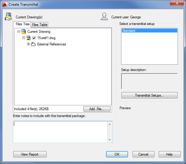
Figure 27-2 Choose whether to create from scratch or edit an existing transmittal.
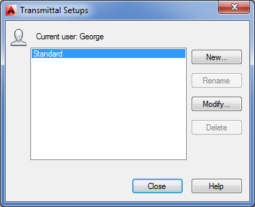
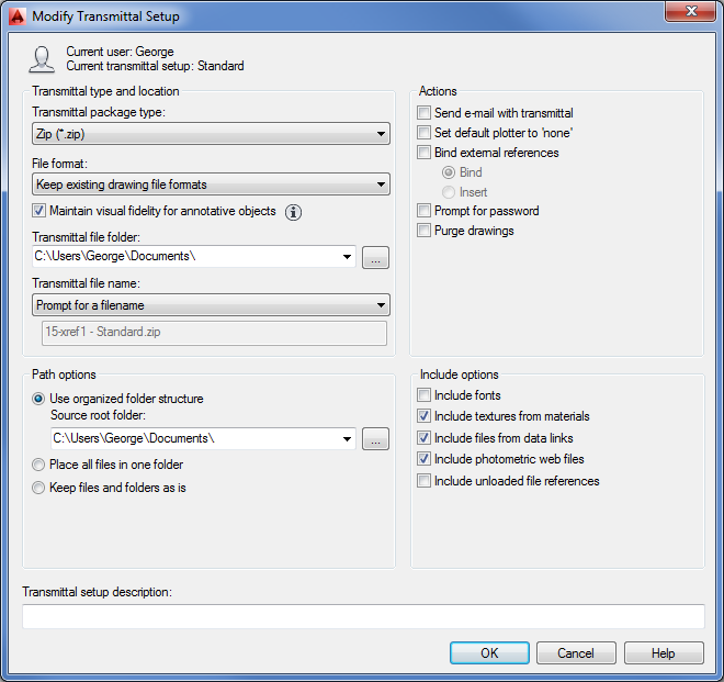
Figure 27-3 Set your transmittal options.
You probably noticed that you can create additional transmittal setup options in the Transmittal Setups dialog box. That way, you can have multiple transmittal options on hand that you don’t have to set up each time a different situation arises. For example, you might have the Standard setup configured to create a Zip file and another setup configured to copy the files into a folder. A third setup might be created with a password.
Several options are available for configuring the transmittal setup. Table 27-1 gives a rundown of those options.
Table 27-1: Modify Transmittal Setup dialog box options
| Option | Purpose |
| Transmittal Package Type | Lets you select Folder, Zip, or Self-Extracting Executable. |
| File Format | Lets you select 2013, 2010, 2007, 2004, or 2000 file formats in case your recipient requires an earlier version. |
| Maintain Visual Fidelity For Annotative Objects | Maintains visual fidelity for annotative objects when drawings are viewed in AutoCAD 2007 and earlier. |
| Transmittal File Folder | Lets you determine the location for your transmittal package. |
| Transmittal File Name | Not available if you select Folder as the transmittal package type. Options are Prompt For A Filename, Overwrite If Necessary, and Increment File Name If Necessary. |
| Use Organized Folder Structure | Preserves the folder structure for the files in the transmittal. This can be important when Xref and other files are located across several folder locations. |
| Place All Files In One Folder | Self-explanatory. |
| Keep Files And Folders As Is | Preserves the entire folder structure for the files in the transmittal. |
| Include Fonts | Tells AutoCAD to include the font files in the transmittal. |
| Include Textures From Materials | Lets you include bitmap files that are part of a file’s material settings. |
| Include Files From Data Links | Lets you include external data-link files for tables. |
| Include Photometric Web Files | Lets you include photometric web files for 3D lighting models. |
| Include Unloaded File References | Lets you include references for unloaded Xref files. |
| Send E-Mail With Transmittal | Lets you send an email with the files included as an attachment. |
| Set Default Plotter To ‘None’ | Removes any reference to printers or plotters that you’ve set up for the drawing. (The type of printer you’ve set up for your files is stored with the drawing file.) |
| Bind External References | Lets you bind external references to the drawings that contain them if it isn’t important for the recipient to maintain the external references as separate drawings. |
| Prompt For Password | Gives you the option to password-protect the transmittal file. |
| Purge Drawings | Purges drawings of unused elements. |
| Transmittal Setup Description | Lets you add a description to the transmittal file. |
eTransmit gives you a quick way to package a set of files to be sent to others working on the same project. But you may need to offer a wider distribution of your files. You might want to let others view and plot your drawings from a website without exposing your drawing database to anyone who might visit your site. If this sounds like something you would be interested in, you’ll want to know about the AutoCAD DWF file format, which lets anyone view AutoCAD files whether or not they own the program. You’ll learn more about the DWF file format in the section “ePublishing Your Drawings” later in this chapter.
Protecting AutoCAD Drawing Files
Because AutoCAD drawings specify the methods and materials used to produce an object or a building, they are frequently treated like legal documents. After an AutoCAD drawing is issued, it’s often archived and guarded as a legal record of a design. For this reason, many AutoCAD users are concerned about possible tampering with drawings that are sent to third parties. Even minor unauthorized changes to a drawing can have major repercussions on the integrity of a design.
AutoCAD 2014 offers tools that can help minimize file tampering. The eTransmit feature offers a password-protection option to reduce the possibility of unauthorized tampering with transmittal files. AutoCAD also offers password protection for individual files as well as a digital signature feature that helps protect both the author of a drawing and the recipient in the event of file tampering.
Adding Password Protection to Files
The basic type of file protection is password protection of individual files. AutoCAD offers password protection through the Save Drawing As dialog box and the Options dialog box.
To add a password to a drawing when you save it, do the following:
In addition to adding password protection through the Save Drawing As dialog box, you can use the Options dialog box:
As a third option, you can enter Securityoptions↵ at the Command prompt to go directly to the Security Options dialog box.
After you’ve added a password, anyone attempting to open the file will be asked to provide the password. This includes any attempt to use the file as an Xref or a file insertion.
Using a Digital Signature
In addition to password protection, you can use a digital signature to authenticate files. A digital signature can’t prevent someone from tampering with a file, but it offers a way to validate whether a file has been modified after it has been saved. This protects you in the event that your file is unofficially altered. It also protects the recipient of your file by verifying the file’s authenticity and by verifying that it was not altered from the time it left your computer.
The first time you attempt to use the digital signature feature, you see a message telling you that you need a digital ID. AutoCAD uses a digital ID issued by any certificate authority, such as VeriSign, a company that specializes in Internet security. The VeriSign digital ID service is fee based, with prices ranging from about $15 for a basic one-year enrollment to nearly $700 for a professional-level ID. A free 60-day trial is also offered. The following steps show how to acquire a digital ID:
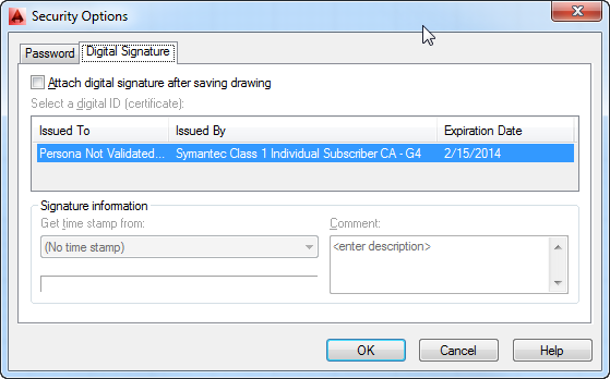
After you’ve obtained a digital ID, the signature resides in the Registry on your computer. You can then access the digital ID from AutoCAD by using the Digital Signature tab of the Security Options dialog box. Here are the steps:
Figure 27-4 Attach a signature.
The next time you save the file, depending on the level of security you chose during the digital ID setup, you may be prompted for a password. After you enter the password, the file is saved.
The next time the file is opened, you’ll see the Digital Signature Contents dialog box (see Figure 27-5), which verifies that no one has tampered with the drawing.
You’ll also see a stamp icon in the lower-right corner of the AutoCAD window. You can click this icon at any time to view the file’s digital signature status. You can also issue the SigValidate command to view the status.
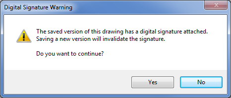
A file containing a digital signature displays a warning when the user attempts to save the file after making modifications (see Figure 27-6). If the user continues to save the file, the signature is detached and no longer displays the Digital Signature Contents dialog box when opened.
Figure 27-5 The signature is verified when the file opens.
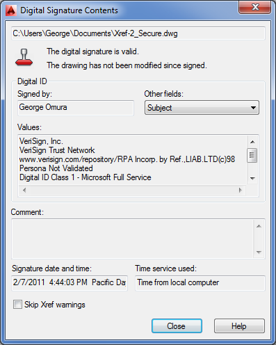
Figure 27-6 Checking signature status
If you need to update a drawing that contains your digital signature, you can do so and then use the Security Options dialog box to reissue the digital signature.
Adding Your Digital Signature to Multiple Files
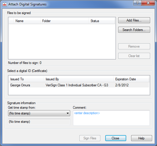
If you have multiple files to which you’d like to attach your digital signature, you should use the Attach Digital Signatures utility. This program runs outside AutoCAD, and it provides a convenient way to attach your digital signature to a set of drawings. Here’s how it works:
Figure 27-7 Signing multiple files
If you exchange AutoCAD drawings regularly with clients and consultants, you’ll want to obtain a digital ID and use the digital signature feature. Be aware, however, that because this feature was new in AutoCAD 2004, it works only if you exchange files with others using AutoCAD 2004 or later. In fact, a quick way to remove a digital signature from a file is to save the file in the AutoCAD 2000 or Release 14 file format.
If you intend to use the password feature in conjunction with your digital signature, you must add the signature first before adding the password.
ePublishing Your Drawings
The features discussed so far are intended mostly for exchanging files with others who need to work directly with your AutoCAD files. However, there are always associates and clients who need to see only your final drawings and don’t care whether they get AutoCAD files. Alternatively, you might be working with people who don’t have AutoCAD but still need to view and print your drawings. For those non-AutoCAD end users, AutoCAD offers the DWF file format.
You can think of the DWF file format as a kind of Adobe Acrobat file for AutoCAD drawings. DWF offers a way to get your plans and design ideas in the hands of more people more easily. With the help of the free Autodesk® DWF™ Viewer—equivalent to the Adobe Reader for Acrobat PDF documents—DWF files can be viewed using the same types of pan and zoom tools available in AutoCAD, which allows greater detail to be presented in your drawings. In addition, you can embed URL links that can open other documents with a single mouse click. These links can be attached to objects or areas in the drawing.
You can also print DWF files using your Windows system printer or plotter, all without having AutoCAD installed. A single DWF file can contain multiple drawing sheets, so you can combine a complete set of drawings into one DWF file. By default, AutoCAD saves DWF files in the DWFx format that is compatible with the Windows 8, Windows 7 and Vista XPS formats.
Exchanging Drawing Sets
Imagine that you’re working on a skylight addition to a house and you need to send your drawings to your client for review. In addition to the skylight plans, you want to include some alternate floor plans that your client has asked you to generate. In this exercise, you’ll put together a set of drawings that will become a single DWF file that you’ll send as an email attachment to your client:
Figure 27-8 Choosing the layouts to publish
At this point, you could go ahead and create a DWF file. However, suppose you want to include layouts from a file that isn’t currently open? The following steps show you how to accomplish this:
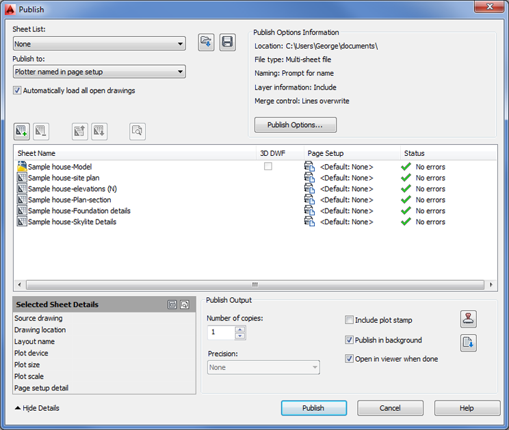
All the sheets your client needs appear in the list box. You’re ready to create the DWF file:
You may notice that when you click the Publish button in the previous exercise, AutoCAD behaves as if it’s printing the layouts in your list—and that is exactly what it’s doing. AutoCAD uses its own DWF printer driver to “print” your drawings to a DWF file. AutoCAD uses the layout settings from the Plot dialog box for each layout to produce the DWF pages.
Exploring Other Publish Options
A few more options are available when you use the Publish feature. Let’s take a moment to review some of the options in the Publish dialog box toolbar:
- The Preview tool lets you preview a sheet based on the current settings.
- The Add Sheets tool lets you add sheets to the list. The Remove Sheets tool removes a selected item from the list.
- The Move Sheet Up and Move Sheet Down tools let you move an item in the list up and down. These are important options because the order of drawings in the list determines the order that the drawings will appear in the Autodesk DWF Viewer. The item at the top of the list appears first, the next one on the list is second, and so on.
- The Load Sheet List and Save Sheet List tools let you load and save the list you’ve compiled, respectively. It’s a good idea to save your list in case you need to reproduce the DWF file at some future date.
- You can use the Plot Stamp Settings tool to specify the data you want to include in the plot stamp. This tool opens the Plot Stamp dialog box. (See Bonus Chapter 3, “Hardware and Software Tips,” for more on the Plot Stamp dialog box.)
Context Menu Options
If you right-click an item or a set of items in the Publish dialog box list box, you see a menu with the standard options mentioned earlier plus some additional options. You’ll want to know about a few of these options.
By default, AutoCAD applies the existing layout settings for each layout when it produces the DWF file. These are the settings found in the Plot Or Page Setup dialog box and include the sheet size, scale, and page orientation. The Change Page Setup option lets you use a different set of layout settings for a selected layout in the list. To use this option, you must have saved a page setup in the file’s Page Setup or Plot dialog box. (See Chapter 8 for more on the Page Setup dialog box and its options.) You can import a page setup from a different AutoCAD file, or you can assign a page setup to a sheet. Do this by clicking the sheet name and selecting a page setup from the list box that appears in the Page Setup column.
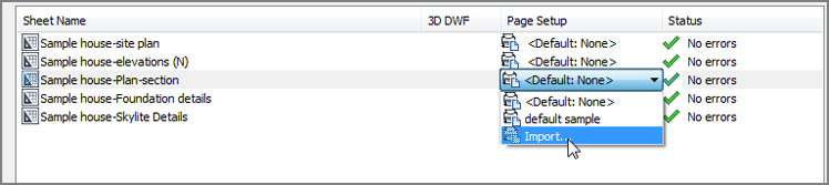
To change the page setup for multiple sheets, select the sheets from the list first and then select the setup from the list box.
If you happen to have two layouts with the same name, right-click a layout name, and then select the Rename Sheet option on the context menu to rename a layout. The Copy Selected Sheets option adds copies of selected layouts to the list. The copies have the word copy appended to their names. The last two items in the context menu let you control what is displayed in the list box. Include Layouts When Adding Sheets controls whether layouts are automatically imported from a drawing into the list box. Include Model When Adding Sheets controls whether Model Space views are automatically imported from a drawing into the list box.
The Publish Options Dialog Box
You can set up additional options by clicking the Publish Options button in the Publish dialog box. You’ll then see the Publish Options dialog box (see Figure 27-9).
Figure 27-9 Publish Options dialog box
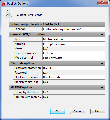
This dialog box offers options for the location and type of output. The Default Output Location group lets you select the location for DWF files. The General DWF/PDF Options group lets you choose between a multisheet DWF file, which combines multiple sheets into one file, and single-sheet DWF files, which create a file for each sheet. If you choose the multisheet file option, you have the added option to specify a default name for your DWF files or to have AutoCAD prompt you for a name each time you create a DWF file. The DWF Data Options group lets you add password protection to the DWF file by using the Password option. If your drawing contains 3D information, you can use the options in the 3D DWF Options group, which control Xref hierarchy and materials.
Creating a DWF File by Using the Plot Dialog Box
Another way to create DWF files is through the Plot dialog box. If you need to create a DWF file of only a single sheet, you may want to use the Plot dialog box because it’s a simple and familiar procedure.
Open the file that you want to convert to DWF, and then proceed as if you’re going to plot the drawing. In the Plot dialog box, select DWFx ePlot (XPS Compatible).pc3 or DWF6 ePlot.PC3 from the Name drop-down list in the Printer/Plotter area. The DWFx ePlot (XPS Compatible).pc3 option creates a file that is readable in Windows 8, Windows 7 or Windows Vista without the need for any special viewing program.
Proceed with the plot the normal way. When AutoCAD would normally send the drawing to the printer, you’ll see a dialog box asking you to enter a name for your plot file and finish with the rest of the plot. You can control the DWF plot as you would any plot.
In addition to using the settings available in the Plot dialog box, you can make some special configuration adjustments to the DWF plotter configuration file. Here is where to find those configuration settings:
Figure 27-10 Controlling the plotter configuration file
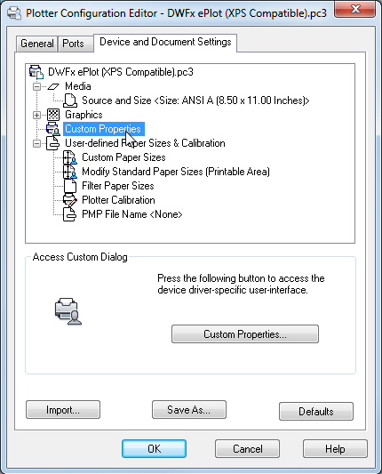
After you select your custom configuration settings in step 5, you needn’t open the Plotter Configuration Editor dialog box again the next time you plot a DWF file. If you save your new settings as a new PC3 file, you can select it from the File drop-down list in the Plotter Configuration group. You don’t have to reenter the custom settings.
You can either use the Publish feature described in the previous section to create single or multiple DWF files or create DWF files directly through the Plot dialog box. You can post the output from either method to a website to offer a wide distribution of your drawings. Just create a link to the DWF file from your web page. Be aware that persons attempting to view your DWF file from a web browser will need a copy of the free Autodesk DWF Viewer program that lets them view AutoCAD DWF files. The Autodesk DWF Viewer is automatically installed with AutoCAD 2014.
Sharing Files with Autodesk 360
Whether you share native AutoCAD DWG files or share files using the DWF format, you have a number of ways to convey the files to those who need them. Downloading from websites, transferring via FTP, and exchanging through email are all common methods for sharing files, but they are limited and can leave a user wanting more flexibility.
Autodesk offers the free Autodesk 360 service, which enables you to share files in a much more open and organized fashion. With Autodesk 360, you can make files available to others in a way that is similar to how you would make files available on an FTP site or a website, with the addition of more easily controlled access. You can track the shared history of a document or set of documents and organize files to suit nearly any project requirement.
Getting Started with Autodesk 360
To appreciate what Autodesk 360 can do for you, you’ll want to try out some of its features. The entry point to the cloud service is the Autodesk 360 Sign In option in the InfoCenter. Try the following to get started:
Figure 27-11 The Sign In To Autodesk 360 menu option and the Autodesk 360 welcome window
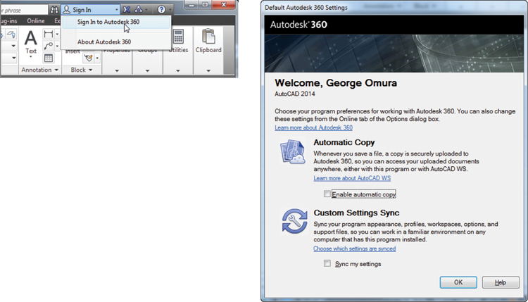
Figure 27-12 The InfoCenter Sign In drop-down list with new options
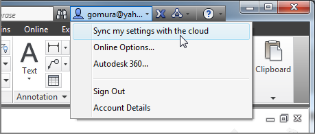
Figure 27-13 The Autodesk Cloud Documents page showing several documents
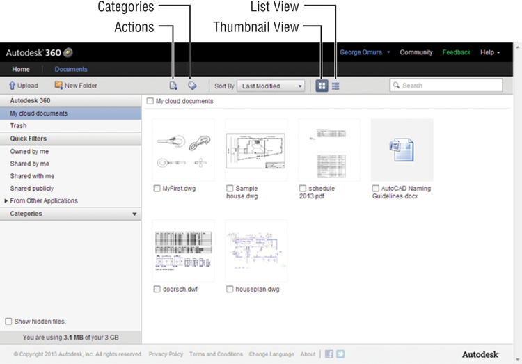
The Autodesk Cloud Documents page has three main parts. The largest area is a file view panel, where your files appear. Across the top is the menu bar that offers a set of actions you can apply to your files. To the left is a column of display filters that help you keep your drawings organized.
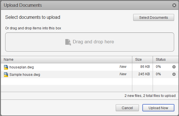
Let’s take a look at the menu bar. You can click the Upload option to upload files. This option opens the Upload Documents dialog box. You can then click and drag files into the Drag And Drop Here panel. The filename appears in the list box below (Figure 27-14). You can also just click and drag files into the blank file area to open the Upload Documents dialog box.
Figure 27-14 The Upload Documents dialog box
The New Folder option creates new folders in the current file view panel. To the right of the New Folder option are two icons: Actions and Categories. To use these icons, you first need to select a file or set of files from the file view panel. Files can be selected by clicking the check box next to the filename. The Actions icon displays a menu that offers options to download, share, move, rename, or delete your files.
The Categories icon displays a menu that enables you to assign your files to a category that you create. You can create categories in the panel to the left by clicking the arrowhead to the right of the Categories title. A file can be assigned to multiple categories.
The Actions and Categories icons appear in several places in the Autodesk Cloud site so that no matter where you are, you always have the Actions or Categories icons available. For example, if you hover over a file in the file view panel, you will see the icons along with a magnifying glass icon you can click to display an enlarged view of the thumbnail and a comments icon that enables you to add a text comment to the file.
Sharing Files
When you select a file and click the Actions icon, you’ll see two Sharing options: Private Sharing and Public Sharing. If you want to share a drawing with another Autodesk 360 user, you can select the Private Sharing option. You are then asked to supply the email address of the person with whom you want to share your drawing. After you complete this step, the file will appear in the file panel of the person you are sharing with.
The Public Sharing option enables you to share drawings with people who do not have an Autodesk ID account. Before you can share publicly, you will first have to turn on Public Sharing for the file. To do this, double-click the file to go to the Document Details view (Figure 27-15).
Figure 27-15 The Document Details view
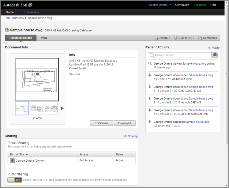
Scroll down to the bottom of the view to the Sharing panel. At the bottom of the Sharing panel, click the Off button to change the Public Sharing status to On (Figure 27-16).
Figure 27-16 The Public Sharing option
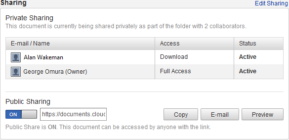
Finally, click the E-Mail button. If you are logged into your email client, an email window appears with the subject filled in and a link to your shared drawing already included in the body of the email text. You only need to fill in the recipient information and send the email off. When the recipient receives the email, they can go to the link in the email to view or download the drawing.
If you want to see what your recipient sees in the link, you can click the Preview button in the Sharing panel of the Document Details view. Their view is similar to your Document Details view without the Sharing and Recent Activity information.
Editing Drawings Online
Autodesk Cloud is intended as a tool for collaboration, so it includes some basic editing features. The specific features depend on the type of file you have available in your file panel.
If you look back at Figure 27-15, you will notice the Edit Online button. Click this button and AutoCAD WS, a web-based AutoCAD drawing editor, opens the file (Figure 27-17.)
Figure 27-17 AutoCAD WS
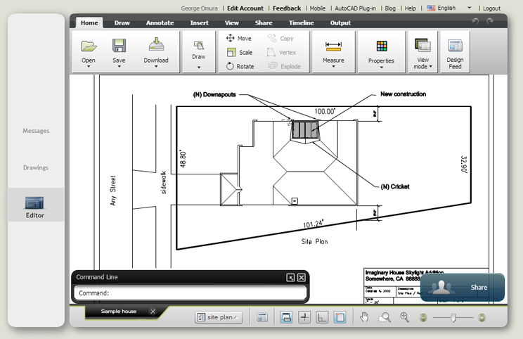
Notice that AutoCAD WS uses a Ribbon similar to the AutoCAD Ribbon you’ve been working with. It also has a command line for typing your commands. AutoCAD WS offers many of the most common editing tools so that users can make minor changes to a drawing. To exit AutoCAD WS, click the Logout option at the far right of the menu bar.
You can store other types of files in Autodesk 360, such as PDF and DWF files. When you view a PDF or DWF file using the View option, you are offered tools that enable you to add comments or zoom and pan your view (Figure 27-18).
Figure 27-18 Editing a DWF file
Controlling File Access
When you privately share a drawing, you can also control the level of access you give to the person you are sharing with. For example, you may want to allow only one person to view a file, whereas another person may require enough access to edit the file online.
Once you’ve shared a file, you can control the access level through the Share Document dialog box (Figure 27-19). To open this dialog box, click the Edit Sharing link to the right of the Sharing panel on the Document Details view (shown in Figure 27-15 earlier).
Figure 27-19 The Share Document dialog box
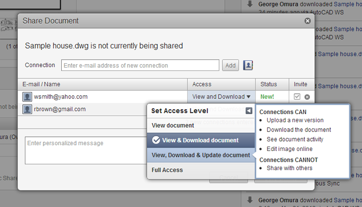
You can change the access level by clicking in the Access column of the dialog box. A list opens offering three levels of access: View DWG, View & Download DWG, and View, Download & Update DWG. When you hover over one of these options, a description of what the collaborator can and cannot do is listed to the right.
Tracking File Versions
A unique feature of Autodesk Cloud is its ability to track different versions of the same file. For example, you can upload a file, and then have a collaborator make changes to it online using AutoCAD WS. You can then click the Actions icon to check the version dates of the file (Figure 27-20).
Figure 27-20 The Document Versions dialog box
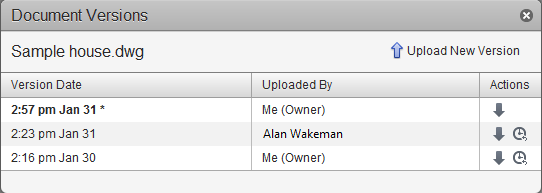
In addition, you can download any version using the down-pointing arrow in the Actions column or, as the owner of the file, revert to a prior version by clicking the clock icon. Even if you revert the file, the Document Versions dialog box will still display all of the versions of the file that have been uploaded or edited online.
As you can see from this brief tour of Autodesk 360, sharing files and collaborating with others is becoming much easier. You may want to spend some time on your own experimenting with the settings and features of Autodesk Cloud now that you’ve gotten your feet wet.
Collaborating with Others Using Design Feed
Besides sharing and editing files, you can also add comments and images to files shared on Autodesk 360 through the Design Feed feature. Design Feed gives you a way to communicate ideas through your drawings by enabling you to post messages and images directly onto your AutoCAD files. You can find Design Feed on the Autodesk 360 tab in the Share & Collaborate panel (see Figure 27-21).
Figure 27-21 Clicking the Design Feed tool

Click the Design Feed tool and the Design Feed palette opens (see Figure 27-22). If the drawing has not been saved to the Autodesk 360 site, you will see a message at the top of the Design Feed panel asking you to save to Autodesk 360. Once this is done, you can start to add comments to the drawing that others can view and respond to. The comments will appear in the middle portion of the panel.
Figure 27-22 Design Feed panel
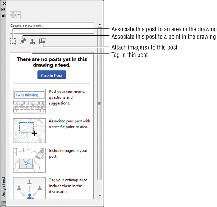
There are four tools just below the Create A New Post box:
- Associate this post to an area in the drawing
- Associate this post to a point in the drawing
- Tag in this post
- Attach image(s) to this post
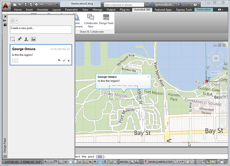
To use the area or point tool, click the tool icon and then click in the drawing to indicate the post’s location. Next, enter a message in the Create A New Post box. Click the Create Post button when you’re done. The Tag tool enables you to alert the recipient to your post via an email. The Attach Image tool will open a file dialog box enabling you to locate an image file to include with your post. Figure 27-23 shows a drawing with a post attached to an area.
When a recipient to your post views the drawing in Autodesk 360, they will see a post as a numbered icon. They can click the icon and the post associated with it will be highlighted in the Design Feed panel. They can then add their comments and replies to the post.
Figure 27-23 A drawing with a post attached to an area
Adding Hyperlinks to Drawings
AutoCAD offers the Hyperlink tool, which enables you to link any document to an AutoCAD object. Then, with a few clicks of your mouse, you can follow the links to view other drawings, text files, spreadsheets, or web pages. Hyperlinks persist even after exporting your drawing to a DWF file. You can then post that DWF file on a web page where others can gain access to those links.
Creating Hyperlinks
The following steps show you how to add links to a sample floor plan:
Figure 27-24 The door symbol in the houseplan.dwg file
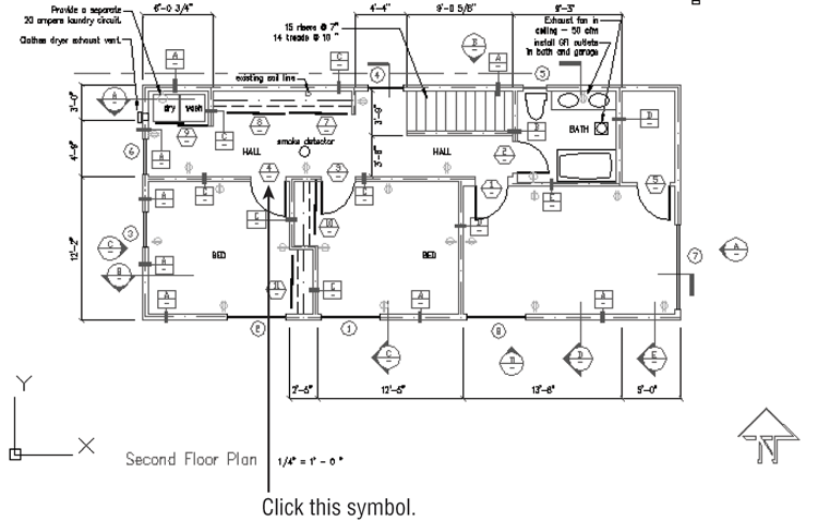
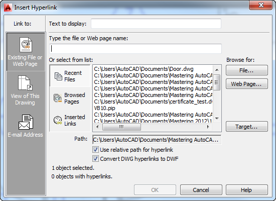
Figure 27-25 The Insert Hyperlink dialog box
The link you just created is stored with the drawing file. You can create a DWF file from this drawing, and the link will be preserved in the DWF file.
Now let’s see how you can use the link from within the AutoCAD file:
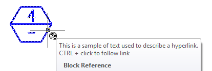
Figure 27-26 The hyperlink icon and tool tip
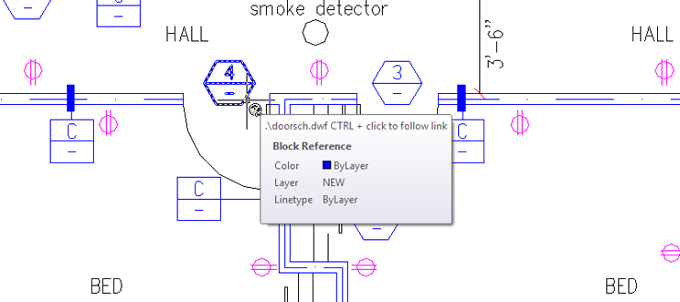
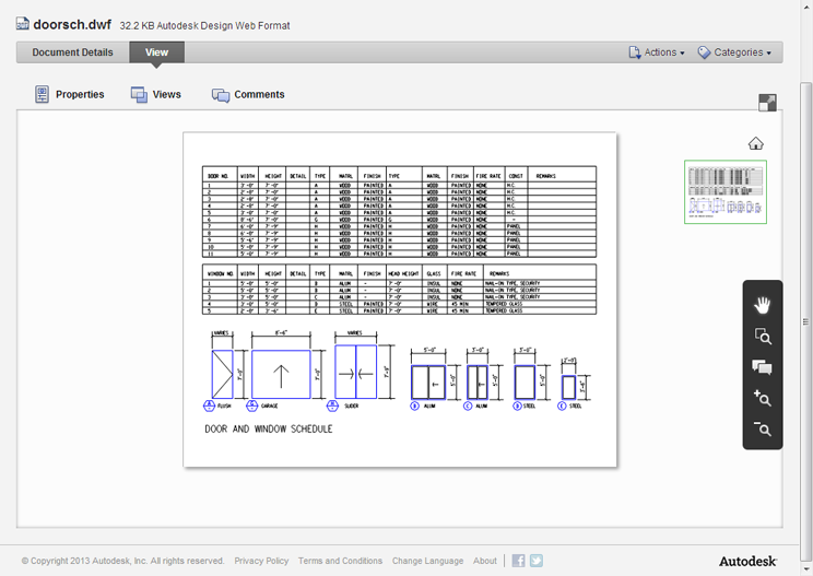
The Autodesk Design Review program opens and displays the file doorsch.dwf. If you installed the sample figures on another drive or folder location, the Hyperlink menu option will reflect that location.
You’ve used the doorsch.dwf file as an example in these exercises, but this could have been a text file, a spreadsheet, a database, or even another AutoCAD file. AutoCAD will start the application associated with the linked file and open the file.
Editing and Deleting Hyperlinks
You can edit or delete a hyperlink by doing the following:
Taking a Closer Look at the Hyperlink Options
You were introduced to the Insert Hyperlink dialog box, shown in Figure 27-25, in the previous exercises. Let’s take a moment to study this dialog box in a little more detail.
To specify a file or a website to link to, you can enter either a filename or a website URL in the Type The File Or Web Page Nameboxor use theOr Select From Listarea, which offers a list box and three button options. When you select one of the buttons, the list box changes to offer additional related options:
You can also use the three buttons to the right of the list box to locate specific files (the File button), websites (the Web Page button), or saved views (the Target button) in the current drawing.
As you saw in the exercise, the File button opens the Browse The Web – Select Hyperlink dialog box, which lets you locate and select a file from Autodesk 360, from your computer, from your local area network, or even from an FTP site. This is a typical AutoCAD open file dialog box with some additional features.
The Web Page button on the right opens a simplified web browser that lets you locate a web page for linking. In this dialog box, you can use the standard methods for accessing web pages, such as using the Look In drop-down list to select recently visited pages or entering a URL in the Name Or URL box. The page is then displayed in the main window of the dialog box.
If the selected hyperlink file is an AutoCAD DWG file, the Target button in the Insert Hyperlink dialog box opens the Select Place In Document dialog box, which lists the saved views in the drawing.
Views are subdivided by layout tabs. At the top is the Model Space tab listing, and below that are other layout tab listings. If the current drawing contains saved views, you see a plus sign next to the layout tab name. Click the plus sign to display a listing of the views in that layout.
At the top of the Insert Hyperlink and Edit Hyperlink dialog boxes is a box labeled Text To Display. When a hyperlink is added to an object in AutoCAD, AutoCAD will display a hyperlink icon whenever the cursor passes over the object. You can also include descriptive text that will display along with the icon by entering the description in the Text To Display box.
By default, the text is the name of the hyperlinked item that you select. You can change the text to provide a better description of the link.
There is a column of options at the far left in the Insert Hyperlink dialog box, labeled Link To. The top button, Existing File Or Web Page, displays the options discussed so far in this section. The other two buttons change the appearance of the Insert Hyperlink dialog box to offer different but familiar options:
Managing Your Drawings with DesignCenter and the Tool Palettes
As you start to build a library of drawings, you’ll find that you reuse many components of existing drawing files. Most of the time, you’ll probably be producing similar types of drawings with some variation, so you’ll reuse drawing components such as layer settings, dimension styles, and layouts. It can be a major task to keep track of all the projects on which you’ve worked. It’s especially frustrating when you remember setting up a past drawing in a way that you know would be useful in a current project but you can’t remember that file’s name or location.
AutoCAD offers DesignCenter™ to help you keep track of the documents you use in your projects. You can think of DesignCenter as a kind of super Windows Explorer that is focused on AutoCAD files. DesignCenter lets you keep track of your favorite files and helps you locate files, blocks, and other drawing components. In addition, you can import blocks and other drawing components from one drawing to another by using a simple click and drag. If you’ve been diligent about setting a unit format for each of your drawings, you can use DesignCenter to import symbols and drawings of different unit formats into a drawing and the symbols will maintain their proper size. For example, a 90 cm door symbol from a metric drawing can be imported into a drawing in Imperial units and DesignCenter will translate the 90 cm metric door size to a 35.43″ door.
Getting Familiar with DesignCenter
At first glance, DesignCenter looks a bit mysterious. But it takes only a few mouse clicks to reveal a tool that looks much like Windows Explorer. Try the following steps to get familiar with DesignCenter:
Figure 27-27 DesignCenter opens as a floating palette.
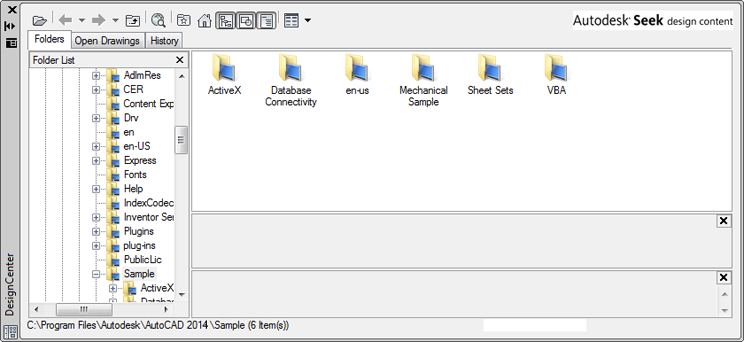
Figure 27-28 The components of the DesignCenter palette
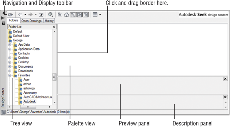
After you have it set up like this, you can see the similarities between DesignCenter and Windows Explorer. You can navigate your computer or network by using the Tree view, just as you would in Windows Explorer. There are a few differences, however, as you’ll see in the following exercise:
Figure 27-29 The DesignCenter display
You can also open and close the Preview panel by clicking the Preview tool in the DesignCenter toolbar. The preview can be helpful if you prefer viewing files and drawing components as a list in the main part of the Palette view.
Below the Preview panel is the Description panel. This panel displays any text information included with the drawing or drawing element selected in the Palette view. To add a description to a drawing that will be visible here, choose Drawing Utilities ⇒ Drawing Properties from the Application menu; to add a description to a block, use the Summary tab in the Block Definition dialog box.
You can open and close this panel by clicking the Description tool on the DesignCenter toolbar. Because the Basic Electronics.dwg file doesn’t have a description attached, the Description panel shows the message Last saved by: Autodesk.
Both the Preview and Description panels can offer help in identifying files for which you may be looking. After you find a file, you can click and drag it into a folder in the Tree view to organize your files into separate folders.
You can also add files to the Favorites folder by right-clicking and then choosing Add To Favorites. The file itself isn’t moved to the Favorites folder; instead, a shortcut to the file is created in the Favorites folder. If you want to work on organizing your Favorites folder, you can open a window to the Favorites folder by right-clicking a file in the Palette view and choosing Organize Favorites. A window to the Favorites folder appears.
Because you’ll be working with the sample drawings, go ahead and add the Projects folder to the Favorites folder:
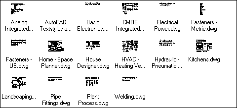
You can go beyond just looking at file listings. You can also look inside files to view their components:
Here, you can import any of the drawing components from the DesignCenter palette into an open drawing in AutoCAD. But before you try that, let’s look at a few other features of DesignCenter.
Opening and Inserting Files with DesignCenter
By using DesignCenter, you can more easily locate the files you’re seeking because you can view thumbnail preview icons. But often that isn’t enough. For example, you might want to locate all the files that contain the name of a particular manufacturer in an attribute of a drawing.
After you’ve found the file you’re seeking, you can load it into AutoCAD by right-clicking the filename in the Palette view and then choosing Open In Window. Try it with the following exercise:
If you want to insert a file into another drawing as a block, you can do so by clicking and dragging the file from the DesignCenter Palette view into an open drawing window. You can also right-click and select Insert As Block. You’re then prompted for the insertion point, scale, and rotation angle. If you prefer to use the Insert dialog box to insert a drawing from DesignCenter, right-click the filename in the Palette view and then choose Insert As Block. The Insert dialog box opens, offering you the full set of Insert options, as described in Chapter 4, “Organizing Objects with Blocks and Groups.”
Finally, you can attach a drawing as an Xref by right-clicking a file in the Palette view of DesignCenter and choosing Attach As Xref. The Attach External Reference dialog box opens, offering the insertion point, scale, and rotation options similar to the options in the Insert dialog box. This is the same dialog box described in Chapter 7, “Mastering Viewing Tools, Hatches, and External References.”
Finding and Extracting the Contents of a Drawing
Aside from the convenience of being able to see thumbnail views of your drawing, DesignCenter may not seem like much of an improvement over Windows Explorer. But DesignCenter goes beyond Windows Explorer in many ways. One of the main features of DesignCenter is that it enables you to locate and extract components of a drawing.
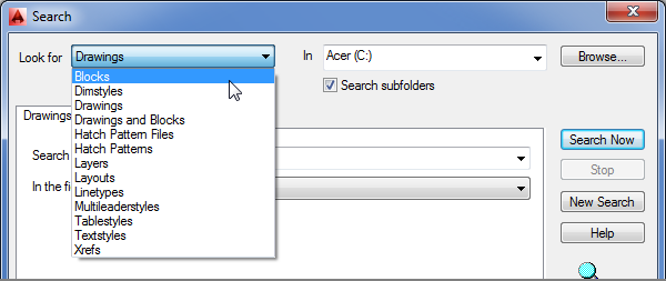
Imagine that you want to find a specific block in a drawing. You remember the name of the block, but you don’t remember the drawing into which you put it. You can search the contents of drawings by using DesignCenter’s Search dialog box. In the following exercise, you’ll search for a block named Kitchen2-metric among a set of files:
Figure 27-30 Select Blocks from the Look For drop-down list.
Exploring the Search Options
As you saw from the previous example, the Search dialog box can be helpful in finding items that are buried in a set of drawings. In the exercise, you searched for a block, but you can search for any named drawing component, including attribute data and text. For example, if you want to find all attributes that contain the name ABC Manufacturing Company in your drawings, you can do so with the DesignCenter Search dialog box. Table 27-2 shows a summary of its features. When you select Drawings from the Look For drop-down list, you see a set of additional tabs in the Search dialog box, as described in Table 27-3.
Table 27-2: DesignCenter Search dialog box options
| Option | Purpose |
| In | Lets you select the drive you want to search. |
| Look For options | Lets you select the type of item to search for. The options are Blocks, Dimstyles, Drawings, Drawings And Blocks, Hatch Pattern Files, Hatch Patterns, Layers, Layouts, Linetypes, Multileaderstyles, Tablestyles, Textstyles, and Xrefs. |
| Browse | Lets you locate a specific folder to search. |
| Search Subfolders | Lets you determine whether Search searches subfolders in the drive and folder you specify. |
| Search Now | Starts the search process. |
| Stop | Cancels the current search. |
| New Search | Clears all the settings for the current search so you can start fresh on a new search. |
| Help | Opens the AutoCAD help system to the Search topic. |
Table 27-3: DesignCenter Search dialog box tab options when Drawings is selected from the Look For drop-down list
| Tab option | Purpose |
| Drawings tab | |
| Search For The Word(s) | Lets you specify the text to search for in the Drawing Properties fields. |
| In The Field(s) | Lets you specify the field of the Drawing Properties dialog box to search through, including Filename, Title, Subject, Author, and Keywords. These are the fields you see in the Summary tab of the Drawing Properties dialog box, which can be opened by choosing Drawing Utilities ⇒ Drawing Properties from the Application menu. |
| Date Modified tab | |
| Radio buttons | Let you limit search criteria based on dates. |
| Advanced tab | |
| Containing | Lets you select from a list of data to search for, including block name, block and drawing description, attribute tag, and attribute value. |
| Containing Text | Lets you specify the text to search for in the types of data you select from the Containing option. |
| Size Is | Lets you restrict the search to files larger than or smaller than the size you specify. |
Automatically Scaling Blocks at Insertion
After you’ve found a block by using DesignCenter, you can click and drag the block into your open drawing. In the following exercise, you’ll do that but with a slight twist. The block you’ve found is drawn in centimeters, but you’ll insert the Kitchen2-metric block into a drawing named 12c-unit.dwg, which was created in the Imperial measurement system. If you were to insert the Kitchen2-metric block into 12c-unit.dwg, the kitchen would be exactly 2.54 times larger than it should be for 12c-unit.dwg. But as you’ll see, DesignCenter takes care of scaling for you. Follow these steps:
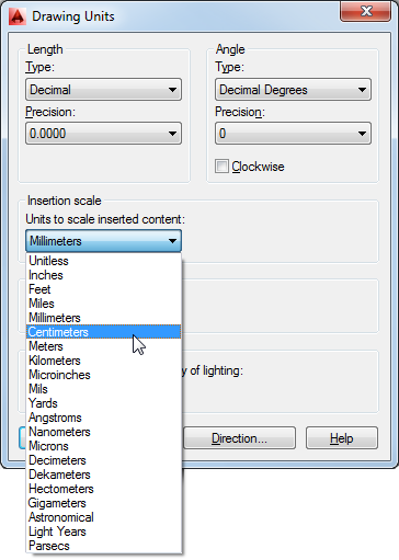
You may recall from Chapter 3, “Setting Up and Using the Drafting Tools,” that you have the opportunity to specify the type of units for which the drawing is set up in the Drawing Units dialog box under the Insertion Scale group. DesignCenter uses this information when you drag and drop blocks from DesignCenter into an open drawing. This is how DesignCenter is able to correctly scale a block drawn in metric to a drawing that is drawn in the Imperial format. The same option is offered in the Block Definition dialog box.
Blocks aren’t the only type of drawing component you can click and drag from the Palette view. Linetypes, layouts, dimension styles, and text styles can all be imported from files on your computer or network through DesignCenter’s Palette view.
Exchanging Data Between Open Files
You’ve seen how you can extract a block from a file stored on your hard disk and place it into an open drawing, but what if you want to copy a block from one open drawing to another open drawing? You change the way the Tree view displays data so that it shows only the files that are loaded in AutoCAD. The following exercise demonstrates how this works:
In this example, you inserted a block from one open drawing into another drawing. If you prefer to use the Insert dialog box, you can right-click the block name in step 6 and choose Insert Block. The Insert dialog box opens, enabling you to set the Insertion Point, Scale, and Rotation options.
Just as with drawings, you can see a preview and descriptive text for blocks below the Palette view. In Chapter 4, you had the option to save a preview image with the block when you first created a block. This is where that preview icon can be really helpful. The preview icon gives you a chance to see what the block looks like when you use DesignCenter to browse through your drawing files. If you don’t save a preview icon, you’ll see the same block icon that was displayed in the previous Palette view.
You can also add the text description at the time you create the block. Before saving the block, enter a description in the Description box of the Block Definition dialog box.
If you’re updating older drawing files to be used with DesignCenter, you can add text descriptions to blocks by using the Create tool in the Home tab’s Block panel or the Create Block tool in the Insert tab’s Block Definition panel. Click the Create tool and then, in the Block Definition dialog box, select the name of a block from the Name drop-down list. Enter the description you want for this block in the Description box toward the bottom of the Block Definition dialog box. When you’re finished, click OK.
Loading Specific Files into DesignCenter
You’ve seen how you can locate files through the Tree view and Palette view. If you already know the name and location of the file with which you want to work, you can use a file dialog box to open files in DesignCenter. Instead of choosing the Open tool on the Quick Access toolbar, you use the Load tool on the DesignCenter toolbar to open the Load dialog box. This is a standard file dialog box that lets you search for files on your computer or network.
If you want to open a file in DesignCenter that you’ve recently opened, you can use the History tab just above the Tree view. The Tree view closes, and you see a list of the files you’ve worked on most recently.
Customizing the Tool Palettes with DesignCenter
Many AutoCAD users have built their own custom library of symbols. In Chapter 1, “Exploring the Interface,” you saw how easy it is to drag and drop a symbol, known as a tool, from the tool palettes. At first glance, there is no obvious way to add your own tools to the palettes, but adding tools and additional palettes to the tool palettes is fairly simple once you’re familiar with DesignCenter. The following exercise shows you how it’s done:

You’ve just created a tool palette and added two symbols. You can continue to add symbols from other drawings to your custom tool palette. Or, if you have a drawing that contains all the blocks you need for a tool palette, you can quickly create a tool palette directly from a file. Here’s how that’s done:
This exercise showed that you can quickly create a palette of all the blocks from a file. You can do the same thing with entire folders of drawings, although you may want to make sure such folders don’t contain too many files.
But what if you don’t want some of the items in your custom palette? You can remove items easily by using the context menu:
You may have noticed the Cut and Copy options in the context menu in step 2. You can use these options to move symbols from one palette to another. For example, instead of deleting the three symbols in step 2, you can choose Cut from the context menu, open another palette, right-click, and choose Paste. The symbols move to the new palette location. In the next section, you’ll see how you can use the Copy and Paste context menu options to make a copy of a tool in the same palette.
Customizing a Tool
Other context menu options let you delete entire palettes or rename tools or palettes. You can also edit the properties of symbols in a palette. The following exercise shows how to use the context menu options to create two scale versions of the same tool:
Figure 27-31 The Tool Properties dialog box
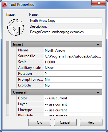
This exercise demonstrated that you can have multiple versions of a tool at different scales. You can then use the tool that’s appropriate to the scale of your drawing. As you can see from the Tool Properties dialog box, you can also modify other tool properties, such as color and layer assignments. You can use this feature to create sets of tools for different-scale drawings. For example, you can create a palette of architectural reference symbols for 1⁄4″-scale drawings, and you can create another palette for 1⁄8″-scale drawings.
Adding Hatch Patterns and Solid Fills
You’ve seen how you can turn blocks into tool palette tools, but what about solid fills? In Chapter 1, you learned that sample hatch patterns and solid fills are available in the tool palettes. Here’s how you can add your own:
In this exercise, you used the standard hatch patterns that come with AutoCAD. You can also create your own custom hatch patterns and import them to the tool palettes by using the method described here. See Chapter 26, “Customizing Toolbars, Menus, Linetypes, and Hatch Patterns,” for more information on creating custom hatch patterns.
If you want to set up a set of solid fill colors, you can do the following:
You can select any color, including colors from the True Color or Color Books tab in the Select Color dialog box that you learned about in Chapter 5, “Keeping Track of Layers and Blocks.” You can also cut and paste an existing solid fill tool to make copies. You can then modify the color property for each copy to get a set of custom solid fill colors.
Managing the Tool Palettes
You can perform other types of tool palette maintenance operations by using the Customize dialog box. For example, you can change the order of the tool palette tabs, or you can group tabs into categories that can be turned on or off. The following steps offer a glimpse of what you can do by showing you how to group palettes:
Figure 27-32 Customize dialog box for tool palettes
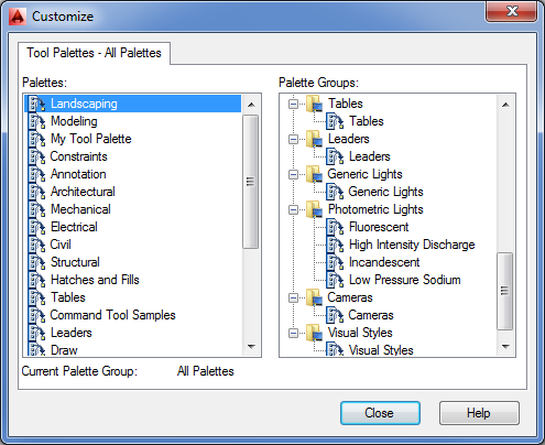
You’ve just created a new palette group and moved the two new palettes. You can view the palettes separately or all together:
You may have noticed that in the Properties menu, you also have the option to show just the new groups or all the palettes. This feature lets you keep the tabs in the tool palettes organized.
The list on the left side of the Customize dialog box also lets you change the order of the tabs by clicking and dragging the tab names up or down in the left panel. If you select a palette in the left panel and right-click, you can rename, delete, import, or export a palette.
DesignCenter and tool palettes offer great features that will prove invaluable to AutoCAD users. Although these examples show you how to use DesignCenter on a stand-alone computer, you can just as easily perform the same functions across a network or even across the Internet.
This ends our exploration of DesignCenter and tool palettes. In the next section, you’ll look at an AutoCAD feature that enables you to perform detailed searches in your hard drive for files and drawing elements.
Searching Your Drawing Library with Content Explorer
DesignCenter works well as a drawing management tool as long as you know where to look for your files. It’s great for current projects where you are editing and creating files daily. But what if you need to find drawings, blocks, hatch patterns, and other drawing elements from a long-forgotten past project? This is where Content Explorer™ can be a lifesaver.
Content Explorer has many features that overlap with DesignCenter, but Content Explorer places an emphasis on searching for data rather than relying on the user’s own file organization. But before you can begin to use Content Explorer, you’ll have to do a little setting up.
Indexing Your Files
Before you can put Content Explorer to use, you have to give it the location of your drawing files. Once you do that, it will look at the drawing files and catalog and index the data that it finds. If you have an extensive library of files, creating this index can take some time, but it occurs in the background so you don’t have to stop working. The index is stored as a database file, so when you perform a query, you don’t have to wait for a lengthy search to take place. If you’ve ever used a file-indexing program like Google Desktop, you’ll be familiar with how Content Explorer works.
To start Content Explorer and index a drive or folder, do the following:
Figure 27-33 The Explore tool and Content Explorer
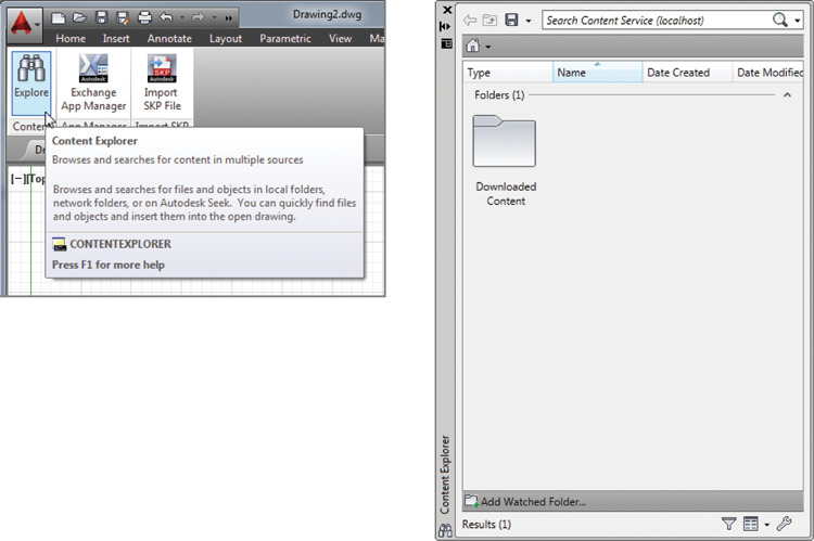
Figure 27-34 The Select Watched Folder dialog box
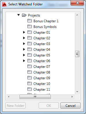
You’ll see a clock icon on the folder when you first add it to Content Explorer. This tells you that it is being indexed. As with DesignCenter, you can double-click on the folder to view its contents. If a file is displayed, you can double-click the file to view the elements that are available within the file.
Searching Your Files
The most powerful feature of Content Explorer is its ability to find an AutoCAD drawing or element by name. For example, suppose you remember that you created a block last year but you’ve forgotten the name and location of the drawing where the block was placed. Without Content Explorer, you’d have to make a best guess at the file location and just start hunting. This search could take hours. With Content Explorer’s search feature, you could find the block in minutes. Try the following to see firsthand how this can work. Note that you’ll have to wait until the indexing has finished from the previous exercise before the following exercise will work properly:
You can also click and drag the gate block into an open drawing or right-click on the block reference and select Go To Folder to open the folder containing the drawing. Other context menu commands include Explore, Open, Insert, Attach, and Properties.
If the item in the list is a drawing, you can double-click the drawing and its drawing elements will be listed in a way similar to the DesignCenter display.
Figure 27-35 The results of the gate search

Controlling Content Explorer’s Display
Content Explorer offers a few display options that are similar to the display options in Windows Explorer. Click the Change View Options arrowhead next to the Toggle Icon Size tool at the bottom of Content Explorer and you’ll see a list of options (see Figure 27-36). As you can see from the figure, you can select from a variety of sizes for the icons as well as the type of display.
Figure 27-36 The Toggle Icon Size display options

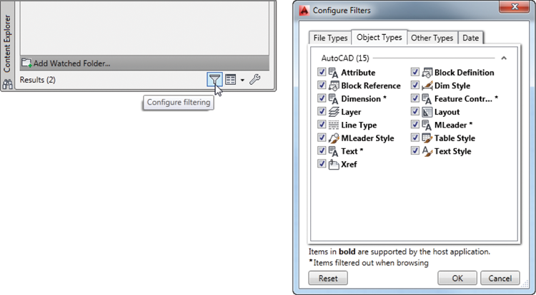
The Configure Filtering tool enables you to filter the contents of the display based on the type of drawing element you want to find. Click the Configure Filtering tool to open the Configure Filters dialog box (see Figure 27-37). In this dialog box, you can select the types of files and drawing objects to filter. For example, if you want to view only the blocks that a Content Explorer search has turned up, you can click the Object Types tab and then deselect all the types except for Block Definition and Block Reference. Content Explorer will display only blocks. You can also filter by date by selecting the Date tab at the top.
Figure 27-37 Configure Filtering icon (left) and the Configure Filters dialog box (right)
Adding Network Resources
If you use AutoCAD in an office with other AutoCAD users, you’ll want to install Content Explorer on your server where the AutoCAD drawings reside. You don’t have to install a full version of AutoCAD on the server. The part of Content Explorer that creates and maintains the index (the Content Service) can be installed on the server. The AutoCAD workstations will then be able to connect to the index that is created and maintained on the server.
To install the Content Service, start the AutoCAD installation on the server where your drawing files reside. At the main installation screen, select the Install Tools And Utilities option. In the Tools And Utilities window, make sure there is a check mark by the Autodesk Content Service option and deselect the other options. When you click Install, the Content Service will be installed.
You still need to make some additional setting changes after the Content Service is installed. From the Windows Desktop, choose Start ⇒ All Programs ⇒ Autodesk ⇒ Content Service ⇒ Content Service Console. In the Autodesk Content Service – Administration Console dialog box, click Add Watch Folder to add a folder to include in the indexing. The folder you wish to add must be a network shared folder.
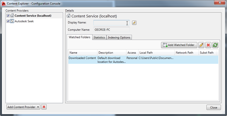
To connect to the Content Service index from a workstation, do the following:
Figure 27-38 The Content Explorer – Configuration Console dialog box
Besides searching network resources, you can use Content Explorer to search the Autodesk Seek site. Autodesk Seek is a website where you can find prebuilt drawing files and other resources. To search the Seek site, click the arrowhead next to the Home icon in the upper-left corner of the Content Explorer window and select Autodesk Seek. The Home icon will change to the Seek icon to indicate that your searches will take place there.
Establishing Office Standards
Communication is especially important when you’re one of many people working on the same project on separate computers. A well-developed set of standards and procedures helps to minimize problems that may be caused by miscommunication. In this section, you’ll find some suggestions for setting up these standards.
Establishing Layering and Text Conventions
The issue of CAD standards has always been difficult to resolve. Standardizing layers, dimensions, and text can go a long way toward making file exchange more seamless between different trades, and standards can also make files easier to understand. When everyone follows a standard, the structure of a drawing is more easily understood, and those who have to edit or interpret your work can do so without having to ask a lot of questions.
You’ve seen how layers can be a useful tool. But they can easily get out of hand when you have free rein over their creation and naming. Users may become confused while attempting to isolate or identify objects and layers in a drawing they’re not familiar with. Inconsistent layer naming can also inhibit the use of timesaving tools like the Layer Translator (covered later in this chapter), AutoLISP routines, and script files that might otherwise be able to automate many repetitive tasks. With an appropriate layer-naming convention, you can minimize this type of problem (although you may not eliminate it entirely). A too-rigid naming convention can cause as many problems as no convention at all, so it’s best to give general guidelines rather than force everyone to stay within narrow limits. As mentioned in Chapter 5, you can create layer names in a way that enables you to group them by using wildcards. AutoCAD allows up to 255 characters in a layer name, so you can use descriptive names.
Lineweights should be standardized in conjunction with colors. If you intend to use a reprographics service for your plotting, check with them first; they may require that you conform to their color and lineweight standards.
Checking Office Standards

AutoCAD offers an open-ended environment that lends itself to easy customization, but this also leaves the door wide open for on-the-fly creation of layer names, dimension styles, and other drawing format options. It’s easy to stray from standards, especially when you’re under pressure to get a project out on a deadline. To help you and your office maintain a level of conformity to office or industry standards, AutoCAD includes the Standards command.
The Standards command lets you quickly compare a drawing against a set of standard layer names, dimension style settings, linetypes, and text styles. A dialog box displays any item that doesn’t conform to the standards you selected. You can then adjust the file to make it conform to your standards.
You can create several sets of standards for different types of files, and you can assign the standards directly to a file so that anyone editing that file can make periodic checks against your office standards while the drawing is being edited.
The Standards command discussed here isn’t available in the Autodesk® AutoCAD LT® software.
Setting Up Standards Files
The first step in using the Standards command is to set up a file to which other drawing files can be compared. This standards file will be an AutoCAD drawing file with a .dws filename extension. Here are the steps to create a new DWS standards file:
As an alternative to creating a new file, you can open an existing file that contains all the typical settings you’ll want to use on your projects. You can then delete all the graphics in the file and purge all its blocks and shapes. After you’ve done this, you can begin at step 3 of the previous exercise to save the file as a DWS standards file.
You can set up as many DWS files as you need for your office. Often, a single set of standards is too limiting if your office is involved in a diverse range of projects, so you may want to set up DWS files on a project basis, drawing on a core of generic DWS files.
Using the Standards Command to Associate Standards
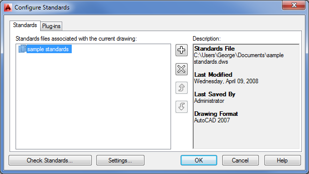
After you’ve created your DWS standards files, you can begin to check other files for conformity. The next task is to assign your DWS file to the drawing file that you want to check:
Figure 27-39 Associating a set of standards with a file
If AutoCAD finds a discrepancy between the standards file and the current file, a description of the problem appears at the top of the dialog box. For example, if the name of a dimension style that isn’t in the standards file appears in the current file, a message appears indicating that a nonstandard dimension style exists in the current drawing. If this happens, take the following steps:
You can check Mark This Problem As Ignored if you want the Check Standards dialog box to ignore the problem in future standards-checking sessions.
In this example, you entered the Check Standards dialog box directly from the Configure Standards dialog box. After you’ve used the Check Standards dialog box on a file, the DWS standards file is associated with the checked file. You can go directly to the Check Standards dialog box by choosing Manage ⇒ CAD Standards ⇒ Check during any subsequent editing session.
Checking Standards for Multiple Drawings
The Standards and Check Standards commands are great for checking individual files, but eventually you’ll want a method to batch-check a set of files. AutoCAD 2014 provides a utility that does just that. The Batch Standards Checker is a stand-alone utility that audits a set of drawing files and checks them against their associated DWS files. The Batch Standards Checker can also check a set of drawings against a single DWS file of your choice. It then generates an audit report showing any problems it encounters.
Here’s how it works:
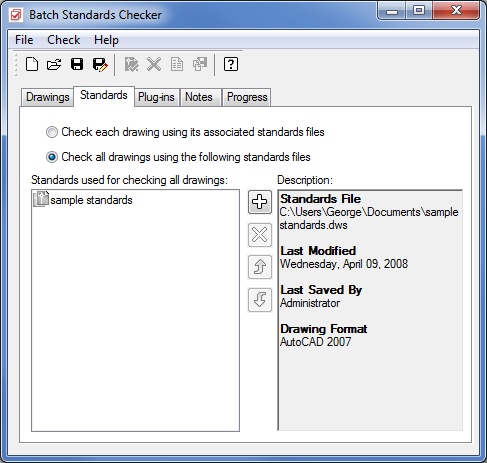
Figure 27-40 The Batch Standards Checker dialog box
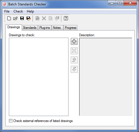
Figure 27-41 Choose the files you want to check.
AutoCAD proceeds to check each file listed in the Drawings tab list box. The progress is shown in the Progress tab of the Batch Standards Checker dialog box. If you decide to cancel the audit, you can click the Stop Check button, which cancels the audit currently in progress. When files are being checked, the Stop Check button turns red.
When all the files have been checked, the data from the audit is automatically saved in the check file you created in step 7. Then the audit file is opened in your web browser and you see the results of the audit.
The audit report file displays a number of options in a set of radio buttons:
Reviewing Previously Saved Standards Audits
After you’ve created a check file and completed a standards audit, you can always return to the audit by opening the Batch Standards Checker utility and clicking the Open tool in the toolbar.
This opens the Batch Standards Checker file open dialog box, where you can locate and open a previously saved standards check file with the .chx filename extension. In this file, you see a list of the files that were checked in the Drawings tab and the DWS standards file used in the Standards tab.
You can then view the results of the audit by clicking the View Report tool in the toolbar. This opens a web browser and displays the audit results contained in the standards check file.
Converting Multiple Layer Settings
As AutoCAD files flow in and out of your office, you’re likely to find yourself working with layering standards from another system. You might, for example, receive files from an architect who uses the CSI standard for layer names, whereas your office prefers the AIA standard. If your job involves extensive reworking of such files, you’ll want to change the layering system to one with which you’re most familiar. But converting layer settings is a painstaking and time-consuming process, especially if several files need conversion.
Fortunately, AutoCAD offers a tool that can make layer conversion from one standard to another much easier. The Layer Translator lets you map nonstandard layers (that is, those using a system different from your own) to your own set of standards. It can then convert those layers to match your office standards. After you’ve mapped a set of layers between two files, you can save the map settings in a drawing file. Then any other files you receive that contain the same nonstandard layer settings can be converted to your own layer standards quickly. Let’s take a closer look at how the Layer Translator works.
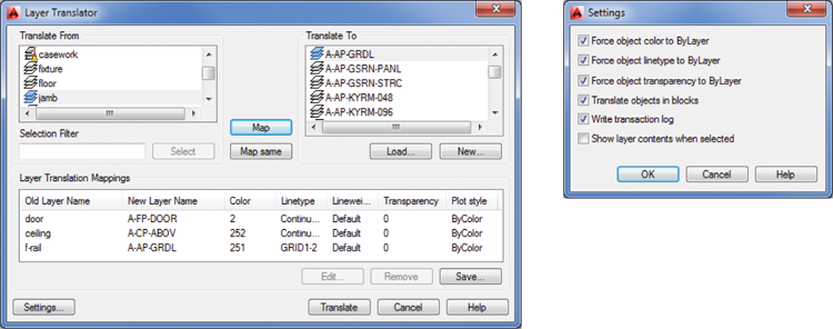
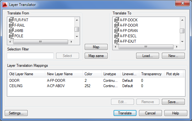
When using the Layer Translator, you must initially match the layers of your incoming file with those of a file whose layers are set up the way you want. Here are the steps to do this:
Figure 27-42 The Layer Translator dialog box
After you’ve completed your layer mapping, you can save the mapping for future use:
After you’ve saved the layer mapping in step 2, you can load the saved layer map settings into the Layer Translator dialog box in future layer translations. This saves you the effort of mapping each layer individually each time you want to perform a translation. This will work for incoming files that use the same layer settings, but you’ll have to create another layer map settings file for each different layer system you encounter.
To use a saved layer map, click the Load button in the Translate To group of the Layer Translator dialog box and then select the layer map file you saved in step 2. You can have several layer map files for each project involving files with nonstandard layer settings.
Exploring Other Layer Translator Options
You’ll often come across situations in which the layers in the Translate From list don’t correspond directly to those in the Translate To list. For these situations, the Layer Translator offers a few additional options.
If you have difficulty finding a match for layers in the Translate From list, you can create a new layer by clicking the New button in the Translate To group. This opens the New Layer dialog box (see Figure 27-43) in which you can enter the properties for your new layer.
Figure 27-43 Creating a new layer
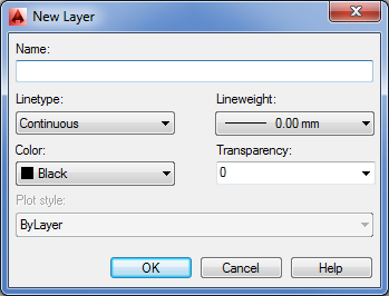
After you create a new layer with this dialog box, it appears in the Translate To list box, enabling you to map Translate From layers to your new layer.
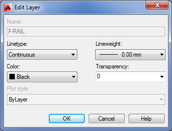
Another option you’ll find useful is the Edit button in the Layer Translation Mappings group. You may find that after you’ve mapped a Translate From layer to a Translate To layer, the Translate To layer isn’t exactly what you want. You can highlight the mapped layer in the Layer Translation Mappings group list box and then click Edit to open the Edit Layer dialog box (see Figure 27-44). From here, you can modify the new layer’s settings from their original values.
Figure 27-44 Changing a layer’s properties
Finally, the Layer Translator offers a set of options that give you some control over the way translations are performed. For example, you can control whether layer colors and linetypes are forced to the ByLayer setting or whether layer assignments for objects in blocks are translated. You can access these options by clicking the Settings button in the lower-left corner of the Layer Translator dialog box. Figure 27-45 shows the Settings dialog box. The options are self-explanatory.
Figure 27-45 The Layer Translator and its Settings dialog box