Chapter 15
Advanced Editing and Organizing
Because you may not know all of a project’s requirements when it begins, you usually base the first draft of a design on anticipated needs. As the plan goes forward, you adjust for new requirements as they arise. As more people enter the project, additional design restrictions come into play, and the design is further modified. This process continues throughout the project, from the first draft to the end product.
In this chapter, you’ll gain experience with some tools that will help you edit your drawings more efficiently. You’ll take a closer look at Xrefs and how they may be used to help streamline changes in a drawing project. You’ll also be introduced to tools and techniques you can use to minimize duplication of work, such as the Quick Select tool and the QuickCalc feature. The AutoCAD® 2014 software can be a powerful timesaving tool if used properly. This chapter examines ways to harness that power.
In this chapter, you will learn to:
- Use external references (Xrefs)
- Manage layers
- Use advanced tools: Filter and Quick Select
- Use the QuickCalc calculator
Using External References
Chapter 7, “Mastering Viewing Tools, Hatches, and External References,” mentioned that careful use of blocks, external references (Xrefs), and layers can help improve your productivity. In the following sections, you’ll see firsthand how to use these features to help reduce design errors and speed up delivery of an accurate set of drawings. You do so by controlling layers in conjunction with blocks and Xrefs to create a common drawing database for several drawings. You can also use AutoCAD DWF and Acrobat PDF files as Xrefs. See Chapter 14, “Copying Existing Drawings from Other Sources,” for more on PDF files and Chapter 27, “Managing and Sharing Your Drawings,” for more on DWF files.
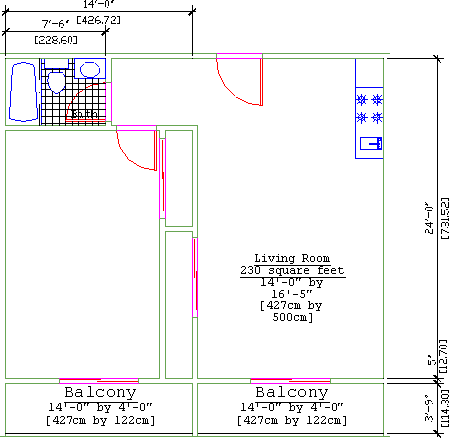
Later, you’ll start to use Xrefs to create different floor plans for the building you worked on earlier in this book. To save you some time, we’ve created a second one-bedroom unit plan called Unit2 that you’ll use in these exercises (see Figure 15-1). You can find this new unit plan in the Chapter 15 folder of sample files.
Figure 15-1 The one-bedroom unit
Preparing Existing Drawings for External Referencing
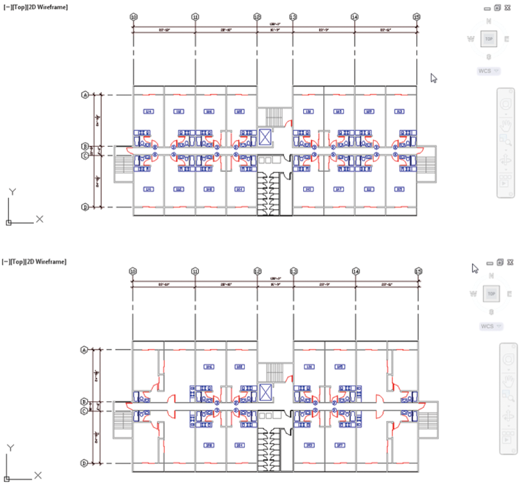
Chapter 7 discussed how you can use Xrefs to assemble one floor of the apartment. In this section, you’ll explore the creation and use of Xrefs to build multiple floors, each containing slightly different sets of drawing information. By doing so, you’ll learn how Xrefs enable you to use a single file in multiple drawings to save time and reduce redundancy. You’ll see that by sharing common data in multiple files, you can reduce your work and keep the drawing information consistent.
You’ll start by creating the files that you’ll use later as Xrefs:
Figure 15-2 The overall plan
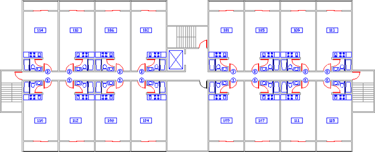
Figure 15-3 Units to be exported to the Floor1 file

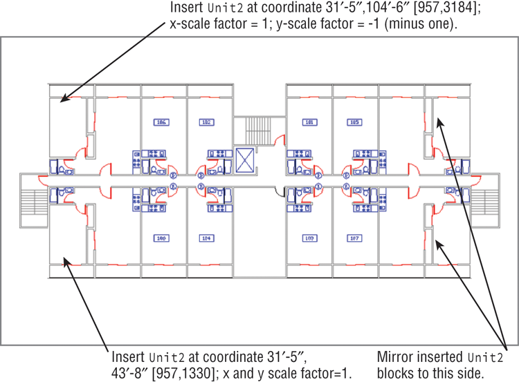
Figure 15-4 Insertion information for Unit2. Metric coordinates are shown in brackets.
You’ve just created three files: Floor1, Floor2, and Common. Each file contains unique information about the building. Next, you’ll use the Xref command to recombine these files for the different floor plans in your building.
Assembling Xrefs to Build a Drawing
You’ll now create composite files for each floor using Xrefs of only the files needed for the individual floors. You’ll use the Attach option of the Xref command to insert all the files you exported from the Plan file.
Follow these steps to create a file representing the first floor:
The drawing may appear faded. This is because AutoCAD has a feature that allows you to fade an Xref so that it is easily distinguished from other objects in your current drawing. You can quickly change the reference fade setting by doing the following:
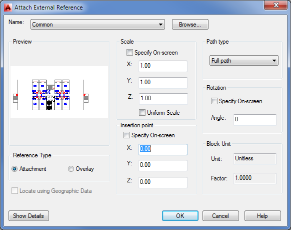
Figure 15-5 The Attach External Reference dialog box
Your Xref should now appear solid. Remember the Xref Fading slider; you may find that you’ll need it frequently when working with Xrefs.
Now continue to add some reference files:
Next, use the current file to create another file representing a different floor:
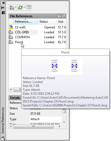
Figure 15-6 Highlight Floor1 in the list of Xrefs.
Now when you need to make changes to Xref-1 or Xref-2, you can edit their individual Xref files. The next time you open Xref-1 or Xref-2, the updated Xrefs will automatically appear in their most recent forms.
Xrefs don’t need to be permanent. As you saw in the previous exercise, you can attach and detach them easily at any time. This means that if you need to get information from another file—to see how well an elevator core aligns, for example—you can temporarily attach the other file as an Xref to check alignments quickly and then detach it when you’re finished.
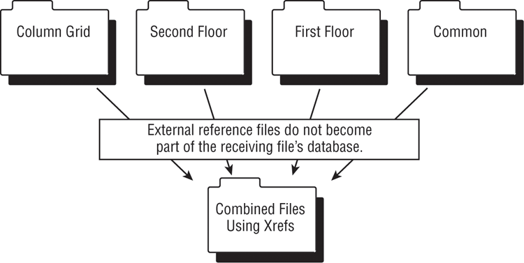
Think of these composite files as final plot files that are used only for plotting and reviewing. You can then edit the smaller, more manageable Xref files. Figure 15-7 illustrates the relationship of these files.
Figure 15-7 A diagram of Xref file relationships
The combinations of Xrefs are limited only by your imagination.
Updating Blocks in Xrefs
Several advantages are associated with using Xref files. Because the Xrefs don’t become part of the drawing file’s database, the referencing files remain small. Also, because Xref files are easily updated, work can be split up among several people in a workgroup environment or on a network. For example, for your hypothetical apartment building project, one person can be editing the Common file while another works on Floor1, and so on. The next time the composite Xref-1.dwg or Xref-2.dwg file is opened, it automatically reflects any new changes made in the Xref files. If the Xref is updated while you still have the receiving file open, you see a balloon message telling you that an Xref requires a reload.
Let’s see how to set this up:
Figure 15-8 The Common file with the revised unit plan
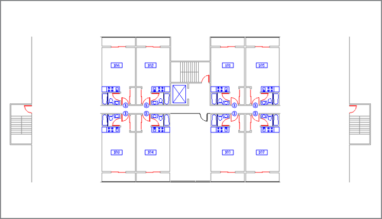
Figure 15-9 The utility room inserted
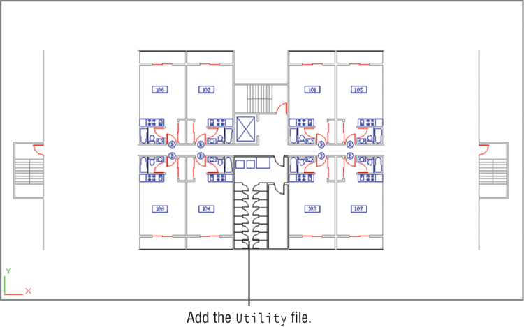
Figure 15-10 The Xref-1 and Xref-2 files with the units updated
Importing Named Elements from Xrefs
Chapter 5, “Keeping Track of Layers and Blocks,” discussed how layers, blocks, linetypes, and text styles—called named elements—are imported along with a file that is inserted into another file. Xref files don’t import named elements. You can, however, review their names and use a special command to import the ones you want to use in the current file.
AutoCAD renames named elements from Xref files by giving them the prefix of the filename from which they come. For example, the Wall layer in the Floor1 file is called Floor1|WALL in the Xref-1 file; the Toilet block is called Floor1|TOILET. You can’t draw on the layer Floor1|WALL, nor can you insert Floor1|TOILET, but you can view Xref layers in the Layer Properties Manager dialog box, and you can view Xref blocks by using the Insert dialog box.
Next, you’ll look at how AutoCAD identifies layers and blocks in Xref files, and you’ll get a chance to import a layer from an Xref:
Figure 15-11 The Xbind dialog box
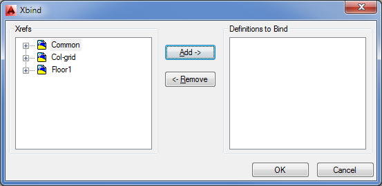
Figure 15-12 The expanded Floor1 list
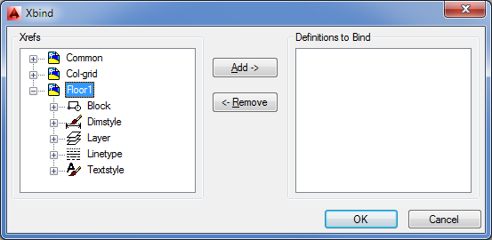
Figure 15-13 The expanded Layer list
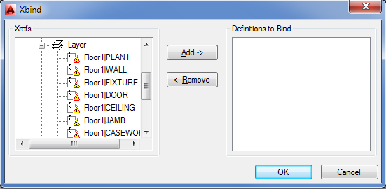
As you can see, when you use Xbind to import a named item, such as the Floor1|WALL layer, the vertical bar (|) is replaced by two dollar signs surrounding a number, which is usually 0. (If for some reason the imported layer name Floor1$0$WALL already exists, the 0 in that name is changed to 1, as in Floor1$1$WALL.) Other named items are renamed in the same way, using the $0$ replacement for the vertical bar.
You can also use the Xbind dialog box to bind multiple layers as well as other items from Xrefs attached to the current drawing. You can bind an entire Xref to a drawing, converting it to a simple block. By doing so, you have the opportunity to maintain unique layer names of the Xref being bound or to merge the Xref’s similarly named layers with those of the current file. See Chapter 7 for details.
Controlling the Xref Search Path
One problem AutoCAD users encountered in the past was lost or broken links to an Xref. This occurs when an Xref file is moved from its original location or when you receive a set of drawings that includes Xrefs. The Xref links are broken because AutoCAD doesn’t know where to look.
When you insert an Xref, the Attach External Reference dialog box opens, offering you options for insertion point, scale, and rotation. This dialog box also provides the Path Type option, which enables you to select a method for locating Xrefs. You can choose from three path type options:
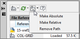
You can change the path type using two features in the External References palette. First, select the Xref or Xrefs you want to change, then right-click and select Path in the context menu. You will see three options: Make Absolute, Make Relative and Remove Path. Select the option you desire for the selected Xrefs. You can also click the Change Path tool in the External References palette toolbar.
Managing Layers
In a survey of AutoCAD users, Autodesk discovered that one of the most frequently used features in AutoCAD is the Layer command. You’ll find that you turn layers on and off to display and edit the many levels of information contained in your AutoCAD files. As your files become more complex, controlling layer visibility becomes more difficult. Fortunately, AutoCAD offers the Layer States Manager to make your work a little easier.
Saving and Recalling Layer Settings
The Layer States Manager lets you save layer settings. This can be crucial when you’re editing a file that serves multiple uses, such as a floor plan and reflected ceiling plan. You can, for example, turn layers on and off to set up the drawing for a reflected ceiling plan view and then save the layer settings. Later, when you need to modify the ceiling information, you can recall the layer settings to view the ceiling data.
The following steps show you how the Layer States Manager works:
Figure 15-14 The view of the 15b-unit.dwg file before and after changing layer settings
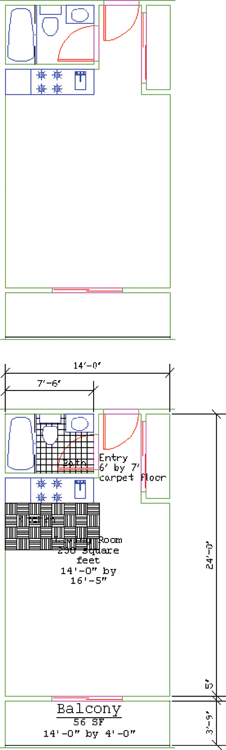
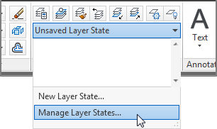
Figure 15-15 The Layer States Manager dialog box

Figure 15-16 The New Layer State To Save dialog box
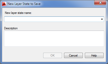
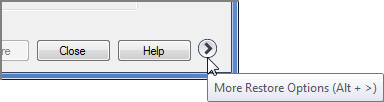
Figure 15-17 The More Restore Options button
You’ve just saved a layer state and then changed the layer settings to something different from the saved state. The following steps demonstrate how you can restore the saved layer state:
The layer states are saved with the file so that you can retrieve them at a later date. As you can see in the Layer States Manager dialog box, you have a few other options, as shown in Table 15-1.
Table 15-1: Layer States Manager dialog box options
| Option | Purpose |
| New | Creates a new layer state. |
| Save | Saves the selected layer state after edits. |
| Edit | Lets you edit the layer settings for the selected layer state. |
| Rename | Renames a selected layer state. |
| Delete | Deletes a layer state from the list. |
| Import | Imports a set of layer states that have been exported using the Export option of this dialog box. |
| Export | Saves a set of layer states as a file. By default, the file is given the name of the current layer state with the .las filename extension. You can import the layer-state file into other files. |
| Layer Properties To Restore (in the expanded dialog box) | Lets you select the layer properties to be controlled by the Layer States Manager. |
In addition to saving layer states by name, you can quickly revert to a previous layer setting by clicking the Previous tool on the Home tab’s Layers panel. This tool enables you to revert to the previous layer settings without affecting other settings in AutoCAD. Note that Previous mode doesn’t restore renamed or deleted layers, nor does it remove new layers.
After you become familiar with these layer-state tools, you’ll find yourself using them frequently in your editing sessions.
Other Tools for Managing Layers
There are quite a number of tools that help you quickly set up layers as you work. In the following sections, you’ll learn about some of those other tools you’ve seen in the Layers panel. All the tools discussed in these sections have keyboard command equivalents. Check the tool tip for the keyboard command name when you select one of these tools from the Layers panel.
Using Layer Walk to Explore Layers
When you work with a file that was produced by someone else, you usually have to spend some time becoming familiar with the way layers are set up in it. This process can be tedious, but the Layer Walk tool can help.
As the name implies, the Layer Walk tool lets you “walk through” the layers of a file, visually isolating each layer as you select its name from a list. You can use Layer Walk to select the layers that you want visible, or you can turn layers on and off to explore a drawing without affecting the current layer settings. To open the LayerWalk dialog box, do the following:
Figure 15-18 The LayerWalk dialog box
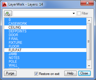
You can click and drag the bottom edge of the dialog box to expand the list so that you can see all the layers in the drawing. When you first open the LayerWalk dialog box, you see the current visible layers selected. Layers that are off aren’t selected. Click a single layer and AutoCAD displays just that layer. With a single layer selected, you can “walk” through the layers by pressing the down and up arrow keys.
You can use this dialog box to set up layer settings visually by Ctrl+clicking layer names to make them visible. Turn off Restore On Exit to maintain the layer settings you set up in the LayerWalk dialog box, or turn it on if you want the drawing to revert to the layer settings that were in place before you opened the LayerWalk dialog box. Right-click the list of layers to display a set of other options that let you save the layer state and invert the selection.
Changing the Layer Assignment of Objects
In addition to the Layer Walk tool, the Layers panel includes two tools that change the layer assignments of objects: the Match tool and the Change To Current Layer tool on the expanded Layers panel.
The Match tool is similar to the Match Properties tool, but it’s streamlined to operate only on layer assignments. After clicking this tool in the Layers panel, select the object or objects you want to change, press ↵, and then select an object whose layer you want to match.
The Change To Current Layer tool on the expanded Layers panel changes an object’s layer assignment to the current layer.
Controlling Layer Settings Through Objects
The remaining Layer tools let you make layer settings by selecting objects in the drawing. These tools are easy to use: click a tool, and then select an object.
The following list describes each tool:
Merging Multiple Layers Into One Layer
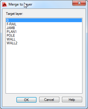
If you find that you have several layers that you want to merge into one layer, you can use the Merge option in the Layer Manager. You can merge a single layer or a set of layers into an existing layer, other than one that has been selected. If the layer you want to use for the merge does not exist, create it first. Then in the Layer Manager, select the layer or layers you want to merge, right-click and select the Merge Selected Layer(s) To… option. The Merge To Layer dialog box appears (see Figure 15-19). You can select the layer name from the list. The merged layers are automatically purged from the drawing.
Figure 15-19 The Merge To Layer dialog box
Using Advanced Tools: Filter and Quick Select
Two other tools are extremely useful in your day-to-day work with AutoCAD: selection filters and Quick Select. We’ve saved the discussion of these tools until this part of the chapter because you don’t need them until you’ve become accustomed to the way AutoCAD works. Chances are that you’ve already experimented with some of the AutoCAD menu options not yet discussed in the exercise. Many of the drop-down menu options and their functions are self-explanatory. Selection filters and QuickCalc (the latter is discussed later in this chapter) don’t appear in any of the menus and require further explanation.
Let’s start with selection filters. AutoCAD includes two selection-filtering tools: The Quick Select tool offers a quick way to locate objects based on their properties. The Filter tool lets you select objects based on a more complex set of criteria.
Filtering Selections
Suppose you need to isolate just the walls of your drawing in a separate file. One way to do this is to turn off all the layers except the Wall layer. You can then use the Wblock command and select the remaining walls, using a window to write the wall information to a file. Filters can simplify this operation by enabling you to select groups of objects based on their properties.
Follow these steps to select objects based on their layer assignment:
Figure 15-20 The Object Selection Filters dialog box
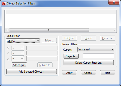
In this exercise, you filtered out a layer by using the Filter command. After you designate a filter, you then select the group of objects through which you want AutoCAD to filter. AutoCAD finds the objects that match the filter requirements and passes those objects to the current command.
As you’ve seen from the previous exercise, you can choose from many options in this utility. Let’s take a closer look.
Working with the Object Selection Filters Dialog Box
To use the Object Selection Filters dialog box, first select the criterion for filtering from the drop-down list. If the criterion you select is a named item (layer, linetype, color, or block), you can then click the Select button to choose specific items from a list. If there is only one choice, the Select button is dimmed.
After you’ve determined what to filter, you must add it to the list by clicking the Add To List button. The filter criterion then appears in the list box at the top of the Object Selection Filters dialog box, and you can apply that criterion to your current command or to a later command. AutoCAD remembers your filter settings, so if you need to reselect a filtered selection set, you don’t have to redefine your filter criteria.
Saving Filter Criteria
If you prefer, you can preselect filter criteria. Then, at any Select objects: prompt, you can type Filter↵, highlight the appropriate filter criteria in the list box, and click Apply. The specifications in the Object Selection Filters dialog box remain in place for the duration of the current editing session.
You can also save a set of criteria by entering a name in the input box next to the Save As button and then clicking the button. The criteria list data is saved in a file called Filter.nfl in the C:UsersUser NameAppDataRoamingAutodeskAutoCAD 2014R19.1enuSupport folder. You can access the criteria list at any time by opening the Current drop-down list and choosing the name of the saved criteria list.
Filtering Objects by Location
Notice the X, Y, and Z drop-down lists just below the main Select Filter drop-down list in the Object Selection Filters dialog box. These lists become accessible when you select a criterion that describes a geometric property or a coordinate (such as an arc’s radius or center point). You can use these lists to define filter selections even more specifically, using greater than (>), less than (<), equal to or greater than (>=), equal to or less than (<=), equal to (=), or not equal to (!=) (called relational operators).
For example, suppose you want to grab all the circles whose radii are greater than 4.0 units. To do this, choose Circle Radius from the Select Filter drop-down list. Then, in the X list, select >. Enter 4.0 in the input box to the right of the X list, and click Add To List. The items
Circle Radius > 4.0000
Object = Circle
are added to the list box at the top of the dialog box. You used the > operator to indicate a circle radius greater than 4.0 units.
Creating Complex Selection Sets
At times, you’ll want to create a specific filter list. For instance, say you need to filter out all the Door blocks on the layer Floor2 and all arcs with a radius equal to 1. To do this, you use the grouping operators found at the bottom of the Select Filter drop-down list. You’ll need to build a list as follows:
** Begin OR
** Begin AND
Block Name = Door
Layer = Floor2
** End AND
** Begin AND
Entity = Arc
Arc Radius = 1.0000
** End AND
** End OR
Notice that the Begin and End operators are balanced; that is, for every Begin OR or Begin AND, there is an End OR or End AND.
This list may look simple, but it can get confusing. If criteria are bounded by the AND grouping operators, objects must fulfill both criteria before they’re selected. If criteria are bounded by the OR grouping operators, objects fulfilling either criteria will be selected. If you add the wrong option accidentally, select it from the list and click the Delete button. If you need to insert an option in the middle of the list, select the item that comes after the item you want to insert, and then select and add the item.
Here are the steps to build the previous list:
If you make an error in any step, highlight the item, select an item to replace it, and click the Substitute button instead of the Add To List button. If you need only to change a value, click the Edit Item button near the center of the dialog box.
Using Quick Select
The Filter command offers a lot of power in isolating specific types of objects, but in many situations you may not need such an elaborate tool. The Qselect dialog box can filter your selection based on the object properties, which are the more common filter criteria. To access the Qselect dialog box, click Quick Select in the Home tab’s Utilities panel, or right-click the drawing area when no command is active and choose Quick Select from the context menu.
Quick Select is also offered as an option in a few other dialog boxes. Try using the Wblock command again, this time using the Quick Select option offered in its dialog box:
Figure 15-21 The Quick Select dialog box
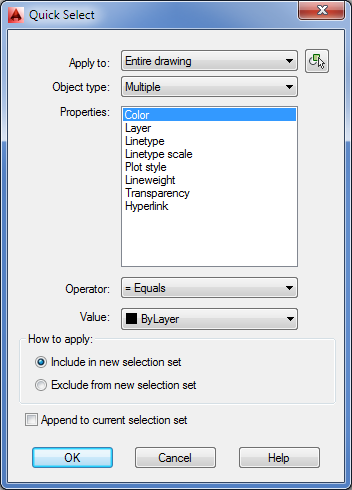
The Qselect command selects objects based on their properties, as shown in the Properties list box. You can apply the selection criteria based on the entire drawing, or you can use the Select Objects button in the upper-right corner of the dialog box to isolate a set of objects to which you want to apply the selection criteria.
In the previous exercise, you used Quick Select from within another dialog box. As mentioned earlier, you can also use Quick Select by clicking Quick Select in the Home tab’s Utilities panel or by right-clicking the drawing area when no command is active and choosing Quick Select from the context menu. Quick Select then uses the Noun/Verb selection method: You select objects using Quick Select first, and then you apply editing commands to the selected objects.
If you want to use Quick Select with a command that doesn’t allow the Noun/Verb selection method, you can select objects by using Quick Select, start the command you want to use, and then use the Previous Selection option.
Here is a description of the Quick Select dialog box options:
Using the QuickCalc Calculator
You may have noticed a calculator icon in some of the options in the Properties palette or in the right-click context menu. This is the QuickCalc tool. If you click it, you’ll see the QuickCalc calculator, shown in Figure 15-22. At first glance, it looks like a typical calculator. It has the standard math as well as the scientific functions that are available when you click the More button. If your view of QuickCalc doesn’t look like Figure 15-22, click the More/Less button and then expand the Number Pad or Scientific section by clicking the arrow in the title bar. You’ll also see a section for converting units, which comes in handy when you want to find the metric equivalent of an Imperial measurement.
Figure 15-22 QuickCalc and its parts
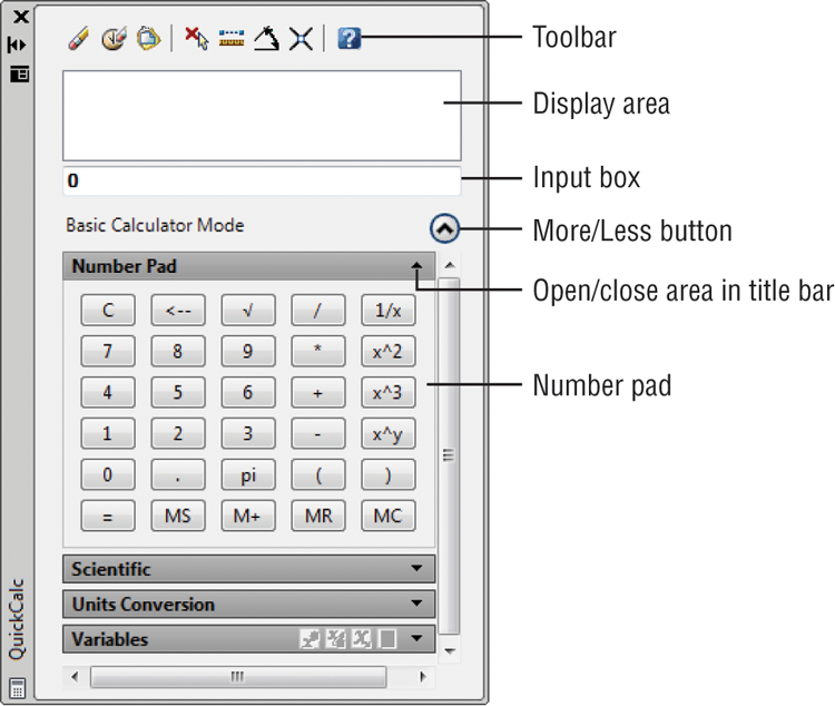
At the bottom is a section for variables. This area lets you store custom formulas and values to which you want to refer frequently.
Near the top is the display area. This is where QuickCalc keeps a running record of your calculation results. It also allows you to recall both the results and formulas you’ve used. Just below the display area is the input box. As you type, or as you click the keys of QuickCalc, your input appears in this box. Pressing Enter displays the resulting value both in the input box and in the display area.
Above the display area is a set of tools. These tools let you obtain other types of data from the drawing, such as the coordinate of a point or the intersection of two lines (see Figure 15-23).
Figure 15-23 The QuickCalc tools
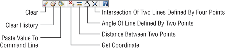
The function of these tools will become clearer as you become familiar with QuickCalc. Table 15-2 describes each tool. Next, you’ll get a chance to try out QuickCalc on some typical AutoCAD tasks.
Table 15-2: QuickCalc tools
| Tool | Purpose |
| Clear | Clears the value from the input box. |
| Clear History | Clears the display area. |
| Paste Value To Command Line | Pastes data from the input box to the command line. |
| Get Coordinates | Temporarily closes QuickCalc and prompts you to pick a point or points. Coordinates of the point or the angle value are placed in the input area. |
| Distance Between Two Points | Temporarily closes QuickCalc and prompts you to enter a point. Select two points; the distance between the points is placed in the input area of QuickCalc. |
| Angle Of Line Defined By Two Points | Returns the angle of two points. |
| Intersection Of Two Lines Defined By Four Points | Returns the coordinate of the intersection of four points. |
Adding Foot and Inch Lengths and Finding the Sum of Angles
Although QuickCalc may look simple, it provides a powerful aid in your work in AutoCAD. Besides offering the typical calculator functions, QuickCalc also lets you quickly add and subtract angle values, feet-and-inches lengths, and much more. You can paste the results from calculations into the command line so that you can easily include results as part of command-line responses.
To get a full appreciation of what QuickCalc can do for you, try the following exercises.
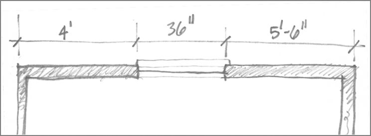
Imagine that you have a renovation project for which someone has taken dimensions in the field. You may be asked to draw a section of wall for which the overall dimension isn’t given, but portions of the wall are dimensioned in a sketch, as shown in Figure 15-24.
Figure 15-24 A sketch of measurements taken from an existing building
You can use QuickCalc to add a series of feet-and-inches dimensions:
Figure 15-25 The QuickCalc input box

Notice that you only had to enter the foot (′) sign. QuickCalc assumes that a value is in inches unless you specify otherwise. You can also enter distances in the more traditional way using dashes and zeros, as in 4′-0″ or 5′-6″. QuickCalc ignores the dashes.
Now, suppose you want to use your newfound length to draw a line. You can quickly add the results from the input box to the command line, as shown in the following exercise:
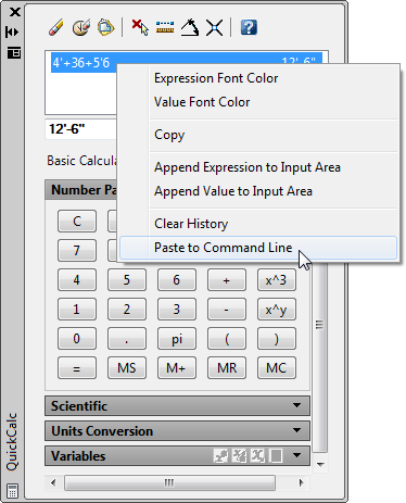
In this example, you used the Paste Value To Command Line tool in the QuickCalc toolbar. If you want to use a value that has scrolled up in the display area, you can select that value, right-click, and choose Paste To Command Line (see Figure 15-26).
Figure 15-26 The Paste To Command Line option in the context menu
This approach is especially useful when you’ve used QuickCalc to add several strings of dimensions and you need to recall them individually from the display area. In addition to adding feet and inches, you can perform other math functions, such as dividing a length by 2 or multiplying a length. If the input value is in feet and inches, the resulting value is returned in feet and inches. For example, if you divide 25′ by 6, the result is 4′-2″.
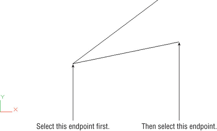
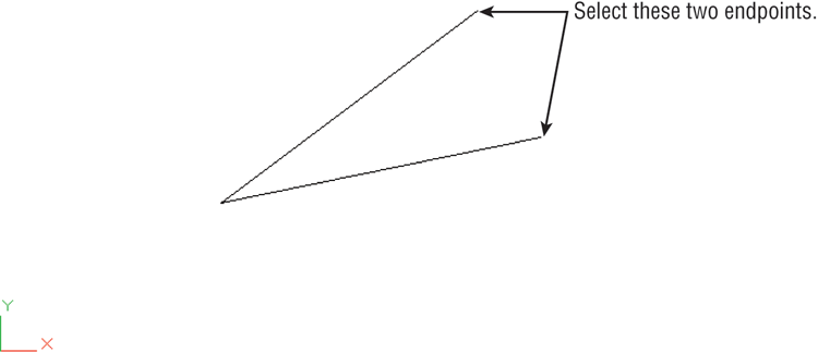
Another useful QuickCalc tool is Angle Of Line Defined By Two Points, which allows you to obtain the angle defined by two points:
Figure 15-27 Select these endpoints using the Angle Of Line Defined By Two Points option.
Here you added the angle of two lines, but you could just as easily have subtracted one angle from another or multiplied the value of a single angle. This can be useful if you need to find a fraction or a multiple of an angle. For example, you might need to find one-quarter of the angle described by a line, or you might want to find the angle that bisects two lines. You can do so by adding the value of two angles, as described in the exercise, and then dividing by 2 using the number pad or by including /2 in the input box. Once you’ve obtained a value, you can paste it into the command line while specifying angles for drawing input.
Using the Display Area and Units Conversion
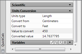
In addition to performing math functions on distances and angles, you can do some basic unit conversions. QuickCalc performs length, area, volume, and angle conversions in its Units Conversion group. Try the following exercise to learn how to convert a length from centimeters to feet and inches. In the process, you’ll also learn how you can move a value from the Units Conversion area to the QuickCalc input box.
Suppose you have a paper drawing that was done in metric and you need to turn it into an AutoCAD drawing in feet and inches. Here’s an example of how you can convert centimeters to feet and inches:
Figure 15-28 The expanded Units Conversion section
The value is in feet and decimal feet. You can convert the value to feet and inches by doing the following:
One limitation to the unit-conversion feature is that it won’t take feet-and-inches input when converting from feet. For example, if you want to convert 12′-4″ to centimeters, you have to enter 12.334. In other words, you have to convert the inches to decimal feet. Because the Unit Conversion area is part of QuickCalc, this just means an extra step. You can quickly calculate the decimal feet equivalent of feet and inch values and then transfer them to the Units Conversion area.
Try the following to see how this works:
Here you saw how values from the input box automatically transfer to the Units Conversion area. You can also cut and paste values from other sources into either the main calculator input box or the Units Conversion box.
Using QuickCalc to Find Points
You’ve seen how QuickCalc will let you add values of distances and angles and how it can perform unit conversions. You can also use it to calculate coordinate locations. To work with coordinates, you need to use a few special functions built into QuickCalc that let you select points and manipulate their value.
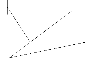
AutoCAD offers the Midpoint Between Two Points osnap, which enables you to select a point midway between two other points without drawing a temporary line. The AutoCAD Cal command offers another way to accomplish this. In the following example, you’ll use QuickCalc to perform the same function as an example of how you can acquire point data and manipulate it to derive other coordinate locations:
Figure 15-29 The endpoints of the two lines
In step 2, you used the end function that is built into QuickCalc. As you saw, the end function lets you select the endpoint of an object (as you did in step 3). The end + end in the formula tells QuickCalc to add the two coordinates you selected in step 3. The /2 in the formula divides the sum of the coordinates to find their average, which happens to be the midpoint between the two points.
If you were to perform this calculation using pencil and paper, you would add the x-, y-, and z-coordinate values of each point separately and then divide each coordinate by 2. Finally, you would combine the resulting x-, y-, and z-coordinates back into a single point location.
Using Osnap Modes in QuickCalc Expressions
In the previous exercise, you used osnap modes as part of arithmetic formulas (or expressions, as they’re called in AutoCAD). QuickCalc treats osnap modes as temporary placeholders for point coordinates until you pick the points.
The expression
(end + end)/2finds the average of two values. In this case, the values are coordinates, so the average is the midpoint between the two coordinates. You can take this one step further and find the centroid of a triangle by using this expression:
(end + end + end)/3Note that you enter only the first three letters of the osnap mode in calculator expressions. Table 15-3 shows what to enter in an expression for osnap modes. The table includes two items that aren’t really osnap modes, although they work similarly when they’re used in an expression. The first is Rad. When you include Rad in an expression, you get the following prompt:
Select circle, arc or polyline segment for RAD function:You can then select an arc, a polyline arc segment, or a circle to obtain a radius for the expression.
Table 15-3: The geometry calculator’s osnap modes
| Calculator osnap | Meaning |
| End | Endpoint |
| Ins | Insert |
| Int | Intersection |
| Mid | Midpoint |
| Cen | Center |
| Nea | Nearest |
| Nod | Node |
| Qua | Quadrant |
| Per | Perpendicular |
| Tan | Tangent |
| Rad | Radius of object |
| Cur | Cursor pick |
The other item, Cur, prompts you for a point. Instead of looking for specific geometry on an object, it just locates a point. You could have used Cur in the previous exercise in place of the End and Cen modes to create a more general-purpose midpoint locator, as in the following formula:
(cur + cur)/2Pasting to the Command Line
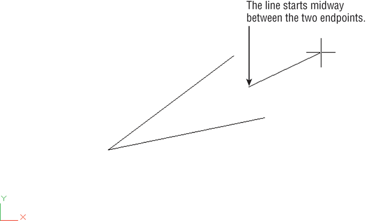
Now that you have the coordinate for the midpoint, try the next exercise to apply that coordinate to a command. In this example, you’ll use the coordinate found in step 3 as the starting point for a line:
Figure 15-30 Select Paste To Command Line.
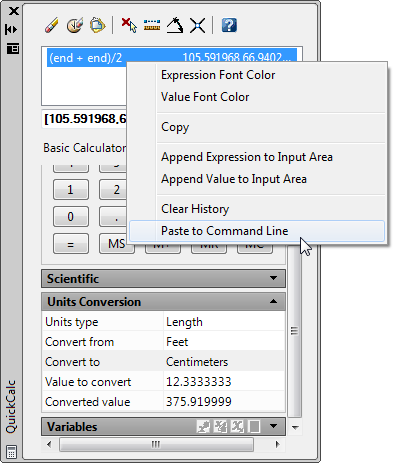
Figure 15-31 Starting a line between two endpoints
Finding Fractional Distances Between Two Points
Another ability AutoCAD users commonly need is to find a location that is a fractional distance along a line. For example, users frequently need to find a point that is one-third the distance from the endpoint of a line. Here’s how that can be accomplished using QuickCalc:
Figure 15-32 Select these points to find a point that is one-third the distance from an endpoint.
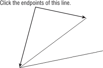
Figure 15-33 A line starting at a point that is one-third the distance from the endpoint
In step 1, you used a formula that contained the plt function. This function finds a point that is a particular percentage between two points. You specify the two points first, using the now-familiar end function, and then you specify the percentage between the two endpoints as a decimal value. The (end, end, 0.333) indicates the two endpoints you selected in step 2 and the percentage as a decimal value of 0.333.
In the formulas you’ve seen so far, you’ve used the end function to select endpoints. If you prefer to select your own osnaps during the point-selection process, you can use the cur function. Cur lets you use any osnap you want when selecting points. In the first example, you could use (cur + cur)/2 instead of (end + end)/2.
The plt function is just one of several special functions you can use with QuickCalc. Table 15-4 lists other functions you can use to find points in your drawing and gather other data. In the table, 2D points are represented as pt1, pt2, and so on. Three-dimensional points, or points describing a plane, are indicated by ptp1, ptp3, and so on. The center of an arc or a circle is indicated with apex for a 2D location and apex1 and apex2 for a 3D axis.
Table 15-4: Functions in QuickCalc and the formats for their use
| Function and format | Description |
| Getvar(system variable name) | Gets the value of a system variable |
| Vec(pt1,pt2) | Returns the vector described by the distance between the two points |
| Vec1(pt1,pt2) | Returns the vector described by 1 unit length |
| Abs(vector) | Returns the absolute value of the length of a vector |
| Cur(no arguments required) | Gets a point |
| @(no arguments required) | Returns the last point |
| w2u(point) and u2w(point) | Converts world coordinates to current user coordinates (w2u) or user coordinates to world |
| Pld(pt1,pt2,distance) | Returns the point on a line at a specified distance |
| Plt(pt1,pt2,percent) | Returns the point on a line at a percentage (decimal) of the line length |
| Rot(pt1,apex,angle) or Rot(pt1,apex1,apex2,angle) | Returns the rotation angle of a point (pt1) about an apex |
| Ill(pt1,pt2,pt3,pt4) | Returns the intersection between two lines |
| Ilp(pt1,pt2,ptp1,ptp2,ptp3) | Returns the intersection between a line and a plane; five points required |
| Dist(pt1,pt2) | Returns the distance between two points |
| Dpl(point,pt1,pt2) | Returns the shortest distance between a point and a line |
| Dpp(point,ptp1,ptp2,ptp3) | Returns the shortest distance between a point and a plane |
| Rad (no arguments required) | Returns a radius |
| Ang(vector or pt1,pt2 or apex,pt1,pt2 or apex1,pt1,pt2,apex2) | Returns an angle; can use up to four parameters when working in 3D |
| Nor(vector or pt1,pt2or ptp1,ptp2,ptp3) | Finds the normal of a vector or plane |
Using QuickCalc While in the Middle of a Command
In all the previous examples, you’ve used QuickCalc as a stand-alone calculator. You’ve also seen how you can insert a calculation into the command line while a command is in progress. A third way to work with QuickCalc is to open it while in the middle of a command.
In a previous exercise, you used the (end + end)/2 formula to find the midpoint between two points, and then you inserted the resulting value into the Line command. Suppose you start the Line command before you open QuickCalc. Try the following to see how you can use QuickCalc once a command has been initiated:
In this exercise, you saw that an Apply option appears at the bottom of the QuickCalc window along with Close and Help buttons. These buttons aren’t present when you open QuickCalc with no command active. The Apply button executes the formula and then immediately returns the resulting value to the command. Using QuickCalc in this way eliminates a few steps.
Finding a Point Relative to Another Point
Now, suppose you want to start a line at a relative distance from another line. The following steps describe how to use the calculator to start a line from a point that is 2.5″ in the x-axis and 5.0″ in the y-axis from the endpoint of another line:
In this example, you used the Endpoint osnap mode to indicate a point of reference. This is added to Cartesian coordinates in square brackets, describing the distance and direction from the reference point. You could enter any coordinate value within the square brackets. You also could enter a polar coordinate in place of the Cartesian coordinate, as in the following: end + [5.59<63].
You can replace the end in the expression with the at sign (@) to continue from the last point you selected. Also, it’s not necessary to include every coordinate in the square brackets. For example, to indicate a displacement in only one axis, you can leave out a value for the other two coordinates while leaving in the commas, as in the following examples:
[4,5] = [4,5,0]
[,1] = [0,1,0]
[,,2] = [0,0,2]
Combining Coordinates and Expressions
In the previous two examples, you saw that you can use an expression or enter coordinates. But what if you want to combine an expression within a coordinate? For example, in the beginning of this section, you added feet and inches and then transferred the result to the command line. In that example, you had to switch back and forth between QuickCalc and the command line to create the response for the Command prompt. If you prefer, you can create an expression that supplies the entire command input. Here are the steps to do this:
End + [(4′+36+5′6)<45]In this exercise, you used the expression (4′+36+5′6) right in the middle of a coordinate value. As described earlier, the coordinate is within square brackets. By using this method, you can calculate measurements and apply them to commands more easily. The trick is to become familiar with the syntax QuickCalc requires so you can write these expressions without errors.
Storing Expressions and Values
The ability to create expressions to manipulate coordinates can be useful, but you may find it difficult to remember an expression once you’ve created it. Fortunately, QuickCalc offers the Variables section, which allows you to store frequently used expressions and values.
At the bottom of the QuickCalc window is the Variables section, which has its set of tools in its title bar (see Figure 15-34).
Figure 15-34 The Variables group
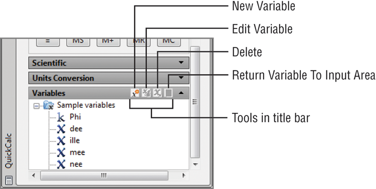
These tools let you add items to the list, edit items, or delete items from the list. A fourth option lets you send a variable to the main calculator input box. You can also right-click in the Variables section list box and select the same options from a context menu. In addition, the context menu lets you create a new category and rename an existing one.
The Variables section also contains a list of currently stored variables. Some sample variables are shown in the list. If you select a variable, you see a description of that variable’s function at the bottom of the group. You may need to click the bottom edge of the QuickCalc window and drag downward to see the description.
To use an existing variable, select it from the list and click the Return Variable To Input Area button; it looks like a calculator. To add a variable to the list, click the New Variable button, which opens the Variable Definition dialog box (see Figure 15-35).
Figure 15-35 The Variable Definition dialog box
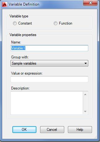
This dialog box lets you enter the properties of the variable and choose the type. In the Variable Properties group, you enter the name of the variable in the Name text box. In the Group With drop-down list, you select a category under which your formula will appear in the Variables list. You can also create a new category. The Value Or Expression box is where you put your formula; it can also be a single value, such as a number or a coordinate. At the bottom is a space to enter a description for the variable. This description will appear in the Variables group’s detail box at the bottom of QuickCalc.
At the top, in the Variable Type group, you see two options: Constant and Function. If you choose Function, your variable will behave as it normally does when you enter it in the input box. If you choose Constant and your variable is a formula, your variable will be executed when you close the Variable Definition dialog box. The resulting value will become the value for the variable.
To edit an existing variable, highlight it in the Variables group list, and then click the Edit Variable button to open the Variable Definition dialog box.
Guidelines for Working with QuickCalc
You may notice some patterns in the way expressions are formatted for the calculator. Here are some guidelines to remember:
- Coordinates are enclosed in square brackets.
- Nested or grouped expressions are enclosed in parentheses.
- Operators are placed between values, as in simple math equations.
- Object snaps can be used in place of coordinate values.
Table 15-5 lists all the operators and functions available in QuickCalc. You may want to experiment with these functions on your own. You can enter many of these operators using the keys on the number pad or in the scientific group.
Table 15-5: The QuickCalc functions
| Operator/function | What it does | Example |
| + or – | Adds or subtracts numbers or vectors | 2 – 1 = 1[a,b,c] + [x,y,z] = [a+x, b+y, c+z] |
| * or / | Multiplies or divides numbers or vectors | 2 * 4.2 = 8.4a*[x,y,z] = [a*x, a*y, a*z] |
| ^ | Returns the exponent of a number | 3^2 = 9 |
| Sin | Returns the sine of an angle | sin (45) = 0.707107 |
| Cos | Returns the cosine of an angle | cos (30) = 0.866025 |
| Tang | Returns the tangent of an angle | tang (30) = 0.57735 |
| Asin | Returns the arcsine of a real number | asin (0.707107) = 45.0 |
| Acos | Returns the arccosine of a real number | acos (0.866025) = 30.0 |
| Atan | Returns the arctangent of a real number | atan (0.57735) = 30.0 |
| Ln | Returns the natural log | ln (2) = 0.693147 |
| Log | Returns the base-10 log | log (2) = 0.30103 |
| Exp | Returns the natural exponent | exp (2) = 7.38906 |
| exp10 | Returns the base-10 exponent | exp10 (2) = 100 |
| Sqr | Squares a number | sqr (9) = 81.0 |
| Abs | Returns the absolute value | abs (–3.4) = 3.4 |
| Rnd | Rounds to the nearest integer | round (3.6) = 4 |
| trunk | Drops the decimal portion of a real number | trunc (3.6) = 3 |
| r2d | Converts radians to degrees | r2d (1.5708) = 90.0002 |
| d2r | Converts degrees to radians | d2r (90) = 1.5708 |
| Pi | Provides the constant pi | 3.14159 |
QuickCalc is capable of much more than the typical uses you’ve seen here. A description of its full capabilities extends beyond the scope of this text. However, the processes described in these sections will be helpful as you use AutoCAD. If you want to know more about QuickCalc, consult the AutoCAD Help User Documentation (enter QuickCalc in the InfoCenter input box).