
Part 5
Customization and Integration
- Chapter 26: Customizing Toolbars, Menus, Linetypes, and Hatch Patterns
- Chapter 27: Managing and Sharing Your Drawings
- Chapter 28: Keeping a Project Organized with Sheet Sets
Chapter 26
Customizing Toolbars, Menus, Linetypes, and Hatch Patterns
AutoCAD® 2014 software offers a high degree of flexibility and customization, enabling you to tailor the software’s look and feel to your requirements. In this chapter, you’ll see how to customize AutoCAD so that it integrates more smoothly into your workgroup and office environment.
The first part of the chapter shows how to adapt AutoCAD to fit your particular needs. You’ll learn how to customize AutoCAD by modifying its menus, and you’ll learn how to create custom macros for commands that your workgroup uses frequently.
In this chapter, you will learn to:
- Use workspaces
- Customize the user interface
- Create macros in tools and menus
- Edit keyboard shortcuts
- Save, load, and unload your customizations
- Understand the Diesel macro language
- Create custom linetypes
- Create hatch patterns
Using Workspaces
Once you’re comfortable with AutoCAD, you may find that you like a certain arrangement of Ribbon panels, toolbars, and palettes or that you have several sets of panels and toolbars that you like to use, depending on your type of work. You’ve already worked with two of the workspaces AutoCAD offers out of the box: Drafting & Annotation and 3D Modeling. You can also set up your own custom panel and toolbar arrangements and then save those arrangements for later retrieval using the Workspace feature. Let’s take a closer look at how you can create a custom workspace.
The Workspace Switching tool and its menu are shown in Figure 26-1. In the “Getting to Know the 3D Modeling Workspace” section in Chapter 21, “Creating 3D Drawings,” you saw how you can use a similar tool, the Workspace drop-down list, to switch to a 3D modeling workspace. You can save multiple arrangements of panels, toolbars, and palettes and then recall them easily by selecting them from the Workspace Switching tool in the status bar or Workspace drop-down list in the Quick Access toolbar.
Figure 26-1 The Workspace Switching tool
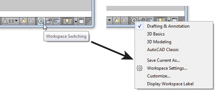
Click the Workspace Switching tool on the status bar and select Workspace Settings to open the Workspace Settings dialog box, shown in Figure 26-2. You can also select Workspace Settings from the Workspace drop-down list in the Quick Access toolbar or type Wssettings↵.
Figure 26-2 The Workspace Settings dialog box
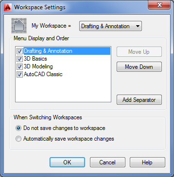
With the Workspace Settings dialog box open, you can see the Drafting & Annotation, 3D Basics, 3D Modeling, and AutoCAD Classic options. If you’ve used the Initial Setup Wizard to create an industry-specific workspace, you’ll see the Initial Setup Workspace option here as well. From here, you can control the behavior of the settings.
The check box next to each setting lets you control whether the item appears in the Workspace Switching tool menu. For example, if you remove the check mark from the AutoCAD Classic setting, you’ll see only Drafting & Annotation, 3D Basics, and 3D Modeling in the Workspace Switching tool menu.
The My Workspace drop-down list lets you select which workspace setting is activated when you click the My Workspace tool on the Workspace toolbar. (You’ll see the Workspace toolbar when you switch to the AutoCAD Classic workspace.) You can use this option for your most frequently used workspace settings.
The options in the When Switching Workspaces group at the bottom of the Workspace Settings dialog box let you determine whether workspace changes are saved automatically. For example, if you select Automatically Save Workspace Changes, then the next time you switch to a different workspace setting, AutoCAD will save any changes you’ve made to the current workspace.
The Workspace Switching tool is the easiest customization feature you’ll find in AutoCAD, and it can go a long way toward helping you stay organized. But workspaces are just the tip of the iceberg when it comes to customizing AutoCAD. Next, you’ll delve into the Customize User Interface (CUI) feature to see how you can customize the AutoCAD menus, panels, and toolbars directly.
Customizing the User Interface
Out of the box, AutoCAD offers a generic arrangement of Ribbon panels, tools, and palettes that works fine for most applications. But the more you use AutoCAD, the more you may find that you tend to use tools that are scattered over several Ribbon panels. You’ll probably feel that your work would go more easily if you could create a custom set of panels and menus to consolidate those tools. If you’re at the point of creating custom macros, you may want a way to have easy access to them.
The Customize User Interface (CUI) dialog box is a one-stop location that gives you nearly total control over the menus, panels, and toolbars in AutoCAD. With the CUI feature, you can mold the AutoCAD interface to your liking. The main entry point to the CUI is the Customize User Interface dialog box.
The following section introduces you to the CUI by showing you how to add a tool to the Draw Ribbon panel. You’ll also get a chance to see how to create an entirely new panel and custom tools.
Taking a Quick Customization Tour
The most direct way to adapt AutoCAD to your way of working is to customize the Ribbon. AutoCAD offers new users an easy route to customization through the Customize User Interface dialog box. With this dialog box, you can create new Ribbon panels and toolbars, customize tools, and even create new icons. You can also create keyboard shortcuts.
To get your feet wet, try adding a tool to the Draw panel:
Figure 26-3 The Customize User Interface dialog box
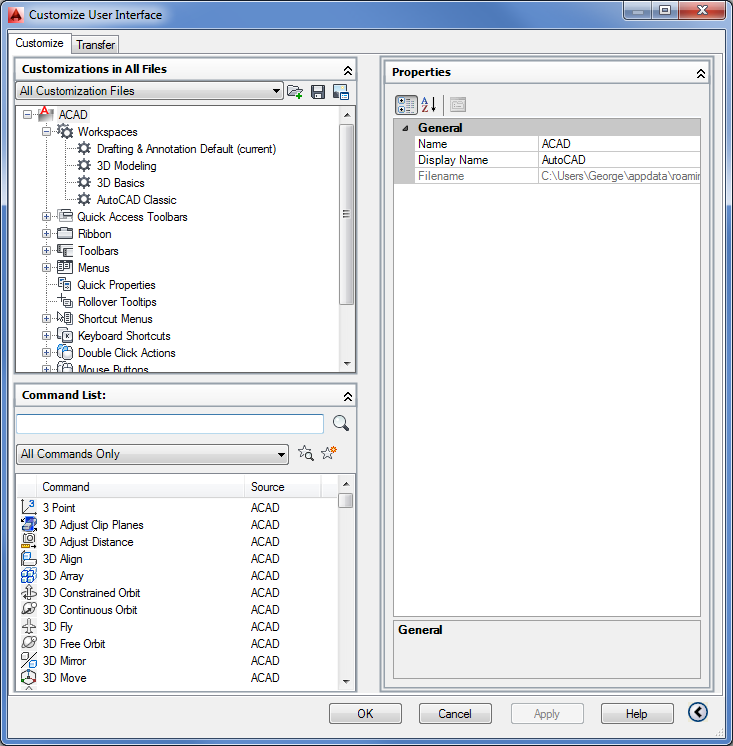
Figure 26-4 The Draw Ribbon panel appears.
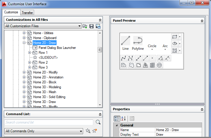
Figure 26-5 Choose the Dimension category.
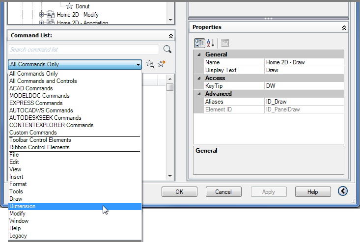
Figure 26-6 The Panel Preview area changes when you select an element from the Command List group or the Customizations In All Files group.
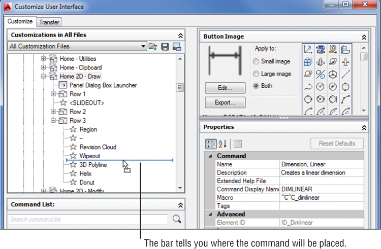
Figure 26-7 After positioning the Dimension icon
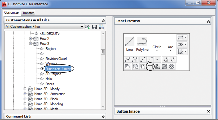
Figure 26-8 The tool is in place.
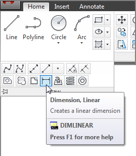
You’ve just added a command to the Draw panel. You can follow the previous steps to add any command to any Ribbon panel, toolbar, or menu bar menu. Now suppose you change your mind and you decide to remove Dimension, Linear from the Draw panel. Here’s how it’s done:
Dimension, Linear has been removed from the Draw panel. As you’ve just seen, adding tools to a panel is a matter of clicking and dragging the appropriate item from one list to another. To remove tools, right-click the tool and select Remove.
Before you go too much further, you may want to know a little more about the Customize User Interface dialog box and how it works. You saw briefly how each group displayed different elements of the AutoCAD interface, from a listing of panel tools to an individual tool’s icon. Let’s look at each group independently to see how it’s organized.
Understanding the Customizations In All Files Panel
In the previous exercise, where you placed the Dimension, Linear command in the Draw panel, you saw an arrowhead appear when you hovered over an option. The arrowhead indicates the location where the command will be placed when you release the mouse button. If the arrowhead points to a command, the new command will be placed after the item indicated by the arrowhead. If the item is a folder icon, then the new command will be placed inside that folder.
You may see items called Sub-Panel options. These allow you to mix single tools and rows like the Line tool and the three rows you see to the right of the Line tool at the top of the Draw panel. Finally, the <SLIDEOUT> item you see in the list indicates the division between the main part of the panel and the expanded panel. Figure 26-9 shows how the list in the Customizations In All Files group relates to the Ribbon panel components.
Figure 26-9 The Customizations In All Files list compared to the Ribbon panel preview
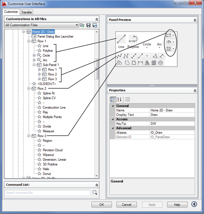
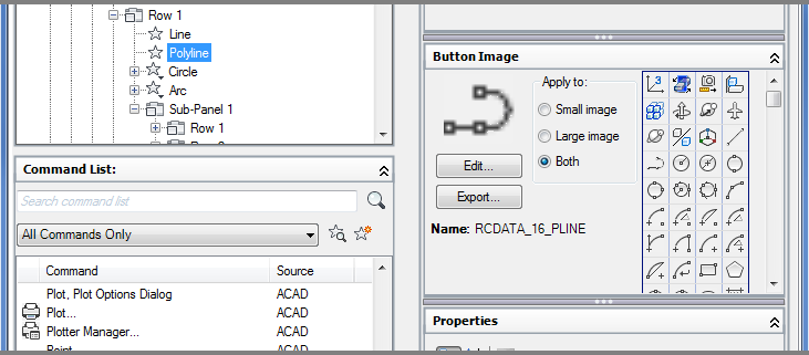
Notice that the Line, Polyline, Circle, and Arc tools straddle the two rows in the expanded Draw panel and are at the same level as the Sub-Panel 1 options of Rectangle, Ellipse, and Hatch. This is done by placing the Line, Polyline, Circle, and Arc commands at the same level as the Sub-Panel 1 option. The Sub-Panel 1 option is further divided into rows. Figure 26-10 shows how the rows appear when they are expanded. Flyouts on the Ribbon panel appear as Drop-Down options in the Customizations In All Files group.
If you expand a Drop-Down option, you’ll see the tools that appear in the flyouts of the tool in the panel (see Figure 26-11).
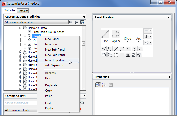
You can add new panels, rows, sub-panels, and drop-downs (flyouts) by right-clicking an item in the list and selecting the appropriate option from the context menu (see Figure 26-12). These types of interface elements are called containers in the Customize User Interface dialog box.
Figure 26-10 The Sub-Panel 1 option contains the rows that in turn contain flyouts labeled as “Drop-Down” options.
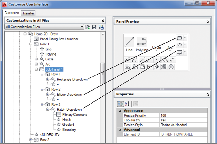
Figure 26-11 The tools in the Customizations In All Files panel’s Drop-Down list appear in the appropriate flyout.
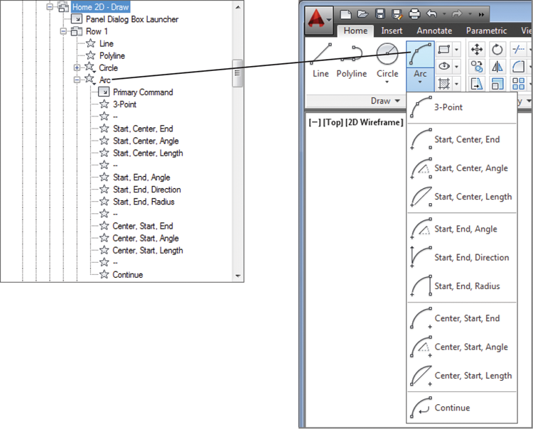
Figure 26-12 Create new containers via the context menu.
If you understand the structure of these lists, you’ll find that it is quite easy to customize the Ribbon panels to your liking.
Getting the Overall View
When you first opened the Customize User Interface dialog box by right-clicking the Ribbon, you saw a listing of the AutoCAD interface elements in the Customizations In All Files group. Just as you saw with the Ribbon panels, each of the other interface elements in the list can be expanded to get to its individual commands. If you expand the Toolbars list, for example, all the AutoCAD toolbars are available. Expand a toolbar and the commands contained in the toolbar are displayed. As you saw earlier, you can expand the Ribbon Panels list to gain access to the Ribbon panels. Table 26-1 lists all the interface elements in the Customizations In All Files group with a brief explanation of their contents.
Table 26-1: Main headings in the Customizations In All Files group
| Item | What it contains |
| Workspaces | Workspaces that are currently available |
| Quick Access Toolbars | Quick Access toolbars |
| Ribbon | The Ribbon tabs, panels, and contextual tab states |
| Toolbars | Toolbars |
| Menus | Menu bar menus |
| Quick Properties | Options on the Quick Properties palette |
| Rollover Tooltips | Rollover tooltip settings |
| Shortcut Menus | Menus shown with right-clicks |
| Keyboard Shortcuts | Current keyboard shortcuts, such as Ctrl+C and Ctrl+V |
| Double-Click Actions | Object-dependent double-click actions |
| Mouse Buttons | Mouse button options, such as Shift+click and Ctrl+click |
| LISP Files | Any custom LISP files that are used with your CUI |
| Legacy | Any legacy custom items you use, such as table or screen menus |
| Partial Customization Files | Custom CUI files that have been included in the main CUI file |
You can customize any of the interface elements. For example, if you want to create new keyboard shortcuts, you can expand the Keyboard Shortcuts listing and add new shortcuts or edit existing ones. Right-click any item to add or delete options. If you click an item, its properties appear in the Properties group, where you can modify the item’s function. Just as you added the Dimension, Linear command to the Draw panel, you can click and drag a command into one of the menus under the Menus listing to add a command there.
You also see some options in the Customizations In All Files title bar. These options give you control over what is displayed in this group. You can also load and save CUI files from here.
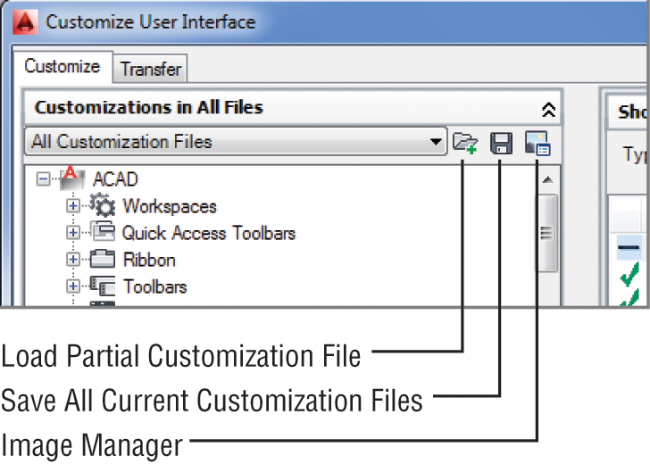
You’ll learn more about these options later in this chapter.
Finding Commands in the Command List
You’ve already seen how the Command List group contains all the commands in AutoCAD. You also saw that you can click and drag these items into options in the Customizations In All Files group. This list also contains predefined macros, icons used for tools, and control elements (called combo boxes in the Ribbon panels), which are the drop-down lists you see in panels and toolbars. The layer drop-down list in the Layers panel is an example of a control element. The drop-down lists in the Home tab’s Properties panel are also examples of control elements. When you select an item in the Command List group, you see its properties in the Properties group or its icon in the Button Image group, or both. The control elements are the exception to this because they have no editable features.
Opening Preview, Button Image, and Shortcuts
You’ve already seen how you can get a preview of a Ribbon panel by selecting the panel from the Customizations In All Files group. If you click a Ribbon panel from the list, you’ll see the Panel Preview group, which shows you how the selected panel will appear. Previews aren’t editable and are there for your reference.
If you click a tool listing—or element in AutoCAD nomenclature—in the Customizations In All Files group, you see the Button Image group. You can open this group by clicking the double arrowhead to the right of the Button Image group title bar. You may also need to adjust the bottom border of the Button Image group downward so you can see more of the group. This group lets you select an icon for that tool by clicking a list of icons (see Figure 26-13), or you can edit an existing icon or create an entirely new icon. You’ll get a chance to see this firsthand later in this chapter.
Figure 26-13 The Button Image group
The Keyboard Shortcuts area in the Customizations In All Files group shows the Shortcuts group, which lists the existing keyboard shortcuts.
Getting to the Core of Customization in the Properties Group
Finally, when you’re ready to do some serious customizing, you’ll work with the Properties group. You see the Properties group in the lower half of the right side of the Customize User Interface dialog box when you select a command from the left side of the dialog box.
The Properties group is set up just like the Properties palette, and it works the same way. On the left side, you see a listing of options. To the right of each option is a description or a text input box where you can make changes (see Figure 26-14).
If you go to the Customizations In All Files group and select the Line tool under the Home 2D – Draw option that you worked on earlier (Ribbon ⇒ Panels ⇒ Home 2D – Draw ⇒ Row 1 ⇒ Line), you see the properties for that tool in the Properties group, as shown in Figure 26-14. You’ll have to close the Button Image group to get a complete view of the Properties group. You can close any group by clicking the double arrow on the right side of the group’s title bar.
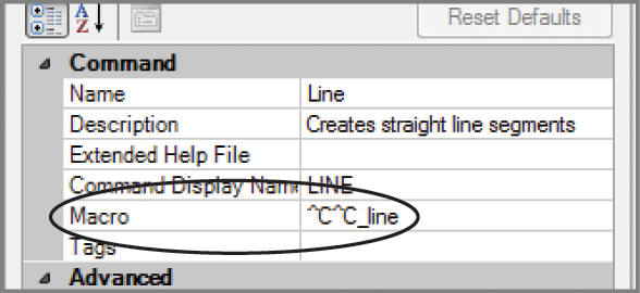
In the Command category, you see the Line tool’s name in the Command Name listing. You also see the description that is displayed in the tool tip for the Line tool. You can change this description here in the Properties group, and the description will change in the status bar.
Figure 26-14 The Properties group showing the properties for the Line tool
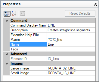
In the Macro listing, you see the command as it would be entered through the keyboard. The ^C^C that precedes the actual line command input is equivalent to pressing the Esc key twice. If you scroll down, you’ll see the Advanced category, which offers information regarding the ID of this particular tool. Finally, the Images category lists the name of the image files used for the Line tool icon. Two icons are listed: one for the large icon version and one for the small icon version of the tool.
You’ll get a chance to work with the Properties group later in this chapter. Next you’ll try your hand at creating your own custom toolbar.
Creating Your Own Ribbon Panels and Menus
Earlier, we mentioned that you can collect your most frequently used tools into a custom Ribbon panel or toolbar. Now that you’ve had a chance to become familiar with the Customize User Interface dialog box, you can try the following exercise to create your own Ribbon panel:
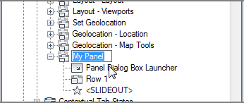
Figure 26-15 The new Panel1 name changed to My Panel
You now have a custom Ribbon panel. You’ll want to start to populate your panel with some commands. You’ve already seen how this works, but to review try adding a few commands:
Figure 26-16 Point to the Row 1 option, and you’ll see the arrowhead appear.
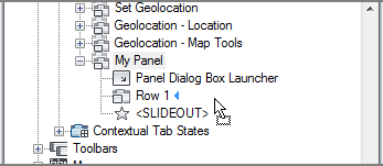
You can add several more rows to your panel, but after the first row, additional rows will be placed below <SLIDEOUT>, in the expanded portion of the panel.
Customizing Ribbon Panel Tools
Let’s move on to more serious customization. Suppose you want to create an entirely new button with its own functions. For example, you might want to create a set of buttons that insert your favorite symbols. Or you might want to create a Ribbon panel containing a set of tools that open some of the other toolbars that are normally put away.
Creating a Custom Tool
Follow these steps to create a custom tool:
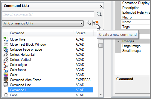
Figure 26-17 Click the Create A New Command tool and a new command appears in the list.
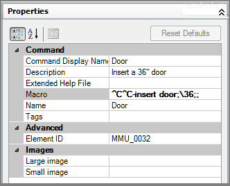
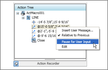
^C^C-insert door;36;;The series of keystrokes you entered for the macro in step 5 are the same as those you would use to insert the door with the addition of a few special characters. The semicolons are equivalent to a ↵, and the backward slash () is a special macro code that tells AutoCAD to pause the macro for user input. In this case, the pause allows you to select the insertion point for the door. The Properties group should look like Figure 26-18.
Figure 26-18 The Properties group for your new custom tool that inserts a door block
You’ve created your panel, but it will not appear anywhere in the AutoCAD interface until you add it to a Ribbon tab group. Here’s how this is done:
Next try the custom tool to make sure it works:
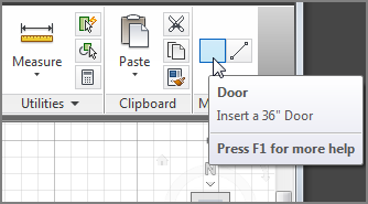
In this example, you created a custom tool that inserts the door block. Later in this chapter, you’ll learn more about creating macros for menus and tools. Next you’ll learn how to add a custom icon for your custom tool.
Creating a Custom Icon
You have all the essential parts of the button defined. Now you just need to create a custom icon to go with your Door button:
Figure 26-19 Draw this door icon.
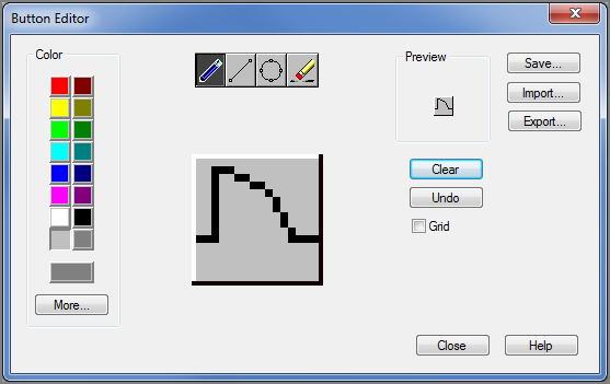
The Button Editor behaves like a simplified image editing tool, and it is fairly straightforward to use. The only part that may be confusing is that you have to clear the image and save any new image under a new name.
You can continue to add more buttons to build a panel of symbols. Of course, you’re not limited to a symbols library. You can also incorporate your favorite macros or even AutoLISP® routines that you accumulate as you work with AutoCAD. The possibilities are endless.
Creating Macros in Tools and Menus
Combining existing commands into new panels or toolbars can be useful, but you’ll get even more benefit from the CUI by creating your own macros. Macros are predefined sets of responses to commands that can help automate your most frequently used processes.
Early on, you saw how a macro was included in a tool to insert a door. You added a special set of instructions in the Macro option of the Properties group to perform the door insertion and scale. You also saw how the Line command was formatted as part of a tool.
Let’s take a closer look at how macros are built. Start by looking at the existing Line tool and how it’s formatted.
The Macro option for the Line tool starts with two ^C elements, which are equivalent to pressing the Esc key twice. This cancels any command that is currently operative. The Line command follows, written just as it would be entered through the keyboard. Two Cancels are issued in case you’re in a command that has two levels, such as the Edit Vertex option of the Pedit command.
The underscore character (_) that precedes the Line command tells AutoCAD that you’re using the English-language version of this command. This feature lets you program non-English versions of AutoCAD by using the English-language command names.
You may also notice that there is no space between the second ^C and the Line command. A space in the line would be the same as ↵. If there were a space between these two elements, ↵ would be entered between the last ^C and the Line command, causing the command sequence to misstep. Another way to indicate ↵ is by using the semicolon, as in the following example:
^C^C_Line;;In this sample menu option, the Line command is issued and then an additional ↵ is added. The effect of choosing this option is a line that continues from the last line entered into your drawing. The two semicolons following Line tell AutoCAD to start the Line command and then issue ↵ twice; the first ↵ starts the Line command, and then the second ↵ tells AutoCAD to begin a line from the endpoint of the last line entered. (AutoCAD automatically issues a single ↵ at the end of a menu line. In this case, however, you want two instances of ↵, so they must be represented as semicolons.)
Pausing for User Input
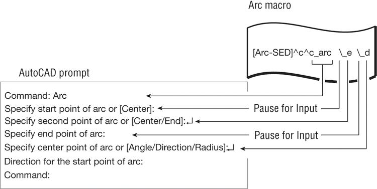
Another symbol used in the Macro option is the backslash (); it’s used when a pause is required for user input. For example, the following sample macro starts the Arc command and then pauses for your input:
^C^C_arc \_e \_dThe space between ^C^C_arc and the backslash () represents pressing the spacebar. The backslash indicates a pause to enable you to select the starting endpoint for the arc. The _e represents the selection of the Endpoint option under the Arc command after you’ve picked a point. A second backslash allows another point selection. Finally, the _d represents the selection of the Direction option. Figure 26-20 illustrates this. If you want the last character in a menu item to be a backslash, you must follow the backslash with a semicolon.
Figure 26-20 The execution of the Arc menu item
Opening an Expanded Text Box for the Macro Option
As you become more expert at creating macros, you may find the line provided in the Macro option too small for your needs. Fortunately, you can open an expanded text box in which to write longer macros. For example, suppose you want to include the following macro in a tool:
(defun c:breakat ()
(command "break" pause "f" pause "@")
)
breakat
This example shows the Breakat AutoLISP macro. Everything in this segment is entered just as it would be from the keyboard at the Command prompt. You may find it a bit cumbersome to try to enter this macro in the text box provided by the Macro option in the Properties group of the Customize User Interface dialog box, but if you click the Macro text box, a Browse button appears to the right (see Figure 26-21).
Figure 26-21 The Browse button in the Macro option
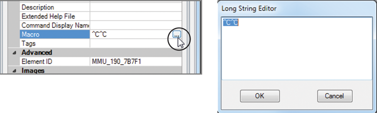
Click the Browse button to open the Long String Editor. You can then enter the macro and see it clearly. The following shows how it would be entered:
^C^C(defun c:breakat ()+
(command "break" pause "f" pause "@")+
);breakatIt starts with the usual ^C^C to clear any current commands. The plus sign at the end of lines 1 and 2 tells AutoCAD that the macro continues in the next line without actually breaking it. The break is there to help make the macro easier to read as you enter it. It’s okay to break an AutoLISP macro into smaller lines. Doing so can help you read and understand the program more easily.
Editing Keyboard Shortcuts
Another area of customization that can be useful is the keyboard shortcut. You probably already know about the standard Ctrl+C and Ctrl+V, which are shortcuts for the Windows Copy and Paste functions. In AutoCAD, Shift+Ctrl+A toggles groups on and off, and Ctrl+1 opens the Properties palette.
You can edit existing keyboard shortcuts or create new ones by opening the Keyboard Shortcuts list in the Customizations In All Files group of the Customize User Interface dialog box. If you expand this list, you see Shortcut Keys and Temporary Override Keys. These can be expanded to reveal their elements. Select an element to display its properties in the Properties group.
You can click and drag a command from the Command List group into the Shortcut Keys group and then edit its properties to set the shortcut keys you want to use for the command. For example, if you click and drag the 3D Free Orbit command from the Command List group into the Shortcut Keys list and then select it from that list, you see its properties in the Properties group (see Figure 26-22).
Figure 26-22 The Properties group
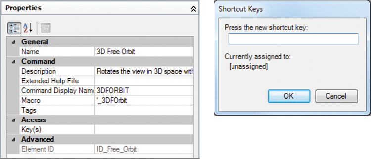
Click the Key(s) option in the Properties group, and then click the Browse button that appears to the far right of the Keys option to open the Shortcut Keys dialog box.
Click in the Press The New Shortcut Key input box, and then press the shortcut key you want to use for this command. For example, if you press Shift+Ctrl+Z, that sequence appears in the input box. If the shortcut you selected is already assigned to another command, you see a message that says so just below the input box. Click OK when you’re done.
Saving, Loading, and Unloading Your Customizations
You may want to save the custom menus, panels, and toolbars you create with the Customize User Interface dialog box so that you can carry them with you to other computers and load them for ready access. To save your customization work, you need to use the Transfer tab of the Customize User Interface dialog box. Here’s how it works:
Your customization is saved with the .cuix filename extension. Once it’s saved as a file, you can load it into another copy of AutoCAD by doing the following:
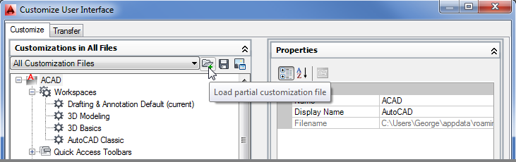
As an alternative to using the Customize User Interface dialog box, you can use the CUIload command. Enter Cuiload↵ at the Command prompt to open the Load/Unload Customizations dialog box.
Click the Browse button to locate and select your CUI file. Once you’ve done this, the name of your file appears in the File Name input box. You can then click the Load button to import it into your AutoCAD session.
Finally, if you want to unload a CUI file, do the following:
Understanding the Diesel Macro Language
Diesel is one of many macro languages AutoCAD supports, and you can use it to perform simple operations and add some automation to menus. As with AutoLISP, parentheses are used to enclose program code.
In the following sections, you’ll look at the different ways to use the Diesel macro language. You’ll start by using Diesel directly from the command line. This section will show you how a Diesel macro is formatted, and it will give you a chance to see Diesel in action. Then you’ll go on to see how Diesel can be used as part of a menu option to test the current state of AutoCAD. In the third section, you’ll see how Diesel can be used as part of the menu label to control what is shown in the menu. Finally, you’ll learn how to use Diesel with field objects to control text in your drawing.
Using Diesel at the Command Line
You can use Diesel at the AutoCAD command line by using a command called Modemacro. The Modemacro command sends information to the status bar. Diesel can be used with Modemacro to perform simple tasks.
Try the following exercise to experiment with Diesel:
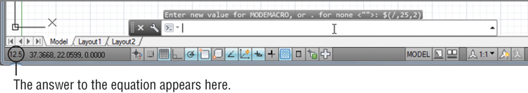
The equation you entered in step 2 is referred to as an expression. The structure of Diesel expressions is similar to that of AutoLISP expressions. The dollar sign tells AutoCAD that the information that follows is a Diesel expression.
A Diesel expression must include an operator of some sort, followed by the items to be operated on. An operatoris an instruction to take a specific action, such as adding two numbers or dividing one number by another. Examples of mathematical operators include the plus sign (+) for addition and the forward slash (/) for division.
The operator is often referred to as a function and the items to be operated on are referred to as the arguments to the function, or simply the arguments. In the expression (/,25,2), the / is the function and 25 and 2 are the arguments. All Diesel expressions, no matter what size, follow this structure and are enclosed by parentheses.
Parentheses are important elements of an expression. All parentheses must be balanced; for each left parenthesis, there must be a right parenthesis.
You can do other things with Diesel besides performing calculations. The getvar function is an AutoLISP function that you can use to obtain the drawing prefix and name. Try the following to see how Diesel uses getvar:
In this example, the getvar function extracts the drawing prefix and name and displays it in the status bar. You can use getvar to extract any system variable you want. If you’ve been working through the tutorials in this book, you’ve seen that virtually all AutoCAD settings are also controlled through system variables. (The Help section of the Autodesk Exchange window contains a list of all the system variables. See Chapter 2, “Creating Your First Drawing,” for more on Autodesk Exchange.) This can be a great tool when you’re creating custom menus because with getvar, you can poll AutoCAD to determine the state of a given system variable. For example, you can find out what command is currently being used. Try the following exercise to see how this works:
This information can be useful in building a menu when you want an option to perform a specific task depending on which command is currently active.
Using Diesel in a Custom Menu Macro
So far, you’ve been experimenting with Diesel through the Modemacro command. Using Diesel in a menu macro requires a slightly different format. You still use the same Diesel format of a dollar sign followed by the expression, but you don’t use the Modemacro command to access Diesel. Instead, you use $M=. You can think of $M= as an abbreviation for Modemacro.
Here’s a Diesel expression that you can use in a menu macro:
^C^C_Blipmode;$M=$(-,1,$(getvar,Blipmode))This menu option turns Blipmode on or off depending on Blipmode’s current state. Blipmode is a feature that displays point selections in the drawing area as tiny crosses. These tiny crosses, or blips, don’t print and can be cleared from the screen with a redraw. They can be helpful when you need to track your point selections.
In this example, the Blipmode command is invoked, and then the $M= tells AutoCAD that a Diesel expression follows. The expression
$(-,1,$(getvar,Blipmode))returns either 1 or a 0, which is applied to the Blipmode command to turn it either on or off. This expression shows that you can nest expressions. The most deeply nested expression is evaluated first, so AutoCAD begins by evaluating
$(getvar,Blipmode)This returns either 1 or a 0, depending on whether Blipmode is on or off. Next, AutoCAD evaluates the next level in the expression
$(-,1,getvar_result)in which getvar_result is either 1 or a 0. If getvar_result is 1, the expression looks like
$(-,1,1)which returns 0. If getvar_result is 0, the expression looks like
$(-,1,0)which returns 1. In either case, the end result is that the Blipmode command is assigned a value that is the opposite of the current Blipmode setting.
Using Diesel as a Menu Bar Option Label
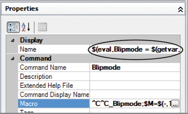
In the previous example, you saw how to use Diesel in a menu macro to read the status of a command and then return a numeric value to alter that status. You can also use Diesel as part of the menu bar option name so that the text it displays depends on certain conditions. The following expression shows how to write a menu option name to display the current setting for Blipmode. It includes Diesel code as the menu option label:
$(eval,Blipmode = $(getvar,blipmode))Normally, you would just have a menu name, but here you see some Diesel instructions. These instructions tell AutoCAD to display the message Blipmode = 1 or Blipmode = 0 in the menu, depending on the current Blipmode setting. You would place this code in the Properties group for the Blipmode custom command in the Customize User Interface dialog box. It goes in the Display/Name input box.
Here’s how it works. You see the familiar $(getvar,blipmode) expression, this time embedded in a different expression. You know that $(getvar,blipmode) returns either 1 or a 0, depending on whether Blipmode is on or off. The outer expression
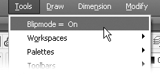
$(eval,Blipmode = getvar_result)displays Blipmode = and then combines this with getvar_result, which, as you’ve learned, will be either 1 or 0. The eval function evaluates any text that follows it and returns its contents. The end result is the appearance of Blipmode = 1 or Blipmode = 0 in the menu, depending on the status of Blipmode. Here’s how the properties look as a menu bar option under the Tools list of the Menus option in the Customizations In All Files panel:

You can get even fancier and set up the menu option label to read Blipmode On or Blipmode Off by using the if Diesel function. Here’s that same menu listing with additional Diesel code to accomplish this:
$(eval,Blipmode = $(if,$(getvar,blipmode),Off,On))In this example, the simple $(getvar,blipmode) expression is expanded to include the if function. The if function reads the result of $(getvar,blipmode) and then returns the Off or On value depending on whether $(getvar,blipmode) returns 0 or a 1. Here’s a simpler look at the expression:
$(if, getvar_result, Off, On)If getvar_result returns 1, the if function returns the first of the two options listed after getvar_result, which is Off. If getvar_result returns 0, the if function returns On. The second of the two options is optional. Here’s how the fancier Blipmode option appears in a menu:
You’ve just skimmed the surface of what Diesel can do. To get a more detailed description of how Diesel works, press the F1 function key to open the Autodesk Exchange website. Click the Contents tab, expand the Customization Guide listing, and click the DIESEL listing that appears.
Table 26-2 shows some of the commonly used Diesel functions. Check the AutoCAD Help dialog box for a more detailed list.
Table 26-2: Sample of Diesel functions
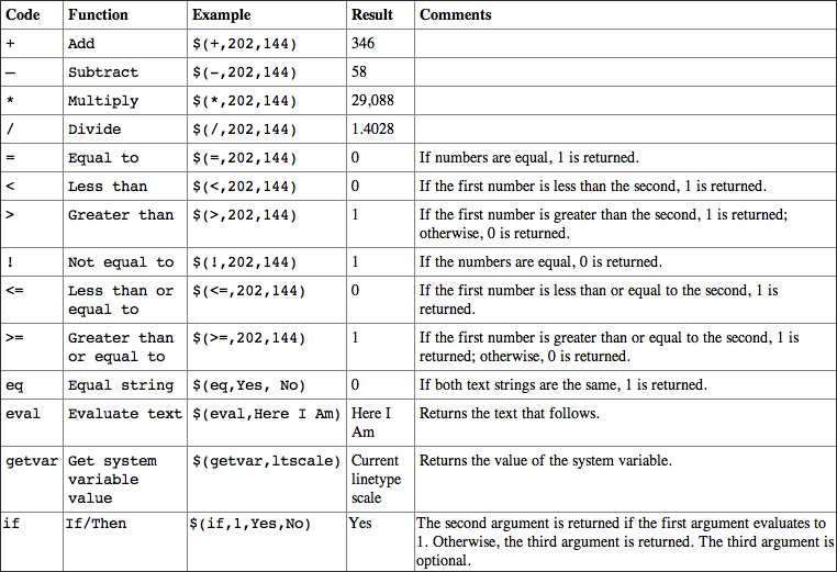
Note: To indicate true or false, Diesel uses 1 or 0.
Using Diesel and Fields to Generate Text
Using Diesel expressions in the status bar or in a menu can be helpful to gather information or to create a more interactive interface, but what if you want the results of a Diesel expression to become part of the drawing? You can employ field objects to do just that.
For example, suppose you want to create a note that shows the scale of a drawing based on the dimension scale. Further, you want the scale in the note to be updated automatically whenever the dimension scale changes. You can add a field object and associate it with a Diesel expression that displays the dimension scale as it relates to the drawing scale. Try the following steps to see how it’s done:
$(eval,Dimension Scale: 1/)$(/,$(getvar, dimscale),12)
$(eval, inch = 1 foot)Dimension Scale: 1/0.08333333 inch = 1 footThe resulting text may not make sense until you change the dimension scale to a value that represents a scale other than 1-to-1. Here’s how to do that:
Dimension Scale: 1⁄8 inch = 1 footIn this example, several Diesel operations were used. The beginning of the expression uses the eval operation to tell AutoCAD to display a string of text:
$(eval Dimension Scale: 1/)The next part tells AutoCAD to get the current value of the Dimscale system variable and divide it by 12:
$(/,$(getvar, dimscale),12)Notice that this is a nested expression: $(getvar,dimscale) obtains the value of the Dimscale system variable, which is then divided by 12. The end of the expression adds the final part to the text:
$(eval, inch = 1 foot)When it’s all put together, you get the text that shows the dimension scale as an architectural scale. Because it’s an AutoCAD text object, this text is part of the drawing.
Creating Custom Linetypes
As your drawing needs expand, the standard linetypes may not be adequate for your application. Fortunately, you can create your own. The following sections explain how to do so.
You’ll get an in-depth view of the process of creating linetypes. You’ll also learn how to create complex linetypes that can’t be created by using the Make Linetype Express tool.
Viewing Available Linetypes
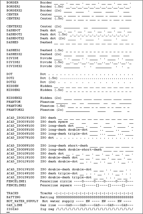
Although AutoCAD provides the linetypes most commonly used in drafting (see Figure 26-23), the dashes and dots may not be spaced the way you would like, or you may want an entirely new linetype.
Figure 26-23 The lines in this list of standard linetypes were generated with the underscore key (_), the period (.), and other symbols and are only rough representations of the actual lines.
To create a custom linetype, use the -Linetype command. Let’s see how this handy command works by first listing the available linetypes:
Creating a New Linetype
Next, let’s try creating a new linetype:
Custom – My own center line __________ _ ____________ ↵A,1.0,-.125,.25,-.125↵Remember, after you’ve created a linetype, you must load it in order to use it, as discussed in Chapter 5, “Keeping Track of Layers and Blocks.”
Understanding the Linetype Code
In step 7 of the previous exercise, you entered a series of numbers separated by commas. This is the linetype code, representing the lengths of the components that make up the linetype. The separate elements of the linetype code are as follows:
- The 1.0 following the A is the length of the first part of the line. (The A that begins the linetype definition is a code that is applied to all linetypes.)
- The first -.125 is the blank or broken part of the line. The minus sign tells AutoCAD that the line is not to be drawn for the specified length, which is 0.125 units in this example.
- Next comes the positive value 0.25. This tells AutoCAD to draw a line segment 0.25 units long after the blank part of the line.
- The last negative value, -.125, again tells AutoCAD to skip drawing the line for the distance of 0.125 units.
This series of numbers represents the one segment that is repeated to form the line (see Figure 26-24). You can also create a complex linetype that looks like a random broken line, as shown in Figure 26-25.
Figure 26-24 Linetype description with plotted line
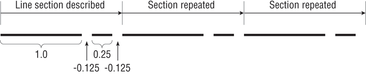
Figure 26-25 Random broken line
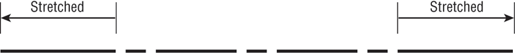
You may be wondering what purpose the A serves at the beginning of the linetype code. A linetype is composed of a series of line segments and points. The A, which is supplied by AutoCAD automatically, is a code that forces the linetype to start and end on a line segment rather than on a blank space in the series of lines. At times, AutoCAD stretches the last line segment to force this condition, as shown in Figure 26-26.
Figure 26-26 AutoCAD stretches the beginning and the end of the line as necessary.
As mentioned earlier, you can also create linetypes outside of AutoCAD by using a word processor or text editor such as Windows Notepad. The standard acad.lin file looks like Figure 26-23 with the addition of the code used by AutoCAD to determine the line segment lengths.
Normally, to use a linetype you’ve created you have to load it through either the Layer Properties Manager or the Linetype Manager dialog box (choose Other from the Linetype drop-down list in the Home tab’s Properties panel). If you use one of your own linetypes frequently, you may want to create a button macro so that it will be available as an option on a menu.
Creating Complex Linetypes
A complex linetype is one that incorporates text or special graphics. For example, if you want to show an underground gas line in a site plan, you normally show a line with the intermittent word GAS, as in Figure 26-27. Fences are often shown with an intermittent circle, square, or X.
Figure 26-27 Samples of complex linetypes
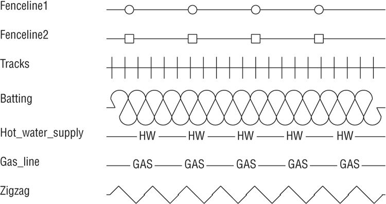
For the graphics needed to compose complex linetypes, use any of the symbols in the AutoCAD font files discussed in Chapter 10, “Adding Text to Drawings.” Create a text style by using these symbol fonts, and then specify the appropriate symbol by using its corresponding letter in the linetype description.
To create a linetype that includes text, use the same linetype code described earlier but add the necessary font file information in brackets. For example, say you want to create the linetype for the underground gas line mentioned previously by using just the letter G. You add the following to your acad.lin file:
*Gas_line, -G-G-G-
A,1.0,-0.25,["G",STANDARD,S=.2,R=0,X=-.1,Y=-.1],-0.25
The first line serves as a description for anyone looking at this linetype code. The next line is the code itself. Note that the code should not contain spaces.
The information in the square brackets describes the characteristics of the text. The actual text that you want to appear in the line is surrounded by quotation marks. Next are the text style, scale, rotation angle, X displacement, and Y displacement.
You can substitute A for the rotation angle (the R value), as in the following example:
A,1.0,-0.25,["G",standard,S=.2,A=0,X=-.1,Y=-.1],-0.25This has the effect of keeping the text at the same angle regardless of the line’s direction. Notice that in this sample, the X and Y values are -.1; this will center the Gs on the line. The scale value of .2 will cause the text to be 0.2 units high, so .1 is half the height.
In addition to fonts, you can specify shapes for linetype definitions. Instead of letters, shapes display symbols. Shapes are stored not as drawings but as definition files, similar to text font files. Shape files have the same .shx filename extension as font files and are also defined similarly. Figure 26-28 shows some symbols from sample shape files. The names of the files are shown at the top of each column.
Figure 26-28 Samples of shapes
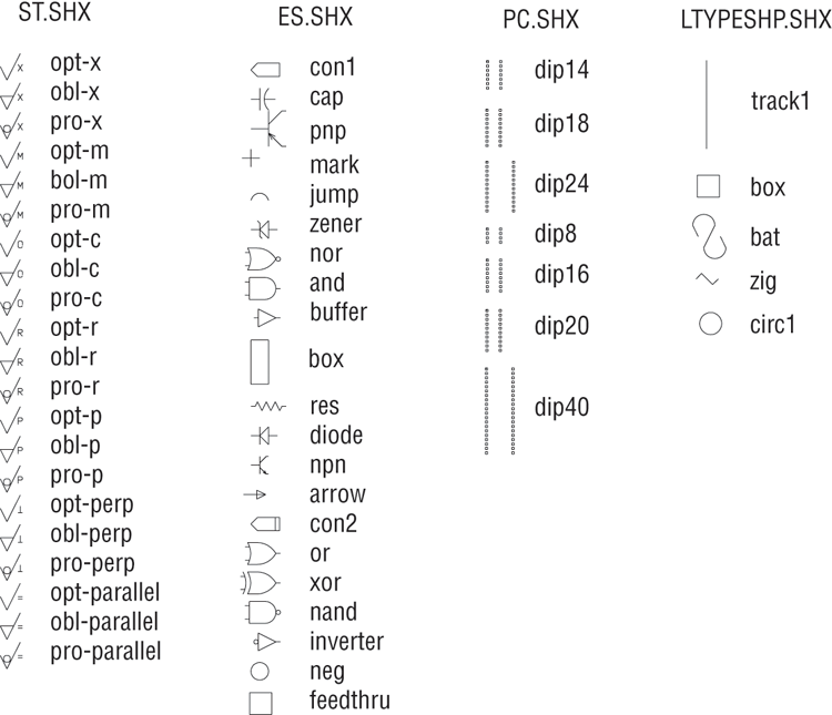
To use a shape in a linetype code, you use the same format as shown previously for text. However, instead of using a letter and style name, you use the shape name and the shape filename as in the following example:
*Capline, ====
a,1.0,-0.25,[CAP,ES.SHX,S=.5,R=0,X=-.1,Y=-.1],-0.25
This example uses the CAP symbol from the Es.shx shape file. The symbol is scaled to 0.5 units with 0 rotation and an X and Y displacement of –0.1.
Here is another example, this one using the arrow shape:
*Arrowline, -|-|-|-
a,1.0,-0.25,[ARROW,ES.SHX,S=.5,R=90,X=-.1,Y=-.1],-0.25
Just as with the Capline example, the ARROW symbol in this example is scaled to 0.5 units with 0 rotation and an X and Y displacement of –0.1. Figure 26-29 shows what the Arrowline linetype looks like when used with a spline.
Figure 26-29 The Arrowline linetype used with a spline
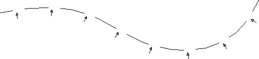
In this example, the Ltype generation option is turned on for the polyline. Note that the arrow from the Es.shx sample shape file is used for the arrow in this linetype.
Creating Hatch Patterns
AutoCAD provides several predefined hatch patterns from which you can choose, but you can also create your own. This section demonstrates the basic elements of pattern definition.
Unlike linetypes, hatch patterns can’t be created while you’re in an AutoCAD file. The pattern definitions are contained in an external file named acad.pat. You can open and edit this file with a text editor that can handle ASCII files, such as Notepad. Here is one hatch pattern definition from that file:
*SQUARE,Small aligned squares
0, 0,0, 0,.125, .125,-.125
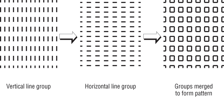
90, 0,0, 0,.125, .125,-.125You can see some similarities between pattern descriptions and linetype descriptions. They both start with a line of descriptive text and then give numeric values defining the pattern. However, the numbers in pattern descriptions have a different meaning. This example shows two lines of information. Each line represents a line in the pattern. The first line determines the horizontal line component of the pattern, and the second line represents the vertical component (see the image to the far right in Figure 26-30). A pattern is made up of line groups. A line group is like a linetype that is arrayed a specified distance to fill the area to be hatched. A line group is defined by a line of code, much as a linetype is defined. In the square pattern, for instance, two lines—one horizontal and one vertical—are used. Each of these lines is duplicated in a fashion that makes the lines appear as boxes when they’re combined. Figure 26-30 illustrates this point.
Figure 26-30 The individual and combined line groups
Look at the first line in the definition:
0, 0,0, 0,.125, .125,-.125This example shows a series of numbers separated by commas. It represents one line group. It contains four sets of information separated by blank spaces:
- The first component is the 0 at the beginning. This value indicates the angle of the line group, as determined by the line’s orientation. In this case, it’s 0 for a horizontal line that runs from left to right.
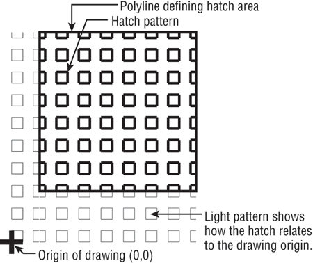
- The next component is the origin of the line group, 0,0. This doesn’t mean the line begins at the drawing origin (see Figure 26-31). It gives you a reference point to determine the location of other line groups involved in generating the pattern.
Figure 26-31 The origin of the patterns
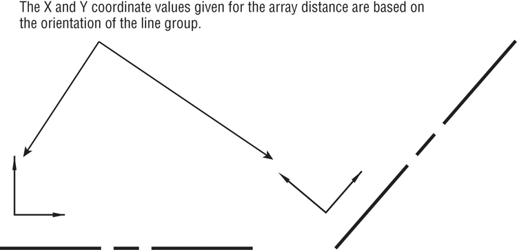
- The next component is 0,.125. This determines the distance and direction for arraying the line as illustrated in Figure 26-32. This value is like a relative coordinate indicating X and Y distances for a rectangular array. It isn’t based on the drawing coordinates, but on a coordinate system relative to the orientation of the line. For a line oriented at a 0° angle, the code 0,.125 indicates a precisely vertical direction. For a line oriented at a 45° angle, the code 0,.125 represents a 135° direction. Remember that the very first number in the line definition determines the angle of the line. In this example, the duplication occurs 90° in relation to the line group, because the X value is 0. Figure 26-33 illustrates this point.
Figure 26-32 The distance and direction of duplication
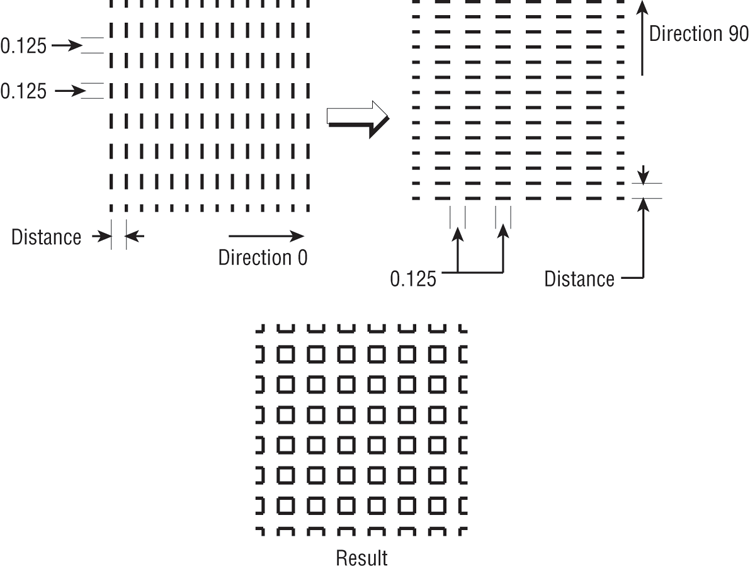
Figure 26-33 How the direction of the line group copy is determined
- The last component is the description of the line pattern. This value is equivalent to the value given when you create a linetype. Positive values are line segments, and negative values are blank segments. This part of the line group definition works exactly as in the linetype definitions you studied in the previous section.
This system of defining hatch patterns may seem somewhat limiting, but you can do a lot with it. Autodesk managed to come up with 69 patterns—and that was only scratching the surface.