
Chapter 28
Keeping a Project Organized with Sheet Sets
It’s rare to have a drawing project fit on one sheet. Most CAD projects require multiple sheets, sometimes numbering in the hundreds. With multiple sheets in a project, you often spend a fair amount of time checking cross-references between the drawings and making sure that information like sheet titles is correct.
Even the smallest project requires some coordination of cross-references between drawings in a set and checking for consistency across sheets. For example, a floor plan of a house will have callout symbols that direct you to a sheet with building elevations, construction details, or door and window schedules. As a CAD user, you eventually spend a lot of time just making sure that you have your set of drawings in the proper order and labeled correctly. Checking a set of drawings for continuity and correctness is a time-consuming job, and errors can easily creep in.
To help make your sheet coordination efforts easier, AutoCAD® 2014 software offers the Sheet Set Manager.
In this chapter, you will learn to:
- Understand sheet sets
- Create a sheet set from an existing project
- Manage title blocks and cross-references
- Customize sheet sets
- Archive, publish, and eTransmit sheet sets
Understanding Sheet Sets
The Sheet Set Manager is a tool that keeps track of all the drawings in a project. It also helps maintain the integrity of cross-references between sheets in a set of drawings by automatically updating sheet numbers throughout a set as sheets are added or moved. The Sheet Set Manager won’t replace a careful check of a set of drawings before they’re released for consumption, but it will reduce the amount of time you spend on coordinating and checking the drawings.
Sheet sets and the Sheet Set Manager can be a bit difficult to understand clearly, so in the following sections, take a moment to get a better idea of what sheet sets are all about.
Organizing by Reference Files and Sheet Files
To understand how sheet sets work better, you should consider the methods used to organize AutoCAD files. One common method for organizing files is to separate drawings into two categories: reference files and sheet files. You can think of reference files as the data sources. These are the drawing files that contain the core drawing geometry of a project. For example, they might be the floor plan drawings that contain the paving, finish, ceiling, and power information, all drawn in Model Space.
Sheet files are files that represent the actual printed sheets or pages in the drawing set. Sheet files include title block information as well as the different views of the reference files needed for the sheet. They also include view titles and scale information.
You use one layout view in the sheet file for each physical sheet that eventually gets printed. The reference files are included as Xrefs in the sheet files with the appropriate views and layers set up for each sheet.
For example, you might have one sheet file called A1 Floor Plan.dwg that has a title block in its layout view. That layout view has a viewport containing a view of an Xref floor plan file. Another sheet file called A2 Enlarged Plan.dwg might contain the same Xref, but with a layout view including multiple viewports to show a more detailed set of views of the plan.
The Sheet Set Manager can take this reference/sheet system of file organization and automate it. Without the Sheet Set Manager, you must create the sheet file, import the reference file, and then add a title block, viewport, and labels to produce a finished sheet. The Sheet Set Manager automates many of the fussy details of creating and maintaining the sheet files.
Managing Your Files with Sheet Sets
Sheet sets also serve as a way to gain an overview of your drawing set in a way similar to using the table of contents of a book. When you use the Sheet Set Manager, you can view a list of all the drawings in your project and quickly find and open the drawing on which you need to do work.
You can think of the Sheet Set Manager as a database that contains information about the drawings in the set. It uses a file with the .dst filename extension to store this information. Like a database, this file is updated automatically whenever you make changes to the sheet set. It doesn’t wait for you to save the sheet set data manually. In fact, you won’t see a Save option in the Sheet Set Manager.
The Sheet Set Manager can change multiple drawing files whenever a change affects the entire set. For example, if there is a change in the project information in the title block, you can update all the title blocks in the set by making a single change in the Sheet Set Manager. The Sheet Set Manager can keep track of title-block data such as submission dates, drawing titles, people who have worked on the individual drawings, and related information.
Finally, the Sheet Set Manager can help simplify the printing of whole sets of drawings by automatically setting up the AutoCAD Publish feature. It can help automate your archiving tasks and help collect all the necessary files to send your set to a different location for editing.
Creating a Sheet Set from an Existing Project
As an introduction to sheet sets, you’ll first create a sheet set from an existing set of drawings. You’ll then see how your sheet set can be used as a way to keep track of the files in a project.
This example is a small house remodel with some basic drawings. Although the project is small, it will show you the main elements of the Sheet Set Manager.
Using the Create Sheet Set Wizard
The Create Sheet Set Wizard is the main tool you’ll use when creating a sheet set. It offers a step-by-step method for setting up new sheet sets and, as with all wizards, you can back up and make changes along the way. Here’s how to use it:

Figure 28-1 The Sheet Set Manager
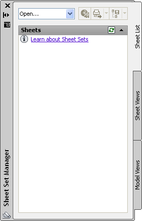
Figure 28-2 Naming a new sheet set
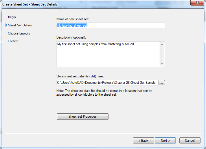
Figure 28-3 Options for importing layouts
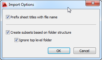
Figure 28-4 Browse to the drawings.
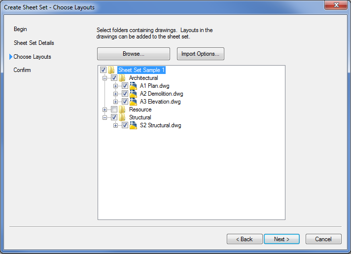
Figure 28-5 The list of drawings
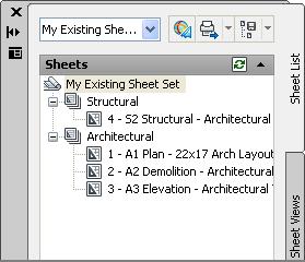
The sheet list in the Sheet Set Manager shows the name of each existing drawing file with the layout name appended. This helps you identify both the filename and the layout associated with the sheet. As you become more familiar with the Sheet Set Manager, you can choose to display only the layout name.
Exploring the Sheet Set Manager
Although you have more work to do before the sheet set becomes a useful tool, it’s complete enough that you can explore some features of the Sheet Set Manager before you add the resource drawings.
Formatting Sheet Sets with the Import Options
In step 9 of the preceding exercise, you saw the Import Options dialog box. This dialog box lets you control how files and folders are organized in the Sheet Set Manager and how the sheets are assigned names. Here is a list of these options:
The sample folders you used for the previous exercise were set up to demonstrate how these options work. All the options were turned on. As a result, the Sheet Set Manager displayed the sheets with two main categories, Architectural and Structural, reflecting the folder structure of the sample project files. The sheet names showed the layout names appended to the drawing filenames because the Prefix Sheet Titles With File Name option was turned on.
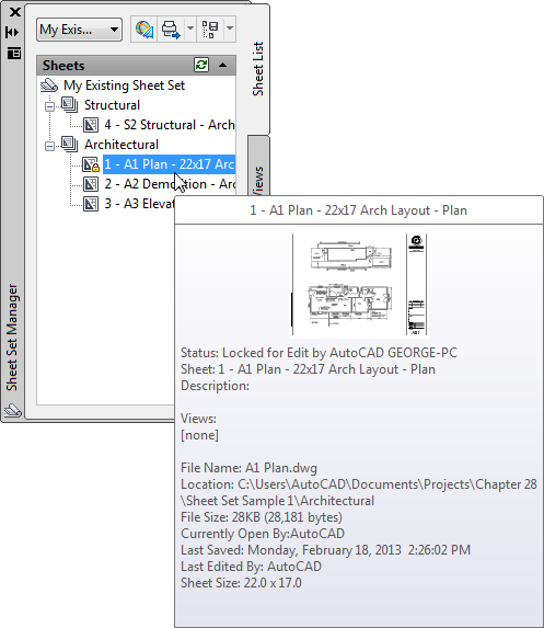
Previewing and Opening Drawings in the Sheet Set Manager
You can view quite a bit of information about the drawings in your list. You can also open a file by double-clicking its name in the sheet list. Here’s how:
Figure 28-6 The flyout information panel
Adding the Resource Drawings
Now you’ll add the resource drawings to the Sheet Set Manager’s sheet list. Remember that the resource drawings are the source Xref files for the sheet drawings. By adding them to the Sheet Set Manager, you’ll have ready access to all the files in your project:
Your sheet set now contains a list of all the files in the project. You can use the Sheet Set Manager to keep track of your AutoCAD files as the project progresses. If you need to plot all your sheets, archive them, or move them, you can do so with relative ease by using options described toward the end of this chapter.
Adding New Sheets to Your Sheet Set
Now that you’ve created a sheet set from an existing project, as the project continues you’ll want to use the Sheet Set Manager to create any new sheets that you want to add to your set. Doing so ensures that the Sheet Set Manager knows about all the files in the project at all times.
But before you start to add new sheets, you need to do a bit of setup. You’ll need to make sure the Sheet Set Manager knows which template file to use for any new sheet drawings you add to the set.
Pointing to a Sheet Template
The following exercise shows you how to tell the Sheet Set Manager which template file to use for new sheets:
C:UsersUser NameAppDataLocal
AutodeskAutoCAD 2014R19.1enu
TemplateSheetSetsArchitectural Imperial.dwtYou’ve just set up your sheet set to point to a custom template that contains the title block for any new sheet files you may create. The last step points out a feature you’ll want to know about.
In this exercise, you set the 22x17 Arch.dwt template file as the file the Sheet Set Manager uses for all new drawings. This template is just a standard AutoCAD template created for this exercise. If you prefer, you can set up the Sheet Set Manager to use different template files for new sheets in the sheet subsets. For example, you can have one template for the Architectural subset and a different one for the Structural subset, if they require different title blocks.
To set up the template for the subsets, follow the steps in the previous exercise, but instead of right-clicking My Existing Sheet Set, select the subset name. In the Sheet Set Sample 1 sheet set, the name would be Architectural or Structural.
Another option is to select the Prompt For Template option near the bottom of the Sheet Set Properties or Subset Properties dialog boxes. As the option name indicates, it prompts you for a template file whenever you create a new sheet.
Adding a New Sheet
You’re ready to create new sheets that are based on the same title block as the existing sheets in the set:
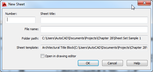
Before you added the new A4 Details sheet, the Sheet Set Manager was only collecting data about your sheet set and displaying that data in the palette. It hadn’t created any new files. In the preceding exercise, the Sheet Set Manager created the A4 Details file from the 22x17 Arch.dwt template file you specified in the previous exercise, although it didn’t open it until you double-clicked it in step 4.
Now that the A4 sheet has been created, you can edit it as you would any other drawing to include Xref files, blocks, or other drawing data. You can then create a viewport in the layout to arrange the sheet the way you want.
In a large project with many sheets, managing title-block information can be a lot of work. In the next section, you’ll look at some other sheet set features that can automate much of the work of maintaining title-block information. You’ll also learn how the Sheet Set Manager can simplify the creation of callout bubbles and cross-references between drawings.
Managing Title Blocks and Cross-References
You’ve just seen that at a basic level, you can use the Sheet Set Manager to keep track of files in a set of drawings. But other features can help reduce the time it takes to create and maintain sheets. In the next section, you’ll look at some of the more advanced sheet set features by creating a sheet set based on an existing one.
The Sheet Set Manager can use specially designed template files to automate the creation and management of your sheets. You can include fields (see Chapter 11, “Using Fields and Tables,” for more on fields) that are sheet set aware, enabling the Sheet Set Manager to update text automatically whenever there is a change in the sheet set. In addition, the Sheet Set Manager can use blocks with field attributes to automate the process of adding drawing titles and reference symbols, called callout blocks, in the Sheet Set Manager. You can customize these templates and callout blocks to fit your style of drawing and method of organization.
Creating a New Sheet Set Based on an Existing One
To see firsthand how the Sheet Set Manager can help you manage title blocks and cross-references, you’ll create a new sheet set based on an existing sample sheet set created by Autodesk. You’ll use a sample sheet set found in the user template folder for new AutoCAD 2014 installations. This sample sheet set uses a template file that has the title block and callout blocks already set up and available for use.
Just as before, you’ll start by opening the Create Sheet Set Wizard. Follow these steps:

Now, if you check your sample file folder, Chapter 28Sheet Set Sample 2, you’ll find the My Sheet Set.dst file that you’ve just created. As you’ve seen in prior steps, this file holds the information regarding the location of the files and custom settings for your sheet set.
The first sheet set you created was from drawings that already had Xrefs and views set up for the sheets. The next section shows you how to use the Sheet Set Manager to create a sheet from scratch, including views and Xrefs.
Building a Set of Drawings
The sheet set you just created is like the framework of your set of plans. It isn’t the actual set of drawings but rather a structure onto which you can start to build your set of drawings. The Sheet Set Manager manages the coordination and continuity of the set as you add sheets to the set.
To see how these drawing components are managed by the Sheet Set Manager, you’ll create some sheets from existing Model Space files. You’ll start by adding a couple of floor plans to the sheet set.
You’ll use the resource drawings that you saw in the first set of exercises in this chapter as the basis for the new sheets.
Setting Up Some Views
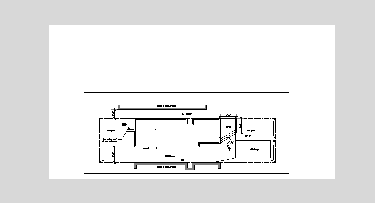
The Sheet Set Manager uses drawing views to help simplify the creation of viewports in a sheet, so you’ll start by creating some views in a plan drawing. These views will define the areas and layer settings that will be needed later when you create the plan sheets. Follow these steps:
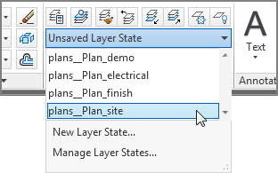
You’ve just restored a layer state that shows all the appropriate layers for the site plan. Next you’ll save a view of just the site plan, which you’ll use a bit later when you create the site plan sheet:

You’ve just created a view for the site plan. Now create another view for the floor plan:
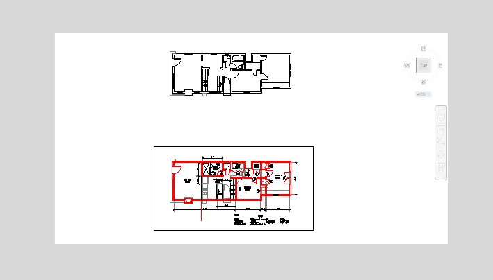
Figure 28-7 Selecting the view area
If you know that you want to use other views for your sheets, you can continue to define more views. But for this exercise, let’s move on to creating a sheet from the views you just created.
Figure 28-8 Selecting the view area
Creating a Sheet
Now that you have some views defined, you’re ready to create a sheet for those views:

If you look closely, you’ll notice that the sheet number is already in place in the lower-right corner of the drawing. The Sheet Set Manager was able to apply the sheet number you entered in step 3 to the new sheet because the template uses a field for the sheet-number text. You’ll learn how to add such a field to your own title block later in this chapter. For now, you’ll add the views you created in the plans.dwg file to this new sheet.
Adding Your Views to the New Sheet
You’ve created views in your plans.dwg resource drawing, and you’ve created a new sheet for the plan views. The next step is to insert those saved views into the sheet.
Start by adding the resource drawings to the sheet set:
With the resource files added to the Sheet Set Manager, you can add a view to the A1 sheet from the plans.dwg file you worked on earlier:
Figure 28-9 Adding and positioning a view
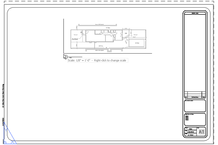
In the preceding exercise, the Sheet Set Manager performed several steps that you could have done manually with much more effort. It imported the plans.dwg file as an Xref into the A1 – Site Plan And Floor Plan layout. It then created a viewport in the layout, it scaled the layout view according to your selections in steps 4 and 7, and finally, it added a title bubble and the title and scale for each view.
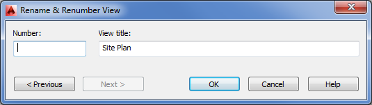
Editing the View Numbers
You need to take care of one more item for this sheet. Although the view names and scales have been provided by the Sheet Set Manager, you still need the view numbers. Right now they’re just three dashes. Follow these steps:
Figure 28-10 The Rename & Renumber View dialog box
The final task is to hide the viewport borders. You can do this by creating a layer just for the viewports and then turning off that layer:
Adding the view numbers is important for two reasons. The obvious one is so that you have a number to which you can refer when referencing this plan sheet in the future. But the Sheet Set Manager also keeps track of this view number so that later, when you start to add callout blocks to your drawing set, the Sheet Set Manager knows which view goes with the callout block you’re adding. The next section will show you how this works.
Adding Callout Blocks as Cross-Reference Symbols
As mentioned earlier, in the process of building a set of drawings, you’ll have to add cross-reference symbols. One common type of cross-reference indicates an elevation view of a building from a floor plan.
In a typical set of architectural drawings, you’ll have a sheet or several sheets that show the sides of a building. The most common views are the north, south, east, and west sides of a building. Elevation drawings are used to indicate window locations, wall finishes, building heights, floor levels, and other key elements in the design. Reference symbols, called callout blocks in AutoCAD, are placed in the floor plan and tell the viewer which sheet contains these elevation drawings and show from where the view is taken in relation to the plan.
In this section, you’ll learn how to set up an elevation view and place callout blocks in the floor plan that show which sheet contains the elevation. You’ll see how callout blocks are tied to sheet numbers so that even if a sheet number changes, the callout block always indicates the right sheet number.
You’ll use a sheet set similar to the one you just started, but with a few additions to save some work for you. The My Sheet Set 1.dst sheet set has the A1 Site Plan And Floor Plan sheet already created and an additional sheet called A2 Elevation Plan. This additional sheet contains two elevation views. They were created in the same way as the plan views in the previous exercise, so no method was used to create them that you haven’t already been shown.
In the following steps, you’ll add a callout block to the A1 sheet that references the A2 sheet. Along the way, you’ll become familiar with some of the other features of the Sheet Set Manager.
Start by closing the current sheet set and the files associated with it:
Next, open the sample sheet set:
Next you’ll add the callout symbol to the A1 sheet. In the next few steps, you will be adding callout symbols based on preexisting views from the A2 Elevations drawing:
Figure 28-11 Enlarge your view, and place the callout blocks as shown.
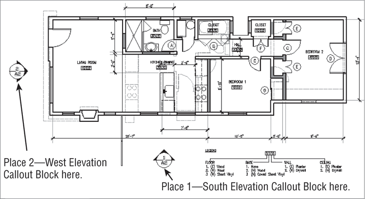
When you inserted the callout blocks in steps 4 through 7, the Sheet Set Manager automatically added the appropriate sheet and view number to the block. This action saves you the effort of checking which drawing contains the elevation view and of making sure the numbers between the callout block and view match.
Editing Sheet Numbers and Title Block Information
Suppose you need to change the sheet number of the elevation sheet from A2 to A3 to make room for a demolition plan. The following exercise demonstrates how the Sheet Set Manager can make quick work of such a change:
As you saw from this exercise, the drawing numbers are coordinated through settings in the Sheet Set Manager as long as you use the callout symbols from the Sheet Set Manager.
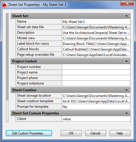
Drawing numbers aren’t the only part that can be managed through the Sheet Set Manager. You have two sheets in the set now, but they were created without regard for the client name and address in the title block. You’ll need to go back and add this information to the sheets. Here’s a quick way to do it:
The changes you made in this exercise affect all the existing sheets in the set. If you add new sheets, they will also display the new address and project name.
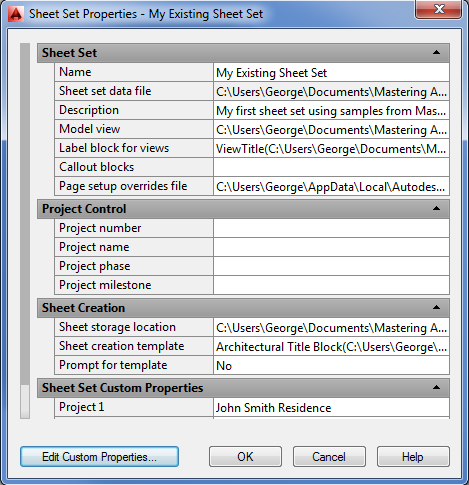
Figure 28-12 Sheet Set Properties
Closing a Sheet Set
By now, you have two sheet sets open: the one you created from an existing set of drawings and the one you opened for the latest set of exercises. In the next sections, you’ll look at customizing sheet sets. You won’t need both sheet sets open. Close the one on which you’ve been working by following these steps:
As you can see, you can have multiple sheet sets open at any one time. This feature can facilitate the movement of drawing data from one project to another. For example, you may want to borrow construction details from one set to add to a new set. You can use the Sheet Set Manager to locate the detail sheet from the prior project and then cut and paste drawing data from that drawing into a drawing in your most current project.
Customizing Sheet Sets
In the preceding sections, you created and used a sheet set that was based on a canned sheet set from Autodesk. That sheet set included a title block with many of the field text objects already embedded so that you could take advantage of the Sheet Set Manager’s ability to control the text in the title block. The view title bubbles and callout blocks were also supplied, and they contained the field text objects to automate the insertion of view names and coordination of callout cross-reference numbers.
But not everyone will want to use the title blocks and symbols offered in the Autodesk samples. You aren’t limited to using the canned sheet set from Autodesk. In the following sections, you’ll look at how to customize your own title block to work with the Sheet Set Manager. You’ll also learn how to create custom view titles and callout blocks.
Customizing a Title Block
To begin your exploration of sheet set customization, you’ll add field objects to the sample title block you used at the beginning of this chapter. Remember that the first project included an existing set of drawings that wasn’t set up to take full advantage of all the sheet set features you saw in the latest set of exercises. The title block in that early exercise contained some attributes that could be used to include text information, but the title block was not sheet set aware. To prepare a title block for use with the Sheet Set Manager, you’ll need to convert those attribute values into field objects. This entails editing the title block and saving it as the template file for the sheet set.
Setting Up Sheet Numbers and Titles
The first thing you’ll do is set up the title block to create a sheet set–aware number and title. Doing so will enable the Sheet Set Manager to control the number and title that appears in the title block, as you saw in earlier exercises.
You could open the template file and start editing the title block without involving the Sheet Set Manager in any way. But now, in the following set of exercises, you’ll edit the template file with a little help from the Sheet Set Manager. By using the Sheet Set Manager while editing your template file, you’ll be able to get instant feedback on your edits.
Start by creating a new sheet in the sheet set you created at the beginning of this chapter. You’ll use this new sheet to edit the title block. Follow these steps:
Remember that a new file based on a template is really just a copy of the template. As we mentioned earlier, the title block is an AutoCAD block that contains attribute definitions. To edit those definitions, you’ll need to explode the block:
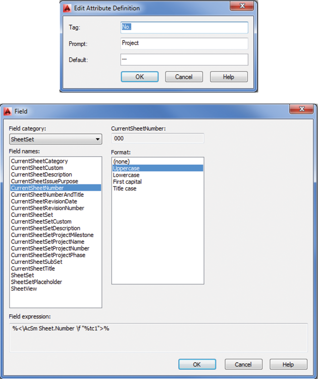
Now you’re ready to edit the attribute definitions. Start by editing the definition for the sheet number in the lower-right corner of the title block:
In step 6, you received instant feedback when you assigned the CurrentSheetNumber attribute field to the attribute definition. The default value changed to the sheet number of the current drawing.
Figure 28-13 Inserting a field in the attributes
Next you’ll make a similar change to add the project name to the title block:
These two exercises demonstrated how you can add a field object to an attribute definition and have that definition give you immediate feedback about its association to the sheet set. In the first case, the default sheet number in the Edit Attribute Definition dialog box reflected the current sheet number. In the second exercise, you saw that the sheet title appeared.
Figure 28-14 Zoom into the project info.
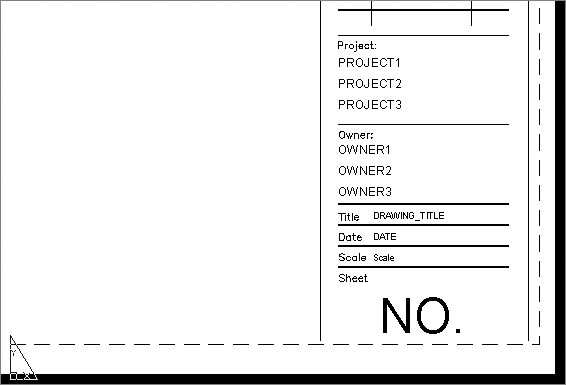
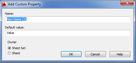
Adding Custom Sheet Set Properties
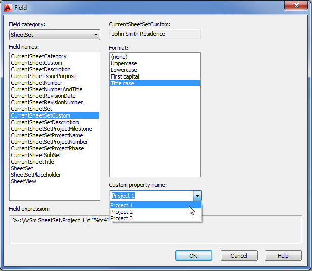
You’ve added two of the standard sheet set fields to the title block. The standard fields are the ones that appear in the Field Names list in the Field dialog box. But what if you want to add custom sheet set fields that aren’t on the list? You can create your own field categories in the Sheet Set Manager. In the following set of exercises, you’ll create some custom fields in the Sheet Set Manager properties dialog box and then add those fields to your title block.
First, set up some new custom fields:
You’ve created some custom properties. Now include those properties in your title block:
Figure 28-15 Choose from the list of field names.
Saving Your New Title Block as a Template
You’ve just seen how to include custom sheet set properties in your title block. Now you’re ready to convert your newly edited title block back into the template file you’re using for this sheet set.
First you need to turn your exploded title block back into an AutoCAD block object:
The title block now shows the sheet number 000. If you look closely, you’ll also see that the sheet title shows Template Edit. These are the name and number you assigned to this sheet when you first created it.
The next task is to save the file as the template file for the current sheet set:
Normally, at this point you could close the newly saved template file and remove the 000 – Template Edit sheet from the sheet list. However, you’ll use this file again when you create other components of the sheet set.
Testing the New Template
Now you can test the new template to make sure it’s working. You’ll start by creating a new sheet to check whether the sheet number and title appear correctly:
You also added some custom sheet set properties. Do the following to see if they’re working properly:
You’ve customized the title block with custom properties and a sheet set–aware number and title. Armed with this information, you can customize any title block to take full advantage of the sheet set features.
You can include a lot of information in the title block through the Sheet Set field option. Table 28-1 gives you a rundown of the sheet set options to help you decide what you may want to include.
Table 28-1: Field options available for sheet sets
| Field name | Purpose |
| CurrentSheetCustom | Displays custom sheet data. Custom sheet data can be added and edited through the Sheet Set Properties dialog box. |
| CurrentSheetDescription | Displays the description for the current sheet found in the properties for the sheet. Select the sheet name from the Sheet Set Manager’s Sheet List tab, right-click, and choose Properties. |
| CurrentSheetNumber | Displays the current sheet number. |
| CurrentSheetNumberAndTitle | Displays the sheet number and title combined into one line of text. |
| CurrentSheetSet | Displays the name of the current sheet set. |
| CurrentSheetSetCustom | Displays a custom value for the current sheet set. |
| CurrentSheetSetDescription | Displays the sheet set description, which can be found in the Sheet Set Properties dialog box. |
| CurrentSheetSetSubSet | Displays the name of a subset of the current sheet set. |
| CurrentSheetTitle | Displays the current sheet title. |
| SheetSet | Displays any standard sheet set value, such as sheet number and title, sheet title, sheet number, or sheet description, from any sheet in the sheet set. |
| SheetSetPlaceholder | Displays standard sheet set values from within callout blocks. |
| SheetView | Displays sheet set view data, such as view title, view number, and view scale. |
| CurrentSheetCategory | Displays a category field. |
| CurrentSheetIssuePurpose | Displays an Issue Purpose field. |
| CurrentSheetRevisionDate | Displays a Revision Date field. |
| CurrentSheetRevisionNumber | Displays a Revision Number field. |
| CurrentSheetProjectMilestone | Displays a Project Milestone field. |
| CurrentSheetProjectName | Displays a Project Name field. |
| CurrentSheetProjectNumber | Displays a Project Number field. |
| CurrentSheetProjectPhase | Displays a Project Phase field. |
Creating Custom View Labels and Callout Blocks
In the section “Managing Title Blocks and Cross-References” earlier in this chapter, you learned how to create a new sheet set from an existing one. You saw that the Sheet Set Manager was able to create a viewport and add a view label automatically, including a view number bubble, a view title, and the scale for the view. Just like the title block, the view label you used in the section “Adding Your Views to the New Sheet” was a block with field attribute values. You can create your own view label block or edit an existing one by using the methods you’ve already seen for the title block. Callout blocks are also created and edited in the same way.
Creating the Components of Your View Label
In this section, you’ll create a custom view label. This will help you to understand which field attributes are used for the view label. You’ll also learn how to set up the Sheet Set Manager to use your custom block.
Just as with the title block, you could create the view label block in AutoCAD without using the Sheet Set Manager, but using the Sheet Set Manager simplifies your work and also helps verify that you’re on the right track. You’ll start by going back to the template file you edited earlier, and then you’ll create the graphics and attribute definitions for your custom view label. Follow these steps:
Figure 28-16 Beginning to create the view label block

Figure 28-17 Defining an attribute
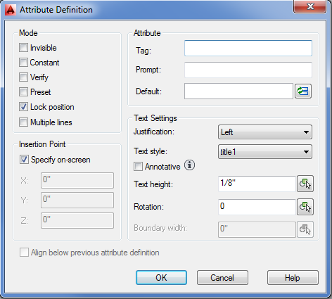
Figure 28-18 Defining the field to insert
If you forgot a setting in the previous steps, you can always go back and use the Properties palette to modify the attribute definition settings. Select the attribute definition, right-click, and choose Properties.
Next you need to add the view title and scale. The steps to add these parts of the view label are the same as for the view number you just added. You first create an attribute definition by using the Insert Field option for the attribute value. The only difference is the location and text options for the attribute definition. Here are the steps:
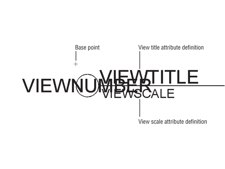
Figure 28-19 The parts of the view label block
Finally, you need to add the scale information to the view title:
Turning the Components into a Block
You have all the attribute definitions you’ll need. The next task is to turn the whole thing into a block:
You may notice that, in step 5, the text in the block obscured the circle and line graphic. Fields always show a gray background to distinguish them from other types of text. The gray background doesn’t print, so even though it appears to cover the line and circle, the fields won’t interfere with the printing of those objects.
Including Your View Label in the Sheet Set
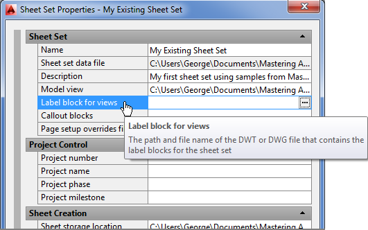
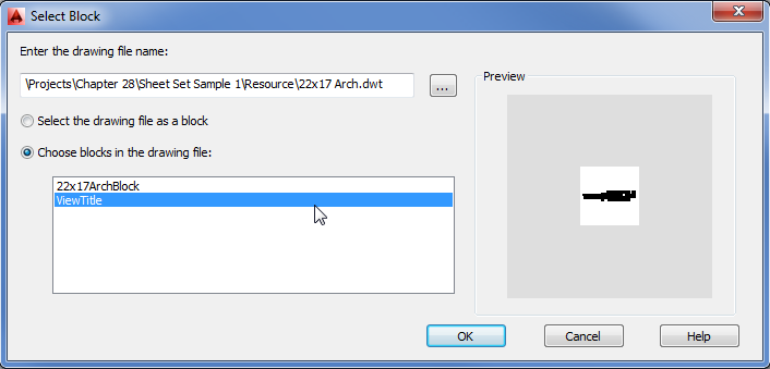
You must complete one more task to let the Sheet Set Manager know that your ViewTitle block is available. To do this, you need to open the Sheet Set Manager Preferences dialog box and point to the ViewTitle block. Here’s how that’s done:
Figure 28-20 Choose to label the block.
Remember that you created the ViewTitle block inside the 22x17 Arch.dwt template file, so when you saved that file, the block became a part of that template file. In steps 4 and 5, you selected the template file and then selected the block in that file. If you prefer, you can save your view title blocks as individual files. If you choose this route, make sure that you select the Select The Drawing File As A Block option in step 4.
Figure 28-21 Set the Select Block options.
Now you’re ready to test the block by adding a sheet and inserting a view. Remember that the Sheet Set Manager uses views to determine the contents of new viewports. Follow these steps:
You’ve seen how to create a custom view label block. The process for creating a callout block is basically the same.
Creating a Callout Block
You may recall that you were able to insert a callout block in a Plan view that was linked to an elevation drawing on another sheet. You can create a custom callout block by using the same steps you used to create the view title block in the preceding section. The only difference is that you select a different set of field values for the block’s attribute definitions.
A callout block typically shows a circle with a view number on top and a sheet number on the bottom, as shown in Figure 28-22.
Figure 28-22 A typical callout block inserted in a drawing
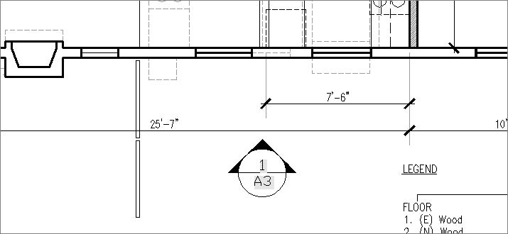
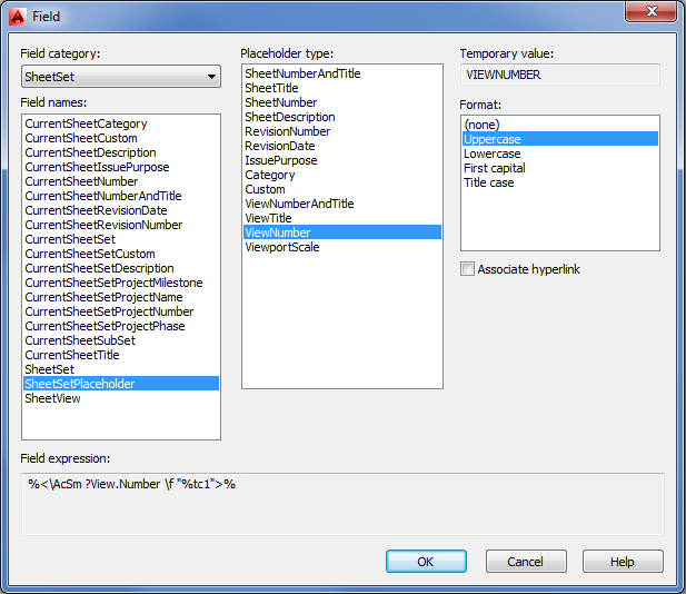
Figure 28-23 shows an exploded version of the callout block with the attribute definitions labeled with the appropriate field values. Those field values are found under the SheetSetPlaceholder field names in the Field dialog box.
Figure 28-23 The attribute definitions of a callout block and their associated field values

In addition, you’ll want to select the Associate Hyperlink option in the Field dialog box (see Figure 28-24).
Figure 28-24 Choose to create a hyperlink.
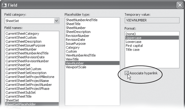
With this option selected, a hyperlink is created between the callout block and the view associated with it. This hyperlink will enable you to go directly to the sheet and the view being referenced by the callout block by Ctrl+clicking the field value in the callout block.
Just as with the view title block, you can include the callout block inside the template file, or you can create individual files for each of your callout blocks. You can also have several callout blocks for different purposes.
For example, in the My Sample Sheet Set you created toward the beginning of this chapter, several callout blocks were available in the View List context menu (see Figure 28-25).
Figure 28-25 Choose a callout block.
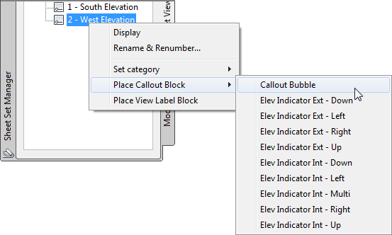
In that example, there was a callout block for the arrow directions. You can create a similar set of callout blocks for your drawings. You can also include callout blocks for details and finishes. You can even invent some uses on your own.
Reviewing the Steps for Creating Custom Callout and View Label Blocks
The callout block and view label feature will save you a lot of time when you’re building your set of drawings, but you must go through a lot of steps when creating them. To help you get a better overall grasp of the process, here is a checklist of the general steps you need to take:
- Create the graphics for the callout blocks.
- Create the attribute definitions for the text in the callout blocks.
- Assign the appropriate fields for the attribute definition values. For callout blocks and view titles, this is usually a SheetSetPlaceholder field.
- Convert the graphics and attribute definitions into a block. Place the insertion point of view title blocks in the upper-left corner of the block to coincide with the location of the lower-left corner of the viewport with which it will be associated.
- Use the Sheet Set Properties dialog box to indicate the file location of your callout and view title blocks. These can be blocks in a file or individual files.
Also remember to turn on the Associate Hyperlink option when selecting the fields for your callout blocks.
Archiving, Publishing, and eTransmitting Sheet Sets
The sheet set feature is a great way to keep your project files organized while you’re creating your drawings. You can also use the Sheet Set Manager to turn your set into a package that can be easily sent to others who may need to work on the drawings or view them. And you can use the Sheet Set Manager to create an archive of your set for safekeeping at the end of the project.
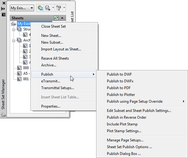
You may have noticed that the Sheet Set context menu contains several options. Right-click the main title of your sheet set in the Sheet Set Manager’s sheet list and you see the Archive, Publish, and eTransmit options:
- The Archive option lets you collect your sheet set files into a Zip archive file.
- The Publish option offers a convenient way to convert your set into a format that can be easily read by others who don’t have AutoCAD.
- The eTransmit option offers a way to transport your sheet set easily to others who may need to work on the set.
In the following sections, you’ll take a closer look at these three sets of features for sharing your sheet set.
Archiving Your Sheet Set
One of the most important housekeeping jobs you’ll do is archiving completed projects. If you organize your projects by folders, you could archive the entire folder for a project, but in so doing, you might archive many files that weren’t part of the set.
The sheet set Archive option lets you be more selective about the files you archive. You can exclude files in the sheet set or include other files that aren’t necessarily AutoCAD drawings.
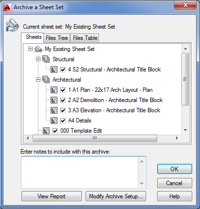
When you’re ready to archive your sheet set, save all the files in your archive and then open the Archive dialog box. To do this, right-click the name of your sheet set in the Sheet List tab of the Sheet Set Manager and choose Archive from the context menu to open the Archive A Sheet Set dialog box (see Figure 28-26).
The Archive A Sheet Set dialog box has three tabs. On the Sheets tab, the check boxes by the sheet names indicate the sheets that will be archived. If you decide that you want to leave a sheet out of the archive, you can remove the check mark. The unchecked file and its associated Xref aren’t archived.
The Files Tree tab offers a slightly different view of the archive. Instead of just showing you the sheet names, the Files Tree tab shows you the names of the files that will be archived. These include support files such as the sheet set data file and the template file associated with the sheet set.
The Files Table tab shows you even more detail about the files that will be archived, such as the path, the AutoCAD version, and similar information. It also includes information about the resource files that are Xrefs in the sheet files.
In both the Files Tree and Files Table tabs, the Add A File button enables you to include other files with the archive that aren’t necessarily AutoCAD related but are part of the overall project. You can use this option to include Excel or Word documents that represent correspondence or worksheets.
Figure 28-26 Archiving a sheet set
Modifying the Archive Setup
By default, the sheet set Archive feature saves files in the Zip archive format (.zip filename extension). You can change the way the archives are saved as well as the location of the archive, the archive name, and several other settings through the Modify Archive Setup dialog box.
Click the Modify Archive Setup button in the Archive A Sheet Set dialog box to open the Modify Archive Setup dialog box (see Figure 28-27).
Figure 28-27 Editing the archive setup
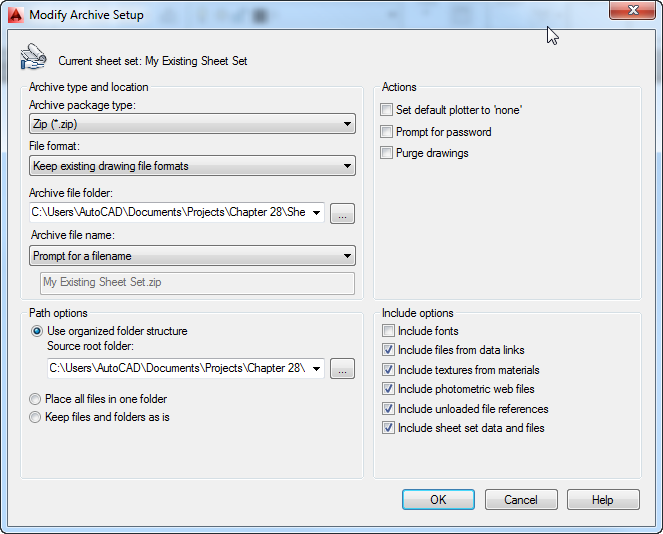
Here you can make adjustments to the properties of the archive file, including the type of file to create and whether to preserve the file structure.
Saving the Vital Statistics of Your Archive
You can also view and save pertinent information about your archived sheet set by clicking the View Report button in the Archive A Sheet Set dialog box. Clicking this button opens the View Archive Report dialog box.
You can view the vital statistics regarding your sheet set archive. You also have the option to save the information in a file by clicking the Save As button. This opens a standard save file dialog box where you can assign a name and location for the information file. It’s stored as a plain-text file with the .txt filename extension.
Batch-Plotting and Publishing Your Sheet Set
Another advantage of using sheet sets is that you can print all the sheets in a set at once and in the background. The Publish option in the Sheet Set context menu enables you to turn the Sheet Set Manager into a batch-plot utility.
When you right-click the sheet set title in the sheet list of the Sheet Set Manager, you see the Publish option. Click Publish and another set of options appears (see Figure 28-28), offering several plotting and publishing options.
Figure 28-28 Options for publishing
The following list gives a rundown of these options. More detailed descriptions are offered in Chapter 8, “Introducing Printing, Plotting, and Layouts,” and Chapter 27, “Managing and Sharing Your Drawings.” See Bonus Chapter 3, “Hardware and Software Tips,” for more on plot stamps.
Packaging Sheet Sets with eTransmit
In Chapter 27, you learned that you can use the eTransmit feature to package a set of AutoCAD files into a Zip file in order to send the files to someone else who may need to edit them. eTransmit is similar to the sheet set Archive feature, but it also makes sure that all the supporting files, including fonts, font maps, and plotter configuration files, are included in the Zip file.
When you select eTransmit from the Sheet Set context menu, the list of files to include in the eTransmit file is automatically populated with the files from the current sheet set. This means that you don’t have to build the list of drawings manually for the eTransmit file.
If you need to make setting changes for the eTransmit feature, you can do so by selecting the Transmittal Setups option in the sheet set context menu.
Preparing Your Project Files
Now that you’ve seen how sheet sets work, you can start to use them on your own projects. Sheet sets work best when your project files are organized and you have some additional files prepared and on hand. Here’s a checklist of things to keep in mind when you start to use sheet sets:
- Organize your files so that when you import your project into a sheet set, the files will be automatically organized by discipline or sheet number.
- Use only one layout per sheet set drawing file. The Sheet Set Manager uses only one drawing per sheet and one layout per drawing.
- Create a template file containing the title block that you want to use for your project. Be sure to include any sheet set fields you want to use in the title block attribute definitions. You can also include your callout blocks in the template file for convenience.
- Because all the sheets in your project will most likely be printed on the same size sheet with the same plot specifications, it helps to create a sheet setup that you can apply to all your sheets. You can store the sheet setup in any drawing file and then use the Sheet Set Properties option to locate that file to assign the page setup to the entire sheet set.