
Part 1
The Basics
- Chapter 1: Exploring the Interface
- Chapter 2: Creating Your First Drawing
- Chapter 3: Setting Up and Using the Drafting Tools
- Chapter 4: Organizing Objects with Blocks and Groups
- Chapter 5: Keeping Track of Layers and Blocks
Chapter 1
Exploring the Interface
Before you can start to use the new capabilities of the AutoCAD® 2014 software, you must become familiar with the basics. If you’re completely new to AutoCAD, you’ll want to read this first chapter carefully. It introduces you to many basic operations of AutoCAD, such as opening and closing files, getting a close-up look at part of a drawing, and changing a drawing. If you’re familiar with earlier versions of AutoCAD, you should review this chapter anyway to get acquainted with the features you haven’t already used.
Autodesk releases new versions of AutoCAD every year. Part of this strategy is to introduce improvements that focus on a particular category of features. This latest version, AutoCAD 2014, includes new and improved features that are related to the command input and GIS.
The command line has been beefed up to be more interactive and intuitive. It offers an autocorrect feature and can display suggestions, much like the way some popular web browsers work.
The ability to make objects appear transparent has also been improved.
Autodesk has discovered that the number of users making use of point cloud scanning is on the upswing, so with this version, you’ll see some new features that will allow you to make smoother use of real-world references with point clouds, with controls similar to those in other referenced files. A new adjunct program called ReCap is available to help you import point cloud data into AutoCAD. You’ll get a chance to explore these new features and many more as you work through this book.
Before you begin the exercise later in this chapter, make sure that you have loaded the sample files from this book’s web page at http://www.sybex.com/go/masteringautocad2014. See the introduction for details. If you have purchased the e-book version, please see the introduction for instructions on how to download the sample files.
In this chapter, you will learn to:
- Use the AutoCAD window
- Get a closer look with the Zoom command
- Save a file as you work
- Make changes and open multiple files
Taking a Guided Tour
First, you’ll get a chance to familiarize yourself with the AutoCAD screen and how you communicate with AutoCAD. As you do the exercises in this chapter, you’ll also get a feel for how to work with this book. Don’t worry about understanding or remembering everything you see in this chapter. You’ll get plenty of opportunities to probe the finer details of the program as you work through the later chapters. To help you remember the material, we have included a brief set of questions at the end of each chapter. For now, just enjoy your first excursion into AutoCAD.
Launching AutoCAD
If you’ve already installed AutoCAD (see Appendix B, “Installing and Setting Up AutoCAD”) and are ready to jump in and take a look, proceed with the following steps to launch the program:
If you’re using the trial version, you’ll see the Product License Activation window before step 2. This window shows you the number of days you have left in the trial version. It also enables you to activate the product if you purchase a license. Click the Try button to continue opening the program. Now let’s look at the AutoCAD window in detail. Don’t worry if it seems like a lot of information. You don’t have to memorize it, but by looking at all the parts, you’ll be aware of what is available in a general way.
The AutoCAD Window
The AutoCAD program window is divided into several parts:
- Application menu
- Quick Access toolbar
- InfoCenter
- Ribbon
- Drawing tabs
- Drawing area
- UCS icon (User Coordinate System icon)
- Viewport Controls
- ViewCube®
- Navigation bar
- Command window
- Status bar
Figure 1-1 shows a typical layout of the AutoCAD program window. You can organize the AutoCAD window into any arrangement you want and save it as a workspace. You can save and recall a workspace at any time using the Workspace Switching tool in the Quick Access toolbar. (You’ll learn more about this tool in the next chapter.) The default workspace in Figure 1-1 is called the Drafting & Annotation workspace and is one of several workspaces built into AutoCAD.
Figure 1-1 A typical arrangement of the elements in the AutoCAD window
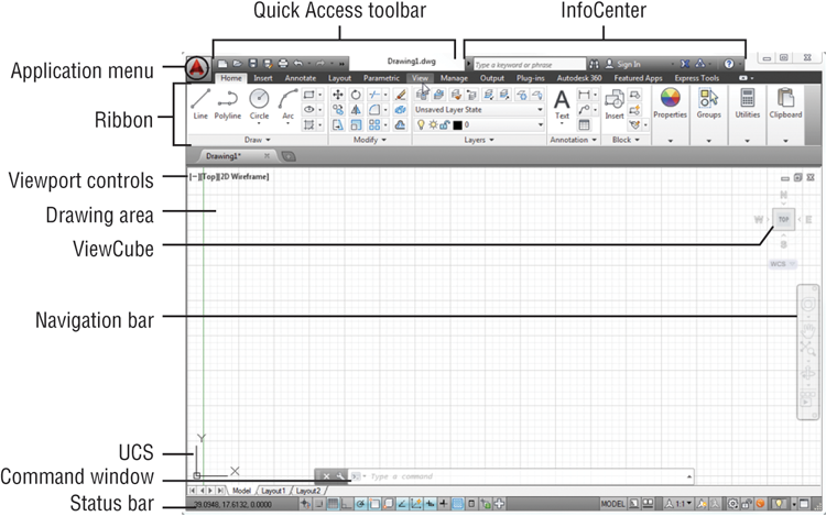
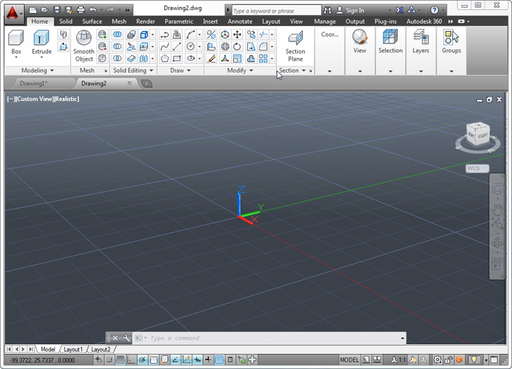
Figure 1-2 shows the AutoCAD 3D Modeling workspace, which has a different set of Ribbon panels. It also shows an AutoCAD drawing file using one of the 3D modeling templates in AutoCAD. Beneath these external changes, the underlying program is the same.
Figure 1-2 The 3D Modeling workspace offers an alternative set of menus whereas the 3D drawing template displays the drawing space in 3D.
You’ll learn more about workspaces and templates later in this chapter and in Chapter 26, “Customizing Toolbars, Menus, Linetypes, and Hatch Patterns.”
In the upper-left corner of the AutoCAD program window, the red AutoCAD icon displays the Application menu, which offers a set of options not directly related to drawing; we’ll elaborate on this menu in the next section. The Quick Access toolbar at the top of the drawing area (shown in Figure 1-3) includes the basic file-handling functions that you find in nearly all Windows programs. The InfoCenter is the AutoCAD online help facility; you’ll learn more about it in Chapter 2, “Creating Your First Drawing.” The Ribbon uses icons to provide nearly all the commands you’ll need; you’ll learn more about it in the section “Using the Ribbon” later in this chapter.
Figure 1-3 The Quick Access toolbar, featuring basic Windows file-handling functions, appears above the Ribbon.
The drawing area occupies most of the screen. Everything you draw appears in this area. As you move your mouse around, crosshairs appear to move within the drawing area. This is the drawing cursor that lets you point to locations in the drawing area. You’ll get your first chance to work with the drawing area later, in the section “Picking Points in the Drawing Area.”
Just above the drawing area are the Drawing tabs that let you create new drawings or switch between open drawings in a way similar to popular web browsers. Notice the “x” in the current tab that lets you close the current drawing, and the plus icon just to the right of the tab that lets you create a new drawing or open an existing one. When you click the plus icon, the Select Template dialog box appears, allowing you to start a new drawing. Right-click on the plus icon, and a context menu opens that offers you the option to open an existing drawing, to save all of the currently open drawings, or to close all of the drawings.
If you hover over the Drawing tab, you’ll see preview images of the model and layouts of the drawing. You’ll learn more about model and layout spaces later in this chapter.
Within the drawing area, you see several items along the side and in the corners. The UCS icon appears in the lower-left corner. You’ll learn more about the UCS icon in a moment (see the section “Using the UCS Icon”). In the upper-right corner, you see the ViewCube. The ViewCube is primarily for 3D modeling, and you’ll learn more about it in Chapter 21, “Creating 3D Drawings.” You’ll also see a Navigation bar along the right edge of the AutoCAD window. This bar offers tools you can use to get around in your drawing. Basic tools like Zoom and Pan can be found here as well as some advanced tools for viewing 3D models.
The Viewport controls in the upper-left corner of the drawing area offer menu options to control 3D and 2D views and visual styles and duplicate some of the functions of the ViewCube. You’ll learn more about the Viewport controls when you explore 3D modeling in Chapter 25, “Exploring 3D Mesh and Surface Modeling.”
Just below the drawing area in the lower-left corner are the Model and Layout tabs. These tabs enable you to switch quickly between different types of views called the model and layout views. You’ll get to see firsthand how these work in a section called “Working with AutoCAD” later in this chapter.
The Command window, located just below the drawing area, gives you feedback about the AutoCAD commands as you use them. You can move and resize this window just as you move and resize other display components. By default, the Command window is in its undocked position, as shown in Figure 1-4. We’ll elaborate on the Command window in the section “Working in the Command Window” later in this chapter.
Figure 1-4 The Command window and the status bar
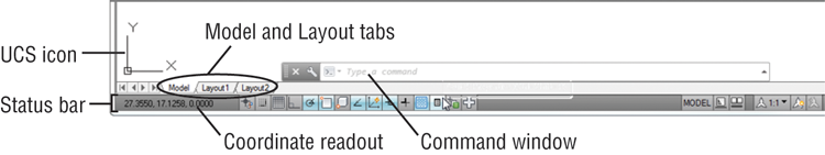
Below the Command window is the status bar (also shown in Figure 1-4). The status bar gives you information at a glance about the state of the drawing. For example, the coordinate readout at the far left of the status bar tells you the location of your cursor. The tools in the status bar offer aids to the drafting process.
Using the Application Menu
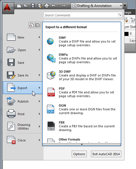
The Application menu offers tools to help you manage your AutoCAD files. It is basically the File pull-down menu from previous versions of AutoCAD. Try it out to see how it works:
Figure 1-5 The Export option in the Application menu showing the list of export options
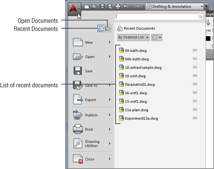
The Application menu also gives you a convenient way to find recently used files or to get to a file you already have open. If you move your cursor away from the list of options to the left in the Application menu, you’ll see Recent Documents in the upper-left portion of the menu. You’ll also see two icon tools, named Open Documents and Recent Documents (see Figure 1-6).
The Open Documents option lets you quickly change from one open file to another when you are viewing your files full-screen. The Recent Documents option displays a list of documents on which you’ve recently worked.
You can use the View tool in the upper-right portion of the Application menu to select the way the list of files is displayed in a manner similar to the way you would use the Windows Explorer View option. You can click this icon and select Small Images to have the list display the files with thumbnail images of their content. Hover over a filename and you will see a tool tip that displays a larger thumbnail of the drawing.
Figure 1-6 The Open Documents and Recent Documents tools
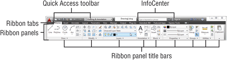
Using the Ribbon
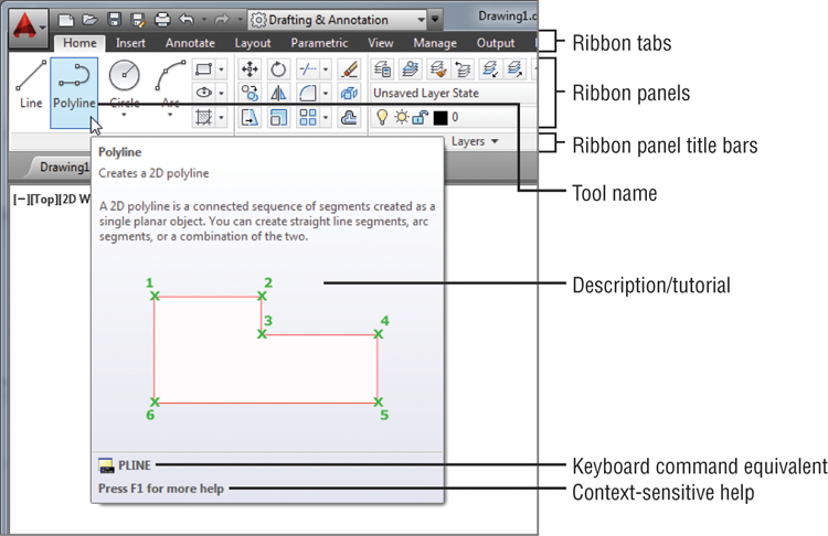
The most prominent feature in the AutoCAD window, besides the drawing area, is the Ribbon (see Figure 1-7). This is where you’ll be selecting tools to draw, edit, or perform other functions. The Ribbon contains a set of panels representing groups of tools and features. The name of each Ribbon panel is found in its title bar at the bottom of the panel. Ribbon panels are further organized by the tabs that appear above them. Each tool in the Ribbon offers a tool tip and cue card that provides a short description to help you understand what the tool icon represents.
Figure 1-7 A typical cue card from a Ribbon panel tool
If you see only the Ribbon tabs, click the arrowhead button in the Ribbon Control tool. If you don’t even see the tabs, type Ribbon↵.
Move the arrow cursor onto one of the Ribbon panel tools and leave it there for a moment; you’ll see a tool tip appear just below the cursor. Hold the cursor there a bit longer and the tool tip changes to give you even more information about the tool.
In most cases, you’ll be able to guess what each tool does by looking at its icon. The icon with an arc in the Draw Ribbon panel, for instance, indicates that the tool draws arcs; the one with the circle shows that the tool draws circles; and so on. For further clarification, the tool tip gives you the name of the tool.
As a new user, you’ll find these tool tips helpful because they show you the name of the tool and a brief description of how to use it. Typically, when we ask you to select a tool, we’ll use the name shown in the tool tip to help you identify the tool. In the case of a tool with flyouts, the tool name changes under different conditions. For those tools, we’ll use a general description to identify the tool. You’ll learn more about flyouts a bit later in this chapter (see the section “Understanding Flyouts”).
As you work through this book, we’ll ask you to select tools from the Ribbon panels. You’ll often be asked to switch between different tabs to select tools from other sets of panels. To make the process simpler to read, we’ll use a somewhat abbreviated description of a tool’s location. For example, for the Line tool we’ll say, “Click the Line tool in the Home tab’s Draw panel.” For the Move tool, we’ll say, “Click the Move tool in the Home tab’s Modify panel.”
Expanding Hidden Panels
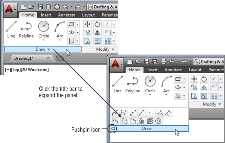
In addition to the visible tools, there are buttons that are hidden from view. You can expand many of the Ribbon panels to select more of them. If you see an arrowhead to the right of a panel’s title bar, you can click the title bar to expand the panel (see Figure 1-8). The panel expands to reveal additional tools. If you move the cursor to the drawing area, the expanded panel shrinks to its original size. You can also click the pushpin icon in the expanded panel title bar to lock the panel in its open position.
Figure 1-8 The arrowhead in the panel title bar tells you that additional tools are available.
From now on, we’ll refer to the location of additional tools as the expanded panel. For example, we’ll say, “Click the Ray tool in the expanded Draw panel” when we want you to select the Ray tool.
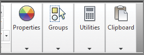
If you are working on a smaller screen with low resolution, some of the Ribbon panels to the far right may look different from what you are shown in this book. On a low-resolution screen, AutoCAD will automatically reduce the size of the panels to the right of the Ribbon so that they show only their title (see Figure 1-9).
Figure 1-9 The Properties, Groups, Utilities, and Clipboard panels are reduced to single icons with a smaller AutoCAD window.
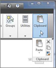
To see the tools, hover over the panel (see Figure 1-10).
Figure 1-10 Hover over the panel to see the tools.
Finally, the Workspace drop-down menu in the Quick Access toolbar may be hidden from view in a low-resolution display. If you don’t see these options in your AutoCAD window, click the double arrowhead icon to the far right of the Quick Access toolbar to reveal it.
Understanding Flyouts
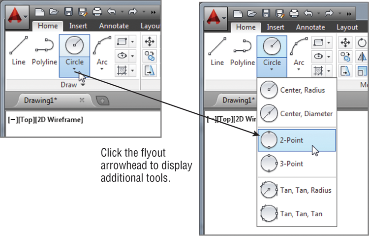
The flyouts are one more feature you’ll want to know about. Flyouts are similar to the expanded panels because you can click an arrowhead to gain access to additional tools. Unlike a whole panel, however, flyouts give you access to different methods for using a particular tool. For example, AutoCAD lets you draw circles in several ways, so it offers a flyout for the Circle tool in the Home tab’s Draw panel. If you click the arrowhead below the Circle icon in the Draw panel, you’ll see additional tools for drawing circles (see Figure 1-11).
Figure 1-11 Flyouts
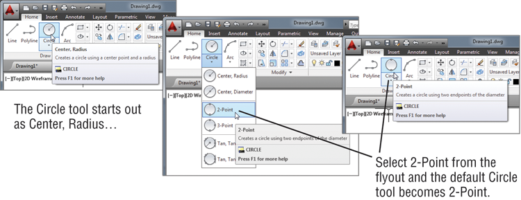
If you select a tool option from a flyout, that option becomes the default tool for the icon you chose. For example, if you hover your cursor over the Circle icon in the Draw panel, you’ll see that the tool tip shows “Center, Radius” for the tool’s name. If you click the arrowhead below the Center, Radius tool and select 2-Point, then 2-Point becomes the default tool and you’ll see “2-Point” for the name of the tool in the tool tip (see Figure 1-12).
Figure 1-12 The tool with a flyout will change to the last tool used.

Picking Points in the Drawing Area
Now that you’ve seen the general layout of AutoCAD, take a look at the coordinate readout and the drawing cursor to get a sense of how the parts of the AutoCAD screen work together:
Figure 1-13 The Dynamic Input display cursor

If you happen to click the right mouse button, a context menu appears. A right-click frequently opens a menu containing options that are context sensitive. This means the contents of the menu depend on the location where you right-click as well as the command that is active at the time. If there are no appropriate options at the time of the right-click, AutoCAD treats the right-click as an Enter (↵) keystroke. You’ll learn more about these options as you progress through the book. For now, if you happen to open this menu by accident, press the Esc key to close it.
Using the UCS Icon
In the lower-left corner of the drawing area, you see an L-shaped line. This is the User Coordinate System (UCS) icon, which tells you your orientation in the drawing. This icon becomes helpful as you start to work with complex 2D drawings and 3D models. The X and Y indicate the x- and y-axes of your drawing. Chapter 22, “Using Advanced 3D Features,” discusses this icon in detail. For now, you can use it as a reference to tell you the direction of the axes.

Working in the Command Window
As mentioned, at the bottom of the screen, just above the status bar, is a small horizontal window called the Command window. Here, AutoCAD displays responses to your input while you’re using a command. By default, it shows one line of text. This line shows the current responses to your command input as well as command options. As you work through a command, you’ll see more responses, with earlier responses scrolling upward in faded text. You can view text that has scrolled out of sight by clicking the upward pointing arrowhead at the far right of the Command window. Right now, the command line displays the words “Type a command” in a box (see Figure 1-4, earlier in this chapter). This tells you that AutoCAD is waiting for a command. When you click a point in the drawing area, you see the message Specify opposite corner:. At the same time, the cursor starts to draw a window selection that disappears when you click another point. The same message appears in the Dynamic Input display at the cursor.
As a new user, pay special attention to messages displayed in the Command window and the Dynamic Input display because this is how AutoCAD communicates with you. Besides giving you messages, the Command window records your activity within AutoCAD. You can use the scroll bar to the right of the Command window to review previous messages. You can also enlarge the window for a better view. (Chapter 2 discusses these components in more detail.)
Now, let’s look at the AutoCAD window components in detail.
Working with AutoCAD
Now that you’ve been introduced to the AutoCAD window, you’re ready to try using a few AutoCAD commands. First you’ll open a sample file and make a few modifications to it. In the process, you’ll become familiar with common methods of operation in AutoCAD.
Opening an Existing File
In this exercise, you’ll get a chance to see and use a typical Select File dialog box.
Before you start, make sure you have installed the sample files for this book from the book’s web page. See the introduction for instructions on how to find the sample files.
To start, you’ll open an existing file:
Figure 1-14 The Select File dialog box
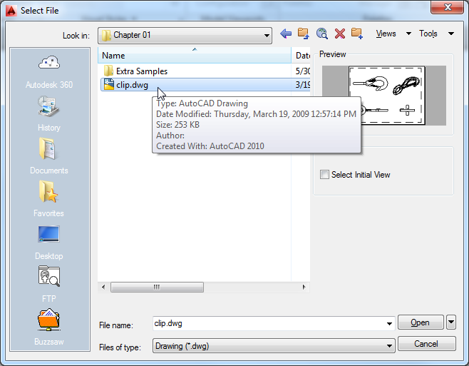
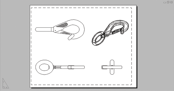
The clip.dwg file opens to display a layout view of the drawing. A layout is a type of view in which you lay out different views of your drawing in preparation for printing. You can tell you are in a layout view by the white area over the gray background. This white area represents your drawing on a printed page. This view is like a print preview.
Figure 1-15 The Layout1 view of the clip.dwg file
Also note that the AutoCAD window’s title bar displays the name of the drawing. The name is also displayed in the Drawing tab. This offers easy identification of the file.
This particular file contains both 2D drawings and a 3D model of a typical locking clip. The layout view shows top, front, and right-side views as well as an isometric view.
Getting a Closer Look
One of the most frequently used commands is Zoom, which gives you a closer look at part of your drawing. This command offers a variety of ways to control your view. In this section, you’ll enlarge a portion of the clip drawing to get a more detailed look. You use a zoom window to tell AutoCAD which area you want to enlarge.
You’ll start by switching to a Model Space view of the drawing. The Model Space view places you in a workspace where you do most of your drawing creation and editing. Follow these steps:
Figure 1-16 Hover over the Drawing tab and click the Model Space image (left) or click the Model tab in the lower-left corner of the drawing area (right).
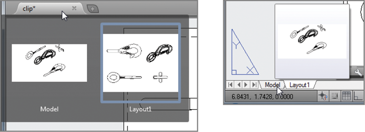
Figure 1-17 D model with 2D representations of the model
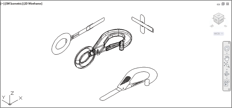
Figure 1-18 Placing the zoom window around the clip
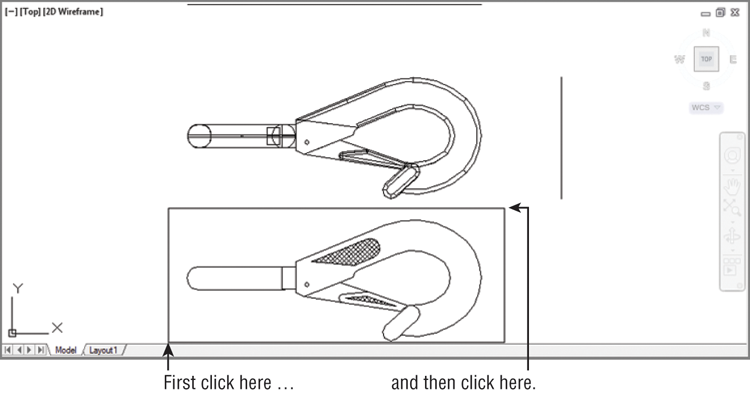
Figure 1-19 Choosing the Zoom Window tool from the Zoom flyout in the Navigation bar
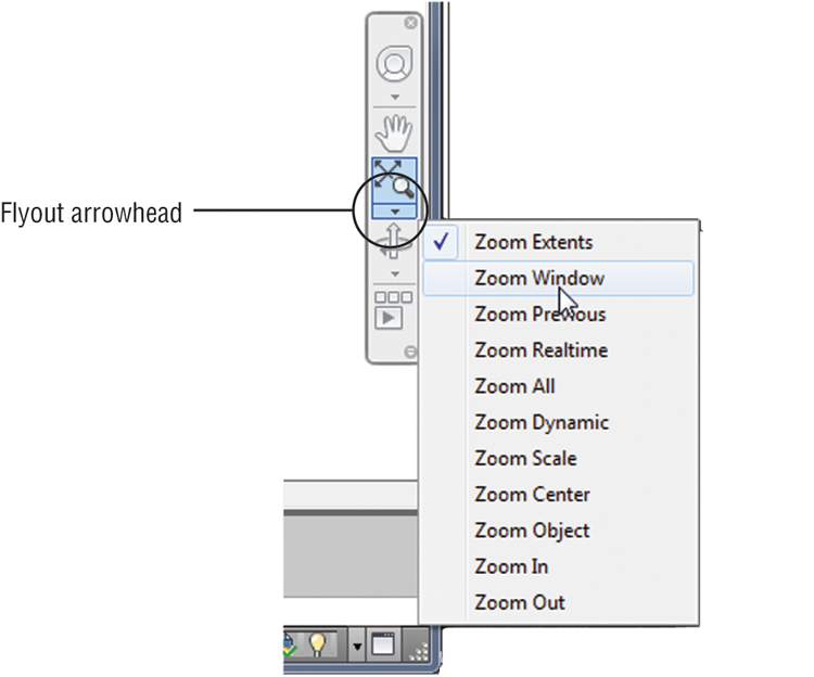
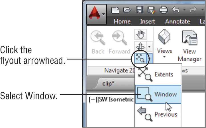
Figure 1-20 The Zoom flyout and Window tool in the View tab’s Navigate 2D panel
In this exercise, you used the Window option of the Zoom command to define an area to enlarge for your close-up view. You saw how AutoCAD prompts you to indicate first one corner of the window selection and then the other. These messages are helpful for first-time users of AutoCAD. You’ll use the Window option frequently—not just to define views but also to select objects for editing.
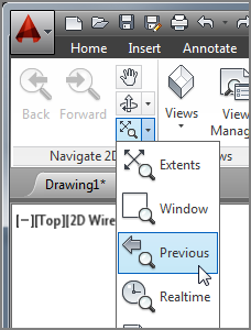
Getting a close-up view of your drawing is crucial to working accurately, but you’ll often want to return to a previous view to get the overall picture. To do so, choose Zoom Previous from the Zoom flyout in the Navigation bar (see Figure 1-21). You may also type Z↵P↵.
Figure 1-21 The Zoom Previous option
Do this now and the previous view appears. Click Zoom Previous again and the view showing the entire clip returns to the screen.
You can quickly enlarge or reduce your view by using the Zoom Realtime option of the Zoom command. Follow these steps to change your view with Zoom Realtime:
Figure 1-22 The final view you want to achieve in step 3 of the exercise
If you prefer, you can use the wheel on your mouse to zoom and pan over your view. Roll the wheel to zoom in and out or click and drag the wheel to pan. Be aware that Zoom Realtime offers finer control over the amount of magnification than the mouse wheel does.
As you can see from this exercise, you have a wide range of options for viewing your drawings just by using a few tools. These tools are all you need to control the display of 2D drawings.
Saving a File as You Work
It’s a good idea to save your file periodically as you work on it. As with any Windows program, you can save it under its original name (click the Save tool on the Quick Access toolbar) or under a different name (choose Save As from the Application menu or the Quick Access toolbar), thereby creating a new file.
By default, AutoCAD automatically saves your work at 10-minute intervals under a name that is a combination of the current filename plus a number and that ends with the .sv$ filename extension; this is known as the Automatic Save feature. Using settings in the Options dialog box or system variables, you can change the name of the autosaved file and control the time between autosaves. See “The Open and Save Tab” in Appendix B for details.
Making Changes
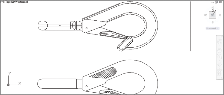
You’ll frequently make changes to your drawings. One of the primary advantages of AutoCAD is the ease with which you can make modifications. The following exercise shows you a typical sequence of operations involved in changing a drawing:
Figure 1-23 Erasing a portion of the clip
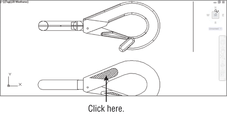
In this exercise, first you issued the Erase command and then you selected an object by using a pickbox to click it. The pickbox tells you that you must select items on the screen, and it shows you what you’re about to select by highlighting objects as you hover the cursor over them. Once you’ve clicked an object or a set of objects, press ↵ to move on to the next step. This sequence of steps is common to many of the commands you’ll work with in AutoCAD.
You can also click an object or a set of objects and then press the Delete key.
Working with Multiple Files
You can have multiple documents open at the same time in AutoCAD. This feature can be especially helpful if you want to exchange parts of drawings between files or if you want another file open for reference. Try the following exercise to see how multiple documents work in AutoCAD:
When you create a new file in AutoCAD, you’re actually opening a copy of a template file, as you saw in step 1. A template file is a blank file that is set up for specific drawing types. The acad.dwt file is a generic template set up for Imperial measurements. Another template file, called acadiso.dwt, is a generic template useful for metric measurements. Other templates are set up for specific drawing-sheet sizes and measurement systems. You’ll learn more about templates in Chapter 6, “Editing and Reusing Data to Work Efficiently.”
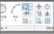
Next, let’s try drawing a rectangle to see how AutoCAD behaves while drawing objects:
Figure 1-24 Click the Rectangle tool in the Draw panel.
Specify first corner point or
[Chamfer/Elevation/Fillet/Thickness/Width]:Specify other corner point or [Area/Dimensions/Rotation]:Figure 1-25 Selecting the first point of a rectangle
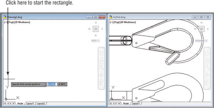
Figure 1-26 After you’ve selected the first point of the rectangle, you’ll see a rectangle follow the motion of your mouse.
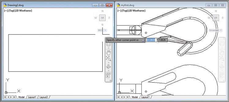
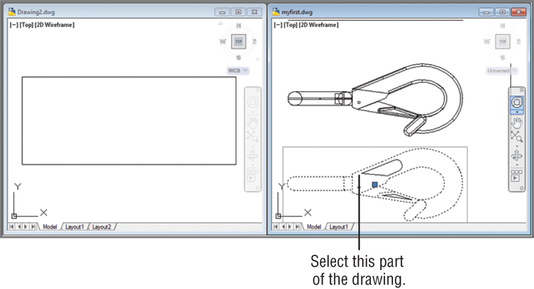
Figure 1-27 The Zoom All option gives you an overall view of your drawing.
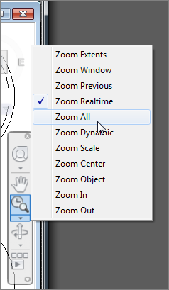
Figure 1-28 Grip shown in the 2D drawing
Note that you’ve had two files open at once. You can have as many files open as you want as long as your computer has adequate memory to accommodate them. You can control the individual document windows as you would any window, using the window control buttons in the upper-right corner of the drawing area.
Adding a Predrawn Symbol with the Tool Palettes
In the preceding exercise, you saw how you can easily copy an object from one file to another by using the standard Windows Cut and Paste feature. AutoCAD offers several tool palettes that enable you to click and drag predrawn objects into your drawing.
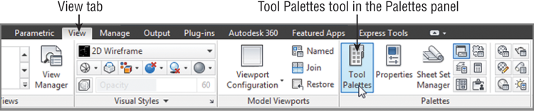
You can open the tool palettes by clicking the Tool Palettes tool in the Interface tab’s Palettes panel, as shown in Figure 1-29.
Figure 1-29 Open the Tool Palettes from the View tab.
Once the tool palettes are open, you can select a tab in the tool palettes containing the predrawn objects you want to use and then click the specific object you want to add. The object appears at the cursor, ready for you to select a location (see Figure 1-30).
Figure 1-30 The tool palettes offer predrawn symbols that you can easily place in your drawings.

In addition to predrawn objects, the tool palettes offer a way to add hatch patterns and other components quickly to your drawing. They’re great tools to help you manage your library of custom, predrawn symbols. Chapter 27, “Managing and Sharing Your Drawings,” shows you how to use and customize the tool palettes.