
Chapter 13
Pipe Networks
In this chapter, you'll look at two different types of pipe systems used in Autodesk® AutoCAD® Civil 3D® installations. Pipe networks refer to the gravity-based object type in Civil 3D that works best for sewer systems. Pressure networks are a separate object type that works best for systems such as water and gas.
First, you will take an in-depth look at pipe networks. In the latter part of this chapter, you'll learn about pressure networks.
In this chapter, you will learn to
- Create a pipe network by layout
- Create an alignment from network parts and draw parts in profile view
- Label a pipe network in plan and profile
- Create a dynamic pipe table
Setting Up a Pipe Network
Before you can draw pipes in your project, some setup is needed. The setup discussed in this first section should be done in your Civil 3D template so it can be applied to multiple projects. In this section, you'll examine what is needed for an example waste water network.
Pipe networks contain the following object types:
- Pipes Pipes are components of a pipe network that primarily represent underground pipes or culverts. The standard catalog has pipe shapes that are circular, elliptical, egg-shaped, and rectangular and are made of materials that include PVC, RCP, DI, and HDPE. You can use Part Builder (discussed later in this chapter) to create your own shapes and materials if the default shapes and dimensions can't be adapted for your design.
- Structures Structures are the components of a pipe network that represent manholes, catch basins, inlets, joints, and any other type of junction between two pipes. The standard catalog includes inlets, outlets, junction structures with frames (such as manholes with lids or catch basins with grates), junction structures without frames (the same as the previous ones, less the frame), and simple shape structures.
- Null Structures Null structures are needed when two pipes are joined without a structure; they act as a placeholder for a pipe endpoint. They have special properties, such as allowing pipe cleanup at pipe intersections. Most of the time, you'll create a style for them that doesn't plot or is invisible for plotting purposes. (See Chapter 19, “Object Styles,” for more information on creating structure styles.)
Understanding Parts List—Waste Water Systems
A parts list contains the pieces needed to complete a pipe design. Both pipe networks and pressure networks use parts lists to help you organize design elements and determine how they will appear in a drawing. For example, you'll want to have different parts available when working with waste water than you'll want when working with storm sewers.
Pipe network parts lists (for gravity systems) contain pipes, structures, pipe rules, pipe and structure styles, render material, and the ability to associate a quantity takeoff pay item number with each item. You'll learn more about pressure network parts lists later in this chapter.
Examples of pipe network parts lists include
- Storm sewer
- Catch basin/inlet structures
- Manhole structures
- Concrete pipe
- HDPE pipe
- Waste water (gravity), as shown in Figure 13.1
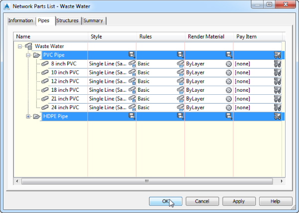
Figure 13.1 A waste water parts list
- Manhole structures
- HDPE pipe
- PVC pipe
In the upcoming section, you will explore planning and creating a parts list. You'll start by examining your local requirements, and then you will compare those needs with what is available in the software.
Planning a Typical Pipe Network
Let's look at a typical waste water design. You'll start by going through the waste water specifications for the jurisdiction in which you're working. The following is an example of a completed checklist for the example's jurisdiction, Sample County:
Waste water network in Sample County
- Recommended structures: Standard concentric manhole, small-diameter cleanout.
- Structure behavior: All structures have 1.5′ (0.46 m) sump, rims, and a 0.10′ (0.03 m) invert drop across all structures. All structures' rim elevations are designed at finished road grade.
-
Structure symbology: Manholes are shown in plan view as a circle with an S inside. Cleanouts are shown as a hatched circle (see Figure 13.2).
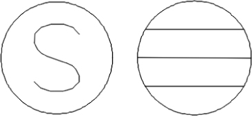
Figure 13.2 Waste water manhole in plan view (left) and a cleanout in plan view (right)
- Manholes are shown in profile view with a coned top and rectangular bottom. Cleanouts are shown as a rectangle (see Figure 13.3).
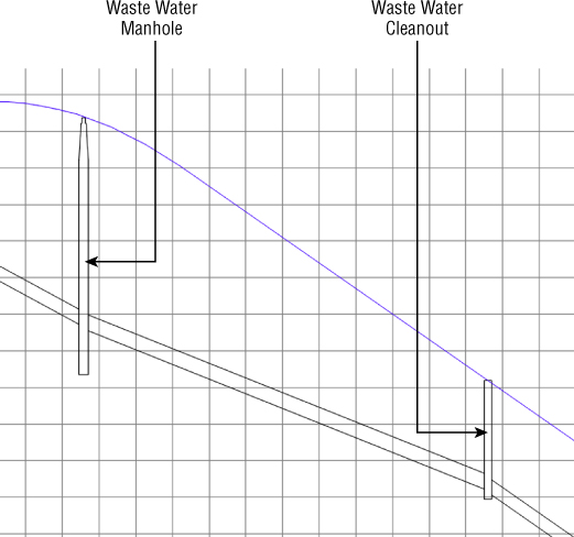
Figure 13.3 Profile view of a waste water manhole (left) and a cleanout (right)
- Recommended pipes: 8″ (200 mm), 10″ (250 mm), and 12″ (300 mm) PVC pipe, per manufacturer specifications.
- Pipe behavior: Pipes must have a minimum cover of 4′ (1.22 m) to the top of the pipe; the maximum slope for all pipes is 10 percent, although minimum slopes may be adjusted to optimize velocity as follows:
Pipe size Minimum slope 8″ (200 mm) 0.40% 10″ (250 mm) 0.28% 12″ (300 mm) 0.22% - Pipe symbology: In plan view, pipes are shown with a CENTER2 linetype line that has a thickness corresponding to the inner diameter of the pipe. In profile view, pipes show both inner and outer walls, with a hatch between the walls to highlight the wall thickness (see Figure 13.4).
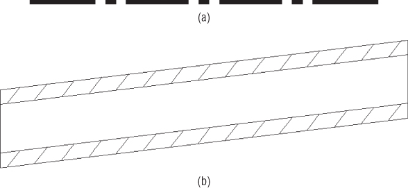
Figure 13.4 Waste water pipe in plan view (a) and in profile view (b)
Now that you know your requirements for Sample County, the next step is to begin entering this information into your Civil 3D template file.
Using Part Rules
Rules define the constraints on things like minimum slope, sump depths, and pipe-invert drops across structure. Rules are assigned to parts in the parts list. Depending on the type of network and the complexity of your design, you may have many rules. Civil 3D allows you to establish structure and pipe rules that will assist in respecting these constraints during initial layout and edits.
Rules don't restrict you from drawing the location and lengths you want. As you draw your pipe network in plan view, Civil 3D tries to adhere to as many rules as it can. If the constraints defined in the rules conflict with each other (for example, maximum slope may be violated to maintain minimum depth), rules are violated even in the layout stage.
Furthermore, rules will never change your design without your direct guidance. For example, if the surface tied to a structure changes, the rim elevation will change, but the pipe invert elevations will not change.
To see where the design needs to be altered, you will need to view the violations in the Status column of Panorama. Panorama is the only place where rule violations are flagged; there is no graphic representation of rule violations in plan view.
Structures and pipes have separate rule sets. When creating rules, don't be thrown off by the fact that the category always reads Storm Sewer, as you'll see in Figure 13.6. You can use these rules regardless of the type of parts list you are creating. You can then add these rule sets to specific parts in your parts list, which you'll build later in this chapter.
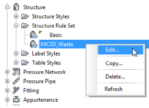
Figure 13.5 On the Settings tab of Toolspace, right-click a structure rule set to edit it.
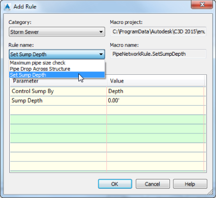
Figure 13.6 In the Add Rule dialog, the category always shows Storm Sewer, but you can use rules for whatever type you want.
Understanding Structure Rules
Structure rule sets are located on the Settings tab of Toolspace, under the Structure branch, as shown in Figure 13.5.
Right-click the rule set and choose Edit. In the Rules tab, click the Add Rule button on the Rules tab in the Structure Rule Set dialog. The Add Rule dialog will appear, which will allow you to access all the various structure rules (see Figure 13.6). Although it looks like you can, you won't be able to change the values until you finalize adding the rule. The rules that are available for the structures are different from the ones that are available for and apply to pipes.
You will have a chance to work with this firsthand in the upcoming exercise.
Maximum Pipe Size Check Rule
The Maximum Pipe Size Check rule (see Figure 13.7) examines all pipes connected to a structure and flags a violation in Prospector if any pipe is larger than your rule. This is a violation-only rule—it won't change your pipe size automatically.
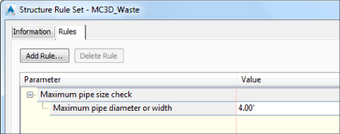
Figure 13.7 The Maximum Pipe Size Check rule option
Pipe Drop Across Structure Rule
The Pipe Drop Across Structure rule (see Figure 13.8) tells any connected pipes how their inverts (or alternatively, their crowns or centerlines) must relate to one another.
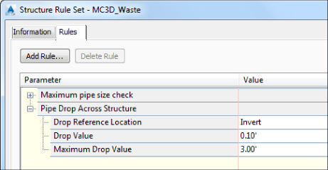
Figure 13.8 The Pipe Drop Across Structure rule options
When a new pipe is connected to a structure that has the Pipe Drop Across Structure rule applied, the following checks take place:
- A pipe drawn to be exiting a structure has an invert equal to or lower than the lowest pipe entering the structure based on the minimum drop across structure setting.
- A pipe drawn to be entering a structure has an invert equal to or higher than the highest pipe exiting the structure based on the minimum drop across structure setting.
- Minimum specified drop distance is calculated by measuring between the lowest entering pipe and the highest exiting pipe. If at any time this value is lower or higher than the rule setting, it will be flagged in the Status column of the Panorama view, as noted previously.
In the hypothetical waste water example, you're required to maintain a 0.10′ (3 cm) invert drop across all structures. You'll use this rule in your structure rule set in the next exercise.
Set Sump Depth Rule
Sump depth is additional structure depth below the lowest pipe invert. The Set Sump Depth rule (Figure 13.9) establishes sump depth for structures.
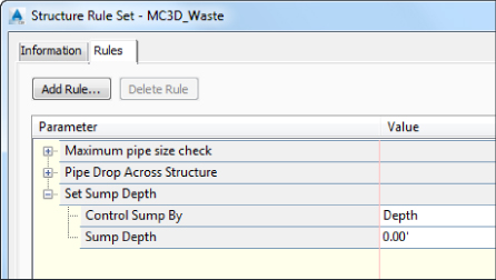
Figure 13.9 The Set Sump Depth rule option
It's important to add a sump depth rule to all of your structure rule sets. If no sump rule is used, Civil 3D will assume a 2′ sump for English units and 2 meters in metric units! If you forget to set this before placing structures, you will need to edit the individual structure properties or make the rule and retroactively apply it to the network.
In the hypothetical waste water example, all the structures have a 1.5′ (0.5 m) sump depth. You'll use this rule in your structure rule set in the next exercise.
Understanding Pipe Rules
Pipe rule sets are located on the Settings tab of Toolspace, under the Pipe branch. After you right-click a pipe rule set and choose Edit (as shown in Figure 13.10), you can access all the pipe rules by clicking the Add Rule button on the Rules tab of the Pipe Rule Set dialog.
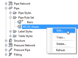
Figure 13.10 Accessing the pipe rules dialog from the Settings tab
Cover And Slope Rule
The Cover And Slope rule (Figure 13.11) allows you to specify your desired slope range and cover range. As you place your pipe network, Civil 3D tries to use the minimum and maximum depths and minimum and maximum slopes to set the initial pipe depth and slope.
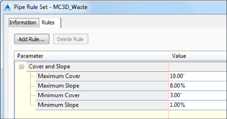
Figure 13.11 The Cover And Slope rule options
Depending on your site conditions, applying this rule to every pipe may not be feasible. In this situation, the rule becomes what is referred to as violation only. You will still be able to place pipes that violate the rule, and the rule will cause a violation message to show in the Status column of the Pipe Network panel of Panorama.
If part of your design changes and you'd like Civil 3D to make another attempt to enforce the Cover And Slope rule, you can use the Apply Rules feature, which is discussed later in this chapter.
Cover Only Rule
The Cover Only rule (Figure 13.12) is designed for use with pipe systems where slope can vary or isn't a critical factor. Like Cover And Slope, this rule is used on first placement. Manual edits can cause rules to be violated. The rule will show as a violation in the Status column of the Pipe Network panel, but no changes to your design take place until you use the Apply Rules command.
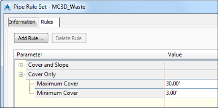
Figure 13.12 The Cover Only rule options
Length Check Rule
Length Check is a violation-only rule; it won't change your pipe length size automatically. The Length Check options (see Figure 13.13) allow you to specify minimum and maximum pipe lengths.
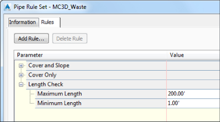
Figure 13.13 The Length Check rule options
Pipe To Pipe Match Rule
The Pipe To Pipe Match rule (Figure 13.14) is also designed for use where there are no true structures (only null structures), including situations where pipe is placed to break into an existing pipe. This rule determines how pipe inverts are assigned when two pipes come together, similar to the Pipe Drop Across Structure rule.
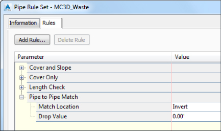
Figure 13.14 The Pipe To Pipe Match rule options
Set Pipe End Location Rule
Without the Set Pipe End Location rule (Figure 13.15), Civil 3D assumes you are measuring pipes from center of structure to center of structure. With the rule in place, you have the capability to determine where the pipe end is located on the structure. The options are Structure Center (the default without the rule), Structure Inner Wall, or Structure Outer Wall.
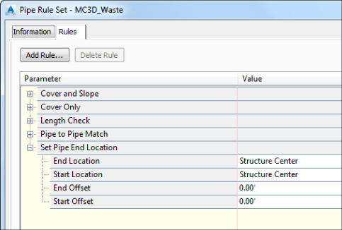
Figure 13.15 The Set Pipe End Location rule options
End Offset and Start Offset are used if you would like to have your pipes protrude past the inner or outer wall on the respective ends. The offset is ignored if the location for the end is set to the center of the structure. The value must be positive and will be ignored if the additional length causes the pipe end to be located past the center of the structure.
Graphically, you probably won't be able to tell that this setting is active until you add labels. The Set Pipe End Location will make a difference in the length and slope labels on pipes.
Creating Structure and Pipe Rule Sets
In this exercise, you'll create one structure rule set and three pipe rule sets for a hypothetical waste water project:
- Open the
1301_RulesTemplate.dwg(1301_RulesTemplate_METRIC.dwg) drawing, which you can download from this book's web page at www.sybex.com/go/masteringcivil3d2015. - On the Settings tab of Toolspace, expand the Structure branch, right-click Structure Rule Set, and click New.
- Switch to the Information tab and enter Waste Water in the Name text box.
- Switch to the Rules tab, and click the Add Rule button.
- In the Add Rule dialog, choose Pipe Drop Across Structure in the Rule Name drop-down. Click OK.
- Expand the new rule and confirm that the parameters in the Structure Rule Set dialog are the following:
Drop Reference Location Invert Drop Value 0.1′ (0.03 m) Maximum Drop Value 3′ (1 m) These parameters establish a rule that will match your hypothetical municipality's standard for the drop across waste water structures.
- Click the Add Rule button again.
- In the Add Rule dialog, choose Set Sump Depth in the Rule Name drop-down. Click OK.
- Expand the new rule. Change the Sump Depth parameter to 1.5’ (0.5 m) in the Structure Rule Set dialog to meet the hypothetical municipality's standard for sump in waste water structures, and click OK.
- On the Settings tab of Toolspace, expand the Pipe branch, right-click the pipe rule set, and choose New.
- Switch to the Information tab and enter 8 Inch Waste Water Pipe (for metric, 200 mm Waste Water Pipe) for the name.
- Switch to the Rules tab. Click Add Rule.
- In the Add Rule dialog, choose Cover And Slope in the Rule Name drop-down. Click OK.
- Expand the Cover And Slope rule and then modify the parameters to match the constraints established by your hypothetical municipality for 8″ (200 mm) pipe, as follows:
Maximum Cover 10′ (3 m) Maximum Slope 10% Minimum Cover 4′ (1.5 m) Minimum Slope 0.40% - Click OK.
- In the Settings tab of Toolspace, expand Pipe Rule Set and select the rule set you just created. Right-click, and choose Copy.
- Switch to the Information tab and enter 10 Inch Waste Water Pipe (for metric, 250 mm Waste Water Pipe) in the Name text box.
- Switch to the Rules tab, expand the Cover And Slope rule, and then modify the parameters to match the constraints established by your hypothetical municipality for a 10″ (250 mm) pipe, as follows.
Maximum Cover 10′ (3 m) Maximum Slope 10% Minimum Cover 4′ (1.5 m) Minimum Slope 0.28% - Click OK when you have finished modifying the rule set. Repeat the process to create a rule set for the 12″ (300 mm) pipe using the following parameters:
Maximum Cover 10′ (3 m) Maximum Slope 10% Minimum Cover 4′ (1.5 m) Minimum Slope 0.22% - You should now have one structure rule set and three pipe rule sets.
- Save and close your drawing.
For your reference, completed versions of the drawing (1301_RulesTemplate_FINISHED.dwg and 1301_RulesTemplate_METRIC_FINISHED.dwg) are available with the rest of this book's download.
Putting Your Parts List Together
Everything you've done in this chapter up to this point is leading up to the creation of the parts list. Your parts lists should reside in your Civil 3D template file. Having this information in your template will prevent you from needing to re-create the parts list for every project. You will have multiple parts lists for each type of system you are creating and possibly for each jurisdiction you work in. You might even consider setting up a template for each jurisdiction.
- Open the
1302_PartsListTemplate.dwg(1302_PartsListTemplate_METRIC.dwg) drawing. - From the Settings tab, expand the Pipe Network branch, and expand Parts Lists.
In the drawing, there are currently two parts lists: Standard and Storm Sewer.
- Right-click Parts Lists and select Create Parts List.
- In the Network Parts List dialog, switch to the Information tab and name the parts list Sample County Waste Water.
- Switch to the Pipes tab.
- Right-click New Parts List and select Add Part Family, as shown in Figure 13.16.
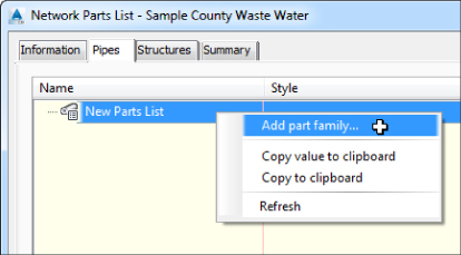
Figure 13.16 Add a part family for your new parts list.
The Part Catalog dialog will appear.
- As shown in Figure 13.17, place a check mark next to PVC Pipe (PVC Pipe SI in the metric catalog) and click OK.
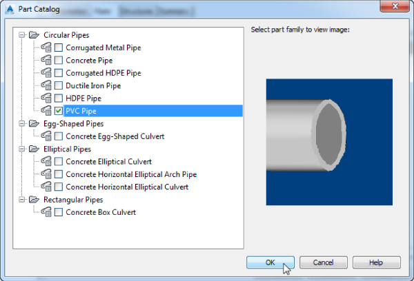
Figure 13.17 Choosing a part family to add
At this step, the parts list name should appear at the top of the pipe list.
- Expand the pipe list name to see the new PVC Pipe family you just added.
- Right-click PVC Pipe (PVC Pipe SI for metric users) and select Add Part Size, as shown in Figure 13.18.
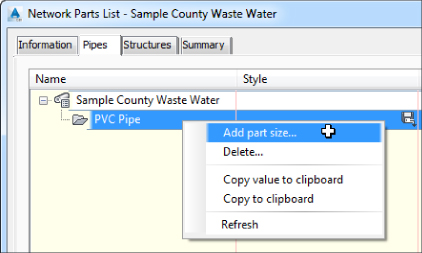
Figure 13.18 Add a new part size to the PVC Pipe part family.
- In the Part Size Creator dialog, click the drop-down in the Inner Pipe Diameter field, as highlighted in Figure 13.19.
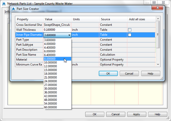
Figure 13.19 Set the diameter and material for all the needed pipes.
- Select 8 Inch (metric: 200 mm). Click OK.
- Expand the new PVC Pipe category to examine the result. Repeat steps 9 through 11 for 10″ (250 mm) and 12″ (300 mm) pipes.
In this example, the pipes will share the same style. Using the disk icon in the PVC Pipe part family row of the table, you will apply your style choice to the entire PVC family.
For the columns Render Material and Pay Item, leave the defaults. Render materials and pay items do not affect the design portion of the pipe network. Render materials are used if you want to give a realistic material to the object for visualization purposes. You will take an in-depth look at assigning pay items to a parts list in Chapter 17, “Quantity Takeoff.”
 In the PVC Pipe part family row, click the disk icon in the Style column.
- Set Pipe Style to Single Line (Waste Water) and click OK.
 For each pipe size, click the Pipe Rule Set icon in the Rules column, choose the respective rule in the Pipe Rule Set dialog, and then click OK.
At the end of the process, your Pipes tab will look like Figure 13.20.
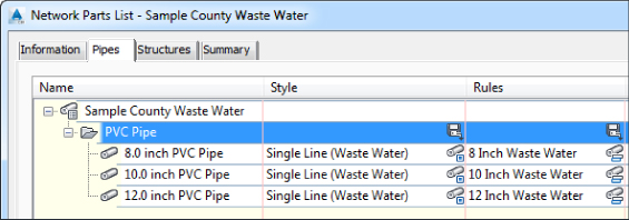
Figure 13.20 The completed Pipes tab
- Switch to the Structures tab and expand New Parts List.
Notice there is already a null structure in the listing.
 Expand the Null Structure part family and click the Structure Style icon for the null structure.
- Change the Null Structure style to Null and click OK.
- Right-click the main heading New Parts List and select Add Part Family.
- In the Part Catalog dialog, locate the Junction Structures With Frames grouping and place a check mark next to Concentric Cylindrical Structure and Cylindrical Structure Slab Top Circular Frame (in the metric drawings, the structure descriptions end with SI), as shown in Figure 13.21. Click OK.
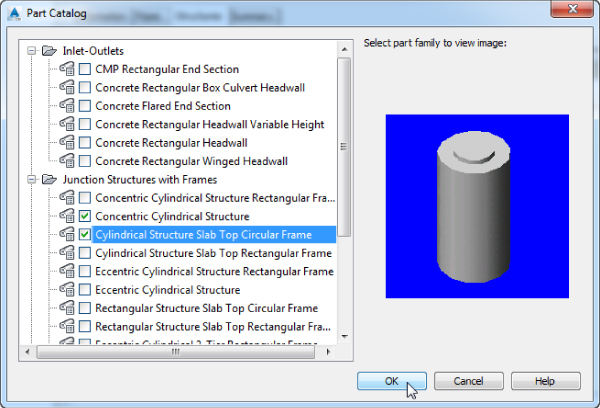
Figure 13.21 Adding structure part families
- Right-click Concentric Cylindrical Structure and select Add Part Size.
- In the Part Size Creator dialog, select an Inner Structure Diameter of 48″ (1,200 mm).
- Leave all other size options at their defaults, and click OK.
- Repeat steps 22 through 24 to add the 60″ (1,500 mm) structure.
If the Add Part Size option is not available in the list, make sure you don't have multiple parts selected. In this case, just select another part family and switch back to the desired part family you need to add new part sizes.
- Use the disk icon to set the style for both concentric cylindrical structures to Waste Water Manhole.
- Right-click Cylindrical Structure Slab Top Circular Frame, and select Add Part Size.
- Set Inner Structure Diameter to 15″ (450 mm), and click OK.
- Using the same process you used in step 25, set Structure Style to Cleanout.
- Use a similar procedure to set the rules for the three new structures to Waste Water.
If you expand all the structure part families, your network parts list will look like Figure 13.22.
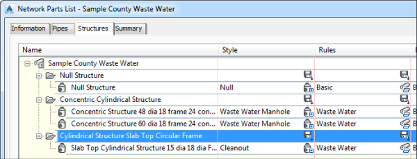
Figure 13.22 The completed Structures tab in your new parts list
- Click OK to close the network parts list.
- Save and close the drawing.
For your reference, completed versions of the drawing (1302_PartsListTemplate_FINISHED.dwg and 1302_PartsListTemplate_METRIC_FINISHED.dwg) are available with the rest of this book's download.
Creating a Waste Water Network
Earlier, you prepared a parts list for a typical waste water network. This chapter will lead you through several methods for using that parts list to design, edit, and annotate a pipe network.
A pipe network, such as the one in Figure 13.23, can have many branches. In most cases, the pipes and structures in your network will be connected to each other; however, they don't necessarily have to be physically touching to be included in the same pipe network.
Figure 13.23 A typical Civil 3D pipe network
There are several ways to create pipe networks. You can do so using the Civil 3D pipe layout tools. You can also create pipe networks from certain AutoCAD and Civil 3D objects, such as lines, polylines, alignments, and feature lines.
Establishing Pipe Network Parameters
This section will give you an overview of establishing pipe network parameters. Use this section as a reference for the exercises in this chapter. When you're ready to create a pipe network by layout, select the Home tab ![]() Create Design panel and choose Pipe Network
Create Design panel and choose Pipe Network ![]() Pipe Network Creation Tools. The Create Pipe Network dialog appears (see Figure 13.24), and you can establish your settings.
Pipe Network Creation Tools. The Create Pipe Network dialog appears (see Figure 13.24), and you can establish your settings.
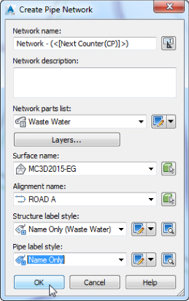
Figure 13.24 The Create Pipe Network dialog
Before you can create a pipe network, you must give your network a name, but more important, you need to assign a parts list for your network. As you saw earlier, the parts list provides a toolkit of pipes, structures, rules, and styles to automate the pipe network design process. It's also important to select a reference surface in this interface. This surface will be used for rim elevations and rule application.
When creating a pipe network, you'll be prompted for the following options:
- Network Name Choose a name for your network that is meaningful and will help you identify it in Prospector and other locations.
- Network Description The description of your pipe network is optional. You might make a note of the date, the type of network, and any special characteristics.
- Network Parts List Choose the parts list that contains the parts, rules, and styles you want to use for this design.
- Surface Name Choose the surface that will provide a basis for applying cover rules as well as provide an insertion elevation for your structures (in other words, rim elevations). You can change this surface later or for individual structures. For proposed pipe networks, this surface is usually a finished ground surface or a composite surface of the existing and proposed surfaces, which can be set to No Display in the drawing.
- Alignment Name Choose an alignment that will provide station and offset information for your structures in Prospector as well as any labels that call for alignment stations and/or offset information. Because most pipe networks have several branches, it may not be meaningful for every structure in your network to reference the same alignment. Therefore, you may find it better to leave your Alignment option set to None in this dialog and set it for individual structures later using the layout tools or Structure list in Prospector.
- Structure Label Style and Pipe Label Style As you create the network, you'll have the option to add labels as you go. If you choose to use a label style that displays text (i.e., not the <None> option), these labels will apply only to the plan view. Section and profile pipe network labels are added in a separate area. You will learn about adding labels later in this chapter. For more information about creating label styles, see Chapter 18, “Label Styles.”
Using the Network Layout Creation Tools
Creating a pipe network with layout tools is much like creating other Civil 3D objects. After naming and establishing the parameters for your pipe network, you'll be presented with a special toolbar that you can use to lay out pipes and structures in plan, which will also drive a vertical design.
![]() After establishing your pipe network parameters in the Create Pipe Network dialog (shown earlier in Figure 13.24), click OK; the Network Layout Tools toolbar will appear (see Figure 13.25).
After establishing your pipe network parameters in the Create Pipe Network dialog (shown earlier in Figure 13.24), click OK; the Network Layout Tools toolbar will appear (see Figure 13.25).
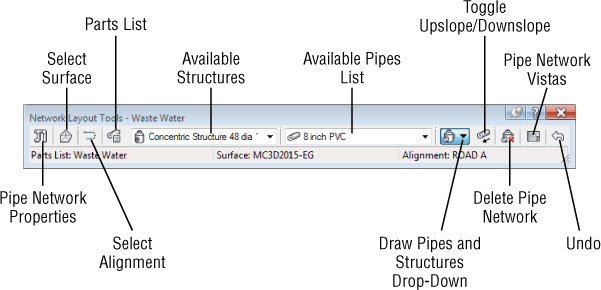
Figure 13.25 The Network Layout Tools toolbar
![]() Clicking the Pipe Network Properties tool displays the Pipe Network Properties dialog, which contains the settings for the entire network. If you mistyped any of the parameters in the original Create Pipe Network dialog, you can change them here. In addition, you can set the default label styles for the pipes and structures in this pipe network.
Clicking the Pipe Network Properties tool displays the Pipe Network Properties dialog, which contains the settings for the entire network. If you mistyped any of the parameters in the original Create Pipe Network dialog, you can change them here. In addition, you can set the default label styles for the pipes and structures in this pipe network.
The Pipe Network Properties dialog contains the following tabs:
- Information On this tab, you can rename your network, provide a description, and choose whether you'd like to see network-specific tooltips.
- Layout Settings Here you can change the default label styles, network parts list, reference surface and alignment, master object layers for plan pipes and structures, as well as name templates for your pipes and structures (see Figure 13.26).
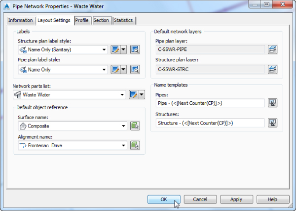
Figure 13.26 The Layout Settings tab of the Pipe Network Properties dialog
- Profile On this tab, you can change the default profile label styles and master object layers for profile pipes and structures (see Figure 13.27).
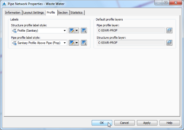
Figure 13.27 The Profile tab of the Pipe Network Properties dialog
- Section Here you can change the master object layers for network parts in a section (see Figure 13.28).
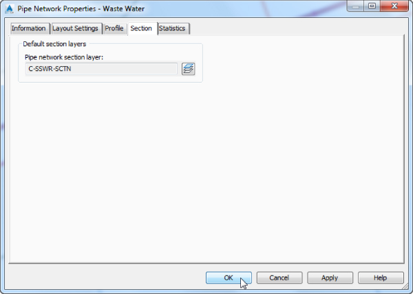
Figure 13.28 The Section tab of the Pipe Network Properties dialog
- Statistics This tab gives you a snapshot of your pipe network information, such as minimum and maximum elevation information, pipe and structure quantities, and the assigned reference objects to the network such as alignments and surfaces (see Figure 13.29).
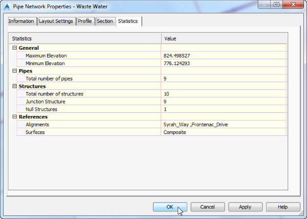
Figure 13.29 The Statistics tab of the Pipe Network Properties dialog
![]() The Select Surface tool on the Network Layout Tools toolbar allows you to switch between reference surfaces while you're placing network parts if needed. However, you should create a merged surface containing your existing surface plus your final design. Whenever possible, you should use a surface that incorporates the entire site (e.g., existing and proposed pasted together) to avoid needing to switch between surfaces.
The Select Surface tool on the Network Layout Tools toolbar allows you to switch between reference surfaces while you're placing network parts if needed. However, you should create a merged surface containing your existing surface plus your final design. Whenever possible, you should use a surface that incorporates the entire site (e.g., existing and proposed pasted together) to avoid needing to switch between surfaces.
![]() The Select Alignment tool on the Network Layout Tools toolbar lets you switch between : reference alignments while you're placing network parts, similar to the Select Surface tool.
The Select Alignment tool on the Network Layout Tools toolbar lets you switch between : reference alignments while you're placing network parts, similar to the Select Surface tool.
![]() The Parts List tool allows you to switch parts lists for the pipe network.
The Parts List tool allows you to switch parts lists for the pipe network.
The Structure drop-down (the image on the left in Figure 13.30) lets you choose which structure you'd like to place next, and the Pipes drop-down (the image on the right in Figure 13.30) allows you to choose which pipe you'd like to place next. Your choices come from the active : network parts list.
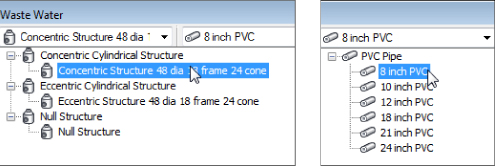
Figure 13.30 The Structure drop-down (left) and the Pipes drop-down (right)
The options for the Draw Pipes And Structures category let you choose what type of parts you'd like to lay out next. You can choose Pipes And Structures, Pipes Only, or Structures Only.
Placing Parts in a Network
Network Parts can be placed in a manner similar to those of other Civil 3D objects or AutoCAD objects such as polylines. You can use your mouse, transparent commands, dynamic input, object snaps, and other drawing methods when laying out your pipe network.
If you choose Pipes And Structures, a structure is placed wherever you click, and the structures are joined by pipes. If you choose Pipes Only, you can connect previously placed structures. If you have Pipes Only selected and there is no structure where you click, a null structure is placed to connect your pipes.
![]() Use the Structures Only option when you want to add a structure along an existing pipe run. Watch for the “boxing glove” glyph to appear, indicating that the pipe network recognizes the connection. Clicking to connect to the pipe breaks the pipe into two pieces and places a structure (or null structure) at the break point.
Use the Structures Only option when you want to add a structure along an existing pipe run. Watch for the “boxing glove” glyph to appear, indicating that the pipe network recognizes the connection. Clicking to connect to the pipe breaks the pipe into two pieces and places a structure (or null structure) at the break point.
![]() While you're actively placing pipes and structures, you may want to connect to a previously placed part. For example, there may be a service or branch that connects into a structure along the main trunk. Begin placing the new branch. When you're ready to tie into a structure, you'll get a circular connection marker as your cursor comes within connecting distance of that structure. If you click to place your pipe when this marker is visible, a structure-to-pipe connection will form and the end of the pipe will automatically be set as the center or attachment point for the structure. If you add a structure to the end of a pipe, the connection marker will be a box marker instead of a circular marker.
While you're actively placing pipes and structures, you may want to connect to a previously placed part. For example, there may be a service or branch that connects into a structure along the main trunk. Begin placing the new branch. When you're ready to tie into a structure, you'll get a circular connection marker as your cursor comes within connecting distance of that structure. If you click to place your pipe when this marker is visible, a structure-to-pipe connection will form and the end of the pipe will automatically be set as the center or attachment point for the structure. If you add a structure to the end of a pipe, the connection marker will be a box marker instead of a circular marker.
![]() As you create pipes, the default behavior is to draw them upstream to downstream. The Toggle Upslope/Downslope tool changes the flow direction of your pipes as they're placed. In Figure 13.31, structure 9 was placed before structure 10.
As you create pipes, the default behavior is to draw them upstream to downstream. The Toggle Upslope/Downslope tool changes the flow direction of your pipes as they're placed. In Figure 13.31, structure 9 was placed before structure 10.
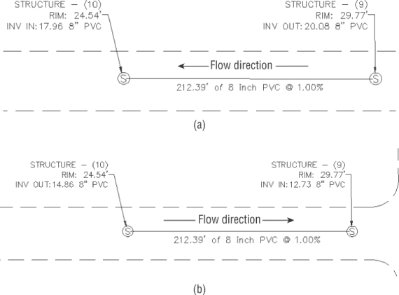
Figure 13.31 Using the Downslope toggle (a) and the Upslope toggle (b) to create a pipe network leg
![]() Click Delete Pipe Network Object to delete pipes or structures of your choice. AutoCAD Erase can also delete network objects, but be careful that you don't accidentally remove more objects than you intend. Also the AutoCAD Erase command might cause corruption when used to erase pipe networks parts; therefore, it isn't a recommended method. Always try to use the Delete tool available under the Network Layout Tools toolbar, or delete objects using either Pipe Network Vistas or through the Pipe Network branch of Toolspace, Prospector tab.
Click Delete Pipe Network Object to delete pipes or structures of your choice. AutoCAD Erase can also delete network objects, but be careful that you don't accidentally remove more objects than you intend. Also the AutoCAD Erase command might cause corruption when used to erase pipe networks parts; therefore, it isn't a recommended method. Always try to use the Delete tool available under the Network Layout Tools toolbar, or delete objects using either Pipe Network Vistas or through the Pipe Network branch of Toolspace, Prospector tab.
![]() Clicking Pipe Network Vistas brings up the Pipes and Structures tabs in Panorama (see Figure 13.32), where you can make tabular edits to your pipe network while the Network Layout Tools toolbar is active.
Clicking Pipe Network Vistas brings up the Pipes and Structures tabs in Panorama (see Figure 13.32), where you can make tabular edits to your pipe network while the Network Layout Tools toolbar is active.
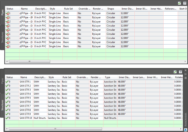
Figure 13.32 Pipe Network Vistas via Panorama for pipes (top) and structures (bottom)
The Pipe Network Vistas interface is similar to what you encounter in the Pipe Networks branch of Toolspace, Prospector tab. The advantage of using Pipe Network Vistas is that you can make tabular edits without leaving the Network Layout Tools toolbar. You can edit pipe properties, such as Invert and Slope, on the Pipes tab, and you can edit structure properties, such as Rim and Sump, on the Structures tab.
Creating a Waste Water Network
This exercise will apply the concepts taught in this section and give you hands-on experience using the Network Layout Tools toolbar:
- Open
1303_Pipes.dwg(1303_Pipes_METRIC.dwg), which you can download from this book's web page. - Expand the Surfaces branch in Prospector.
This drawing has several surfaces that have a _No Display style applied to simplify the drawing. The surface you will be working from is a composite of the existing conditions, corridor surfaces, and grading surfaces.
- Expand the Alignments and Centerline Alignments branches, and notice that there are several road alignments (no action is required).
 On the Home tab
  Create Design panel Pipe Network drop-down, select Pipe Network Creation Tools.
- In the Create Pipe Network dialog (shown previously in Figure 13.24), give your network the following information:
- Network Name: Waste Water Network
- Network Parts List: Waste Water
- Surface Name: Composite
- Alignment Name: Syrah Way
- Structure Label Style: Data With Connected Pipes (Waste Water)
- Pipe Label Style: Length Description And Slope
- Click OK.
The Network Layout Tools toolbar will appear.
- From the structure list, expand the Concentric Cylindrical Structure branch, choose Concentric Structure 48 Dia 18 Frame 24 Cone (metric: Concentric Structure 1,200 Dia 450 Frame 600 Cone).
- From the pipe list, expand the PVC pipe branch and choose 8 Inch PVC (200 mm PVC).
 Click the Draw Pipes And Structures tool. Working right to left, snap using an Intersection Osnap to the X labeled 1 in the drawing to place the first structure. Snap the X labeled 2 to place the second structure.
- Without exiting the command, go back to the Network Layout Tools toolbar and change the Pipe drop-down from 8 Inch PVC to 10 Inch PVC (200 mm PVC to 250 mm PVC) and then place structures at the Xs labeled 3, 4, and 5.
The labels show that the diameter of the pipe between these structures is 10″ (250 mm).
- Press ↵ to exit the command.
Next, you'll add a branch of the network from ROAD B. You may want to use the label grip to drag the label off to the side. This will form the leaders as shown in Figure 13.33, making the next step easier.
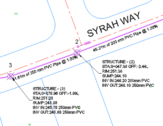
Figure 13.33 The connection marker appears when your cursor is near the existing structure.
- Go back to the Network Layout Tools toolbar, and select 8 Inch PVC (200 mm PVC) from the pipe list.
- Click the Draw Pipes And Structures tool button again.
- Working north to south, click to place the next structure at the X labeled 6.
- Tie into the ROAD A branch by moving your cursor near structure 2. You will be ready to click when you see the “sunshine” glyph, indicating that the pipe will tie into the structure.
- Press ↵ to exit the command.
Observe your pipe network, including the labeling that automatically appeared as you drew the network.
- Expand the Pipe Networks branch in Prospector in Toolspace, and locate your Waste Water Network.
- Expand Waste Water Network, and click the Pipes branch.
The list of pipes appears in the preview pane.
- Click the Structures branch; the list of structures appears in the preview pane.
- Close the Network Layout Tools toolbar, and save the drawing.
For your reference, completed versions of the drawing (1303_Pipes_FINISHED.dwg and 1303_Pipes_METRIC_FINISHED.dwg) are available with the rest of this book's download.
Creating a Storm Drainage Pipe Network from a Feature Line
![]() If you already have an object in your drawing that represents a pipe network (such as a polyline, an alignment, or a feature line), you can take advantage of the Create Pipe Network From Object command in the Pipe Network drop-down.
If you already have an object in your drawing that represents a pipe network (such as a polyline, an alignment, or a feature line), you can take advantage of the Create Pipe Network From Object command in the Pipe Network drop-down.
This option can be used for applications such as converting surveyed pipe runs into pipe networks and bringing forward legacy drawings that used AutoCAD linework to represent pipes. The Create Pipe Network From Object option creates a pipe for every linear segment of your object and places a structure at every vertex of your object. Each object you convert will initially go to a separate network. However, once you have several networks, you can easily merge them if needed.
This exercise will give you hands-on experience building a pipe network from a feature line with elevations and merging it with an existing network:
- Open the
1304_PipesFromObject.dwg(1304_PipesFromObject_METRIC.dwg) file.This drawing contains the feature line you will use to generate a storm network.
- Expand the Surfaces branch in Prospector.
This drawing has several surfaces that have a _No Display style applied to simplify the drawing (no action is required).
- Expand the Alignments and Centerline Alignments branches, and notice that there are several road alignments.
In the drawing, a cyan feature line runs through Syrah Way (the horizontal road) and then goes onto Frontenac Drive. This feature line represents utility information for a storm-drainage line. The elevations of this feature line correspond with invert elevations that you'll apply to your pipe network.
 Choose Create Pipe Network From Object from the Home tab, Create Design panel, Pipe Network drop-down.
- At the
Select Object or [Xref]:prompt, select the cyan feature line near the eastern side of the line.You'll see a preview (see Figure 13.34) of the pipe-flow direction that is based on where you selected the line. In this case, the east end of the feature line is considered the upstream end.
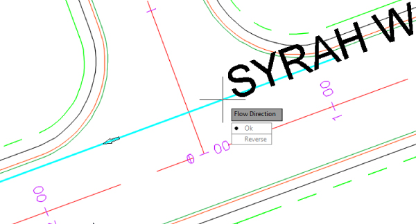
Figure 13.34 The flow-direction preview
- At the
Flow Direction [OK Reverse] <Ok>:prompt, press ↵ to choose OK.The Create Pipe Network From Object dialog appears, as shown in Figure 13.35.
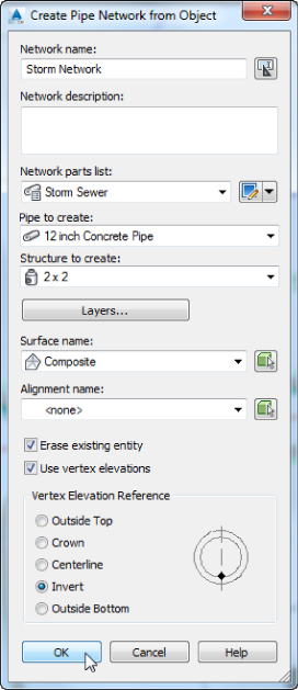
Figure 13.35 Converting a feature line to a pipe network
- In the dialog, give your pipe network the following information:
- Network Name: Storm Network
- Network Parts List: Storm Sewer
- Pipe To Create: 12 Inch Concrete Pipe (300 mm Concrete Pipe)
- Structure To Create: From the Rectangular Junction Structure NF (SI for metric) collection 2 × 2 (750 × 750 mm Rectangular Structure)
- Surface Name: Composite
- Alignment Name: <none>
- Erase Existing Entity check box: Selected
- Use Vertex Elevations check box: Selected
- Vertex Elevation Reference: Invert
If you select Use Vertex Elevations, the pipe rules for your chosen parts list will be ignored. If it becomes necessary later, you can use the Apply Rules tool as discussed in the next section of this chapter.
- Click OK. A pipe network will be created.
Next, you will merge this network with another network that exists in the drawing.
- Select a pipe or structure from the newly created network. From the Pipe Networks contextual tab Modify panel, select Merge Networks.
- In the Select Pipe Network To Be Merged Into Another Network dialog, highlight Storm Network and click OK.
- In the Select Destination Pipe Network dialog, highlight Existing Storm Network and click OK.
- Save and close the drawing.
This exercise combined all your object-created networks into a more manageable single network.
For your reference, completed versions of the drawing (1304_PipesFromObject_FINISHED.dwg and 1304_PipesFromObject_METRIC_FINISHED.dwg) are available with the rest of this book's download.
Editing a Pipe Network
You can edit pipe networks in several ways:
- Using drawing layout edits such as grip, move, and rotate
- Grip-editing the pipe size
- Using vertical movement edits using grips in profile (see the “Editing Pipe Networks in Profile View Using Grips” section later in this chapter)
 Using tabular edits in the Pipe Networks branch in Prospector or from Pipe Network Vistas (via Panorama) from the Network Layout Tools toolbar
- Right-clicking a network part to access tools such as Swap Part or Pipe/Structure Properties
- Returning to the Network Layout Tools toolbar by right-clicking the object and choosing Edit Network
- Selecting the pipe network in Toolspace Prospector, right-clicking, and choosing Edit Network
- Selecting a network part to access the Pipe Networks contextual tab
You will have the chance to explore most of these methods in the following sections.
Changing Flow Direction
By default, Civil 3D pipes are drawn upstream to downstream. It is easy to forget the Toggle Upslope/Downslope tool located on the Network Layout Tools. If you forget to use it, don't fret; you can change the flow direction after the pipes are placed.
To change flow direction, select any part from a pipe network to open the Pipe Networks contextual tab. Select Change Flow Direction from the drop-down portion of the Modify panel. Change Flow Direction allows you to reverse the pipe's understanding of which direction it flows, which comes into play when you're using the Apply Rules command and when you're annotating flow direction with a pipe label–slope arrow.
Changing the flow direction of a pipe doesn't modify the pipe's inverts in any way. By default, a pipe's flow direction depends on how the pipe was drawn and how the Toggle Upslope/Downslope tool was set when the pipe was drawn:
- If the toggle was set to Downslope (the default setting), the pipe flow direction is set to Start To End, which means the first endpoint you placed is considered the start of flow and the second endpoint is established as the end of flow.
- If the toggle was set to Upslope when the pipe was drawn, the pipe flow direction is set to End To Start, which means the first endpoint placed is considered the end for flow purposes and the second endpoint the start.
After pipes are drawn, by default they will have a Start To End flow direction. This is among the four options of flow that can be assigned by going to Pipe Properties or by going to Prospector ![]() Pipe Networks
Pipe Networks ![]() Network Name
Network Name ![]() Pipe Branch:
Pipe Branch:
- Start To End A pipe label–flow arrow shows the pipe direction from the first pipe endpoint drawn to the second endpoint drawn, regardless of invert or slope.
- End To Start A pipe label–flow arrow shows the pipe direction from the second pipe endpoint drawn to the first pipe endpoint drawn, regardless of invert or slope.
- Bi-Directional Typically, this is a pipe with zero slope that is used to connect two bodies that can drain into each other, such as two stormwater basins, septic tanks, or overflow vessels. The direction arrow is irrelevant in this case.
- By Slope A pipe label–flow arrow shows the pipe direction as a function of pipe slope. For example, if End A has a higher invert than End B, the pipe flows from A to B. If B is edited to have a higher invert than A, the flow direction flips from B to A.
Editing Your Network in Plan View
When selected, a structure has two types of grips, shown in Figure 13.36. The first is a square grip located at the structure insertion point. You can use this grip to grab the structure and stretch/move it to a new location using the insertion point as a base point. Stretching a structure results in the movement of the structure as well as any connected pipes. Moving a structure allows the reposition of the structure to a new place while the connected pipes remain at the original location. You can also scroll through Stretch, Move, and Rotate by using your spacebar once you've grabbed the structure by this grip.
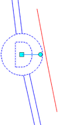
Figure 13.36 Two types of structure grips
The second structure grip is a rotational grip that you can use to spin the structure about its insertion point. This is useful for aligning eccentric structures, such as rectangular junction structures. Note that even though they will be rotated in plan view, the specified rotation may not be properly represented in the profile view.
In plan view, many common AutoCAD Modify commands work with structures. You can execute the following commands normally: Move, Copy, Rotate, Align, and Mirror. (Scale doesn't have an effect on structures.) You can use the AutoCAD Erase command to erase network parts. Note that erasing a network part in plan completely removes that part from the network. Once erased, the part disappears from plan, profile view, Prospector, and so on. Always remember that even though the AutoCAD Erase command is supported, its use is not recommended in the management of network parts.
When selected, a pipe end has two types of grips (see Figure 13.37). The first is a square endpoint-location grip. Using this grip, you can change the location of the pipe end without constraint. You can move it in any direction; make it longer or shorter; and take advantage of Stretch, Move, Rotate, and Scale by using your spacebar.
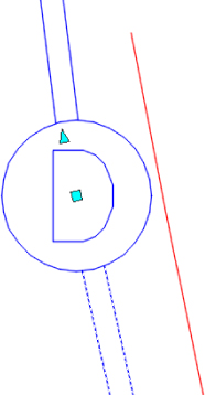
Figure 13.37 Two types of pipe-end grips
The second grip (triangular) is a pipe-length grip. This grip lets you extend a pipe along its current bearing and slope.
A pipe midpoint also has two types of grips (see Figure 13.38). The first is a square location grip that lets you move the pipe using its midpoint as a base point.
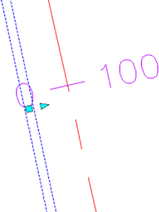
Figure 13.38 Two types of pipe midpoint grips
The second grip is a triangular-shaped pipe-diameter grip. Stretching this grip gives you a tooltip showing allowable diameters for that pipe, which are based on your parts list. Use this grip to make quick visual changes to the pipe diameter.
Using the Pipe Network Vista Effectively
![]() To access the full tabular version of your pipe network, the best place to go is to the Pipe Networks contextual tab
To access the full tabular version of your pipe network, the best place to go is to the Pipe Networks contextual tab ![]() Modify panel
Modify panel ![]() Edit Pipe Network button.
Edit Pipe Network button.
![]() Clicking Edit Pipe Network will display the Network Layout toolbar, from which you can click the Pipe Network Vistas (aka Panorama) tool. This will display the grid view shown in Figure 13.39.
Clicking Edit Pipe Network will display the Network Layout toolbar, from which you can click the Pipe Network Vistas (aka Panorama) tool. This will display the grid view shown in Figure 13.39.
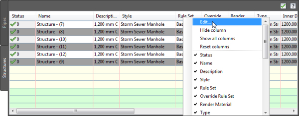
Figure 13.39 Selecting multiple rows and right-clicking the column name allows you to edit multiple items at once.
Note that pipes and structures are listed on separate tabs. Many items can be edited from this view. Subtle shading of the columns indicates which rows can be modified. If a column has a light gray background, this means the value is calculated or for information only.
![]() The Status column indicates any rule violations that exist in the network. When a rule violation exists, a red symbol will appear with the number of violations. When you pause your cursor over one of these symbols, a tooltip will inform you which rule has been violated.
The Status column indicates any rule violations that exist in the network. When a rule violation exists, a red symbol will appear with the number of violations. When you pause your cursor over one of these symbols, a tooltip will inform you which rule has been violated.
You can adjust many things in this interface, but you'll find it cumbersome for some tasks. The interface is best used for the following:
- Batch Changes to Styles, Render Materials, Reference Surfaces, Reference Alignments, Rule Sets, and So On Use your Shift or Ctrl key to select the desired rows, and then right-click the column header of the property you'd like to change. Choose Edit, and then select the new value from the drop-down. If you find yourself doing this on every project for most network parts, confirm that the correct values are set in your parts list and in the Pipe Network Properties dialog.
- Batch Changes to Pipe Description Use your Shift key to select the desired rows, and then right-click the Description column header. Choose Edit, and then enter your new description. If you find yourself doing this on every project for most network parts, check your parts list. If a certain part will always have the same description, you can add it to your parts list and prevent the extra step of changing it here.
- Changing Pipe or Structure Names You can change the name of a network part by typing in the Name field. If you find yourself doing this on every project for every part, check that you're taking advantage of the Name templates in your Pipe Network Properties dialog (which can be further enforced in your Pipe Network command settings).
This interface can be useful for changing pipe inverts, crowns, and centerline information. Keep in mind that Civil 3D will allow you to make changes that violate your pipe rules. Edits to a single pipe or structure are dynamic to parts that are directly connected, but Civil 3D will not reapply the rules for you automatically.
Editing Using the Pipe Networks Contextual Tab
You can perform many edits at the individual part level by selecting it. The Pipe Networks contextual tab will appear for the object you have selected.
If you realize you placed the wrong part at a certain location—for example, if you placed a catch basin where you need a drainage manhole—use the Swap Part option on the Pipe Networks contextual tab (see Figure 13.40). You'll be given a list of all the relevant parts from the parts list associated with the Pipe Network.

Figure 13.40 Selecting a network part brings up the Pipe Networks contextual tab with many options, including Swap Part.
The same properties listed in Prospector (or Pipe Network Vistas) can be accessed on an individual part level by selecting a pipe or structure and choosing Pipe Properties or Structure Properties from the Pipe Networks contextual tab. A dialog like the Structure Properties dialog in Figure 13.41 will open, with several tabs that you can use to edit that particular part.
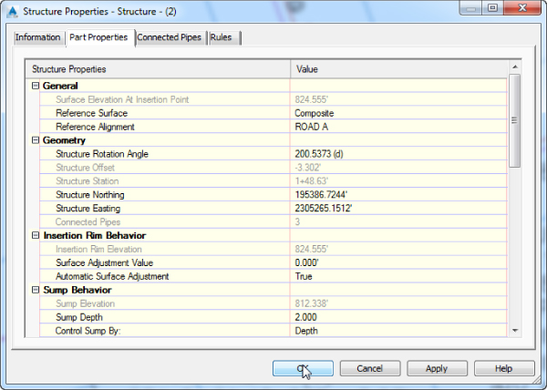
Figure 13.41 The Part Properties tab in the Structure Properties dialog gives you the opportunity to perform many edits and adjustments.
The Labels & Tables Panel
Many objects have a Labels & Tables panel in their contextual tabs. This panel (Figure 13.42) is where you do the most annotation labeling for pipes.
- Add Labels For the best control over what styles are used in your label, use the Add Pipe Network Labels option. From there, you can add labels for the selected pipe network using the sub-options such as Entire Network Plan, Entire Network Profile, Entire Network Section, Single Part Plan, Single Part Profile, Single Part Section, Spanning Pipes Plan, and Spanning Pipes Profile.
- Add Tables You can add a structure or pipe table.
- Reset Labels This Reset Labels is different from the Reset Label option you see when right-clicking directly on a pipe or structure label. By using this specific contextual ribbon command, pipe networks that are in the drawing via data reference will be labeled using styles from the source drawing. For more information on source drawings and data references, see Chapter 16, “Advanced Workflows.”
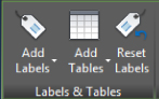
Figure 13.42 The Labels & Tables panel
The General Tools Panel
The General Tools panel (Figure 13.43) is common to all Civil 3D objects' contextual tabs.
- Properties Toggles the Properties palette on and off.
- Object Viewer Allows you to view the selected object or objects in 3D via a separate window.
- Isolate Objects Selected objects will be the only objects visible on the screen. This is useful if you are working in a tight area and do not want to see extraneous objects, and it is much quicker than clicking to turn off or freeze layers.
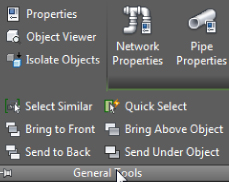
Figure 13.43 The General Tools panel in the Pipe Networks contextual tab
These tools are available via the General Tools panel drop-down.
- Select Similar This is the best tool ever invented! Select an example object or objects, and then click Select Similar. All objects of the same type and layer will be selected. This works great on base AutoCAD objects, not just Civil 3D objects.
- Quick Select or QSelect Opens the Quick Select dialog, which allows custom filtering.
- Draw Order Icons Allow you to move objects either to the front or back of other visible objects, or above or behind a specific object.
The Modify Panel
The Modify panel (shown previously in Figure 13.40) is where you edit an existing pipe network. The Modify panel contains the following tools:
- Network Properties Opens the Pipe Network Properties dialog.
- Pipe Properties Opens the Pipe Properties dialog.
- Edit Pipe Style This tool resides in the Pipe Properties drop-down and opens the Pipe Style dialog. If you are seeing the Modify panel because you have selected a structure, you will be prompted to select a pipe. For more on pipe styles, see Chapter 19, “Object Styles.”
- Structure Properties Opens the Structure Properties dialog.
- Edit Structure Style This tool resides in the Structure Properties drop-down and opens the Structure Style dialog. For more on structure styles, see Chapter 19.
- Edit Pipe Network Opens the Network Layout Tools toolbar.
- Connect / Disconnect Part Allows you to connect pipes to structures that may have been disconnected and to disconnect pipes from structures.
- Swap Part Allows you to replace a structure or pipe type with another one from a Swap Part Size dialog that is part of the current network parts list.
- Split / Merge Network Allow you to take an existing network and split it into two networks or take an existing pipe network and merge it into another pipe network.
The Modify panel has a flyout that contains the following tools:
 Rename Parts Opens the Rename Pipe Network Parts dialog. Here, you can rename pipes and structures, modify pipe numbering, and decide how you want to handle conflicting names or numbers.
 Apply Rules Apply Rules is an important yet easy-to-miss tool that will help you recalculate pipe slopes if changes need to be made. The easiest way to use this tool is to key in APPLYRULES with no objects selected. The reason for this is that it will give you a chance to pick an upstream part and a downstream part and automatically select items between. If you have items selected at the time you click Apply Rules, the rules will be rechecked only for the selected items, often leading to unexpected results. This command can be also accessed from the Modify panel of the Pipe Networks contextual tab.
 Change Flow Direction Changes the path of the selected objects. It is very important to have this option set correctly if you are going to use any of the analysis programs.
The Network Tools Panel
The Parts List drop-down on the Network Tools panel (Figure 13.44) contains the following tools:
- Create Parts List Allows you to create a new parts list via the Network Parts List - New Parts List dialog.
- Create Full Parts List Takes all the parts available in the parts catalog and creates a list called Full Catalog.
- Edit Parts List Opens the Parts List dialog, where you can select the network with which you want to work. A common mistake people make when getting to the parts lists this way is clicking OK. To edit, copy, or make a new list, use the drop-down to the right of the Parts List name.
- Set Network Catalog Opens the Pipe Network Catalog Settings dialog, where you can indicate whether you want to use Imperial or metric parts, and also sets the location of the catalog folder.
- Part Builder The last item in the Parts List drop-down is the Part Builder tool. This will open the Getting Started screen of the Part Builder tool. For more information about Part Builder, see the section “Understanding Part Builder” later in this chapter.
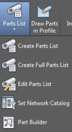
Figure 13.44 The Network Tools panel shown with the Parts List menu expanded
You'll also find Draw Parts In Profile on the Network Tools panel. This tool adds the selected pipe network objects into an existing profile view.
The Analyze Panel
The Analyze panel (Figure 13.45) contains three tools for performing various checks on a pipe network. Using the drop-down menu for Interference Check, you have these options:
- Create Interference Check Allows you to create an interference check between parts, whether or not they are on the same network.
- Interference Check Properties When you select the Interference Check Properties tool, you will be prompted to select Interference, and then the Interference Check Properties dialog will open:
- The Information tab displays basic information such as the name of the interference check set, style, render material, and layer.
- The Criteria tab contains specific editable items, such as whether to use 3D proximity check, distance, and scale factors.
- The Statistics tab is a combined listing of the other tabs but also allows you to see the networks used for the interference check.
- Interference Properties The Interference Properties tool will give you information about a single interference location in your drawing. This differs from the Interference Check Properties in that you can't change the criteria from here. You see only the following information about a specific instance of interference:
- Information tab (where you can name the individual interference objects and change the style and render material)
- Statistics tab (which contains information about the networks causing the selected interference and its location)
- Edit Interference Style This tool will prompt you to select an interference object (by default a brown, circular block). After selecting the interference object, this opens the Interference Style dialog, where you can change the visual parameters for the interference object. For more on styles, see Chapter 19.
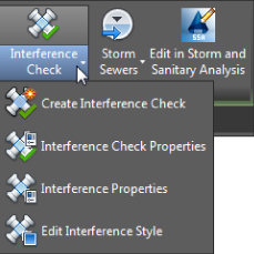
Figure 13.45 The Analyze panel with Interference Check expanded
Storms Sewers commands interact with the Hydraflow Storm Sewers Extension. Hydraflow is a separate program that is included with Civil 3D. An in-depth discussion of Hydraflow is beyond the scope of this book; see the Hydraflow Storm Sewers Extension help files for more information.
Choosing Edit In Storm And Sanitary Analysis opens the Storm and Sanitary Analysis (SSA) program. For more on SSA, see this book's website for a bonus chapter, “Storm and Sewer Analysis.”
The Launch Pad Panel
The Launch Pad panel (Figure 13.46) contains the following tools:
- Alignment From Network Allows you to create an alignment from pipe network parts
- Storm Sewers Launches the Hydraflow Storm Sewers program
- Hydrographs Launches the Hydraflow Hydrographs program
- Express Opens the Hydraflow Express program
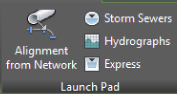
Figure 13.46 The Launch Pad panel
Hydraflow Storm Sewers, Hydraflow Hydrographs, and Hydraflow Express are separate programs that are included with Civil 3D. An in-depth discussion of these programs is beyond the scope of this book; see the relevant Hydraflow help files for more information.
Editing with the Network Layout Tools Toolbar
You can also edit your pipe network by retrieving the Network Layout Tools toolbar. This is accomplished by selecting a pipe network object and choosing Edit Network from the contextual tab. You can also access the contextual tab via the Modify tab of the ribbon and click Pipe Network on the Design panel.
Once the toolbar is up, you can continue working exactly the way you did when you originally laid out your pipe network.
This exercise will give you hands-on experience in making a variety of edits to a waste water and storm drainage pipe network:
- Open the
1305_PipeEditing.dwg(1305_PipeEditing_Metric.dwg) file.This drawing includes a waste water network and a storm drainage network, as well as some surfaces and alignments. For metric users, the structure family names end with SI.
- Select the structure STM STR 3 in the drawing. It is labeled with the structure name showing.
- From the Pipe Networks contextual tab Modify panel, click Swap Part.
- Select the 2 × 4 (1,500 × 750 mm) Rectangular Junction Structure structure from the Rectangular Junction Structure NF (Rectangular Structure Slab Top Rectangular Frame SI for metric users), and click OK.
- Select the newly replaced catch basin so that you see the two structure grips.
- Use the rotational grip and your nearest Osnap to align the catch basin to the centerline of the pipe, as shown in Figure 13.47.
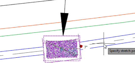
Figure 13.47 Rotate the catch basin into place along the curb.
- Press Esc to clear the selection.
- In the Prospector tab of Toolspace Pipe Networks Networks Waste Water Network, click the Structures branch.
At the bottom of Toolspace, you should see a list of structures present in the network.
- Scroll through the Structures list and locate SAN STR 7. (You will probably need to expand the width of the Name column to view the structure names.)
- Right-click SAN STR 7 and click Pan To.
- Again, right-click SAN STR 7 in the list. This time, click Delete. Select Yes at the prompt.
Next, you will use the AutoCAD dynamic input tool to force pipe lengths to the desired value.
- At the command line, type
DYNMODEand press ↵. - Type
3and press ↵.Your DYNMODE setting may already be set to a value of 3, meaning dimensional input will appear. This step ensures that dynamic input will allow you to enter a total length for the pipe.
- If dynamic input is not already on, press F12 to enable it. Make sure that nothing is selected by pressing the Esc key until everything is cleared. Select the waste water pipe that is labeled in the north of the drawing along the Frontenac Drive alignment.
- Click the triangular Endpoint grip on the right end of the pipe.
Notice the tooltips at your cursor with information about the length of the pipe.
- Press the Tab key to switch the input to the overall length of the pipe. Enter 200′ (60.96 m), as shown in Figure 13.48.
Figure 13.48 Lengthen the pipe to 200′ (60.96 m).
Note that this is the 3D Center To Center Pipe length. Next, you will add a structure to the end of the pipe you just modified.
- Select any pipe in the Waste Water Network. In the Pipe Networks contextual tab Modify panel, click Edit Pipe Network.
- From the Structures list, set the structure to SMH from the Concentric Cylindrical Structures NF family.
- From the Draw Pipes And Structures drop-down, set the option to Structures Only. Place the structure in the drawing at the end of the pipe you lengthened previously. Make sure you can see the connection glyph before you click to add the structure.
- Press Esc to clear the selection.
- Select STM STR 3 in the drawing (this is the structure you modified at the beginning of this exercise), and from the Pipe Networks contextual tab Modify panel, click Structure Properties.
- Switch to the Part Properties tab, scroll down to the Sump Depth field, and change the value to 0′ (0 m).
- Click OK to exit the Structure Properties dialog. Press Esc to clear the selection.
- Select any pipe or structure from the Waste Water Network.
- From the Pipe Networks contextual tab Modify panel, click Edit Pipe Network.
- From the Network Layout Tools, click Pipe Network Vistas.
This will bring up the Panorama interface, which will allow you to rename the structures.
- Make sure that the active Panorama tab is set to Structures.
- In the Name column heading, widen the column so you can see the full name of the structures in the list. (You can widen a column in all spreadsheet-like views in Civil 3D, much as you would in Microsoft Excel.)
- Double-click the cell in the Name column for SAN STR 1.
- Clear the text that is there and type MH 1.
- Repeat steps 29 and 30 for SAN STR 2 through SAN STR 4, renaming each but keeping the number. Close the vista and then close the toolbar.
- Save and close the drawing.
For your reference, completed versions of the drawing (1305_PipeEditing_FINISHED.dwg and 1305_PipeEditing_METRIC_FINISHED.dwg) are available with the rest of this book's download.
Creating an Alignment from Network Parts
On some occasions, certain legs of a pipe network require their own stationing. Perhaps most of your pipes are shown on a road profile, but the legs that run offsite or through open space require their own profiles. Whatever the reason, it's often necessary to create an alignment from network parts. To do so, follow these steps:
- Open the
1306_Alignment.dwg(1306_Alignment_METRIC.dwg) file. - Select the CB1 structure, which will be the first structure in the network on the east side of the Syrah Way alignment.
 On the Pipe Networks contextual tab Launch Pad panel, select Alignment From Network.
The command line will read
Select next Network Part or [Undo].- Select the STM STR 7 structure, which will be the last structure on the alignment. Notice that all the pipes and structures between the two selected structures have been highlighted. If any of the pipes or structures are not connected, the selecting set won't work as expected.
- Press ↵, and a Create Alignment - From Pipe Network dialog will appear that is almost identical to the one you see when you create an alignment from the Alignments menu.
- Name your alignment Storm CL.
- Leave the default Alignment type.
- Set the Alignment Style to Layout and the Alignment Label Set to Major And Minor Only.
- Notice the Create Profile And Profile View check box on the last line of the dialog. Leave the box selected and click OK.
- The Create Profile From Surface dialog will appear (see Figure 13.49).
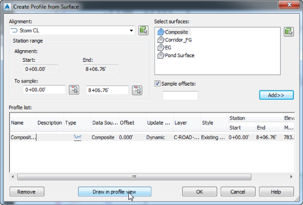
Figure 13.49 The Create Profile From Surface dialog
- Select the Composite surface, and click Add.
- Click Draw In Profile View.
The Create Profile View Wizard will appear (see Figure 13.50). Make sure your settings match those in the figure.
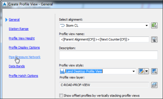
Figure 13.50 The Create Profile View Wizard
- Click Pipe/Pressure Network to jump to that page.
You should see a list of pipes and structures in your drawing.
- Verify that Yes is selected for each pipe and structure in the Storm Network only. By default only the previously selected pipes and structures will be set to Yes on this tab.
- Click Create Profile View, and place the profile view to the right of the site plan. Notice that the profile shows the pipe network from upstream to downstream.
Seven structures and six pipes will be drawn in a profile view, which is based on the newly created alignment (see Figure 13.51).
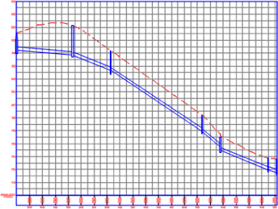
Figure 13.51 The completed profile view
- Select the created alignment and from the contextual tab, Modify Panel, choose the Reverse Direction. On the warning prompt click OK.
Notice how the profile view updated and the pipe network is displayed from downstream to upstream.
- Save and close the drawing.
For your reference, completed versions of the drawing (1306_Alignment_FINISHED.dwg and 1306_Alignment_METRIC_FINISHED.dwg) are available with the rest of this book's download.
Drawing Parts in Profile View
![]() To add pipe network parts to an existing profile view, select a network part, and choose Draw Parts In Profile from the Network Tools panel of the Pipe Networks contextual tab. When you're using this command, it's important to note that only selected parts are drawn in your chosen profile view.
To add pipe network parts to an existing profile view, select a network part, and choose Draw Parts In Profile from the Network Tools panel of the Pipe Networks contextual tab. When you're using this command, it's important to note that only selected parts are drawn in your chosen profile view.
Profiles and profile views are always cut with respect to an alignment. Therefore, pipes are shown in the profile view on the basis of how they appear along that alignment or how they cross that alignment. Unless your alignment exactly follows the centerline of your network parts, your pipes will likely show some drafting distortion.
Let's look at Figure 13.52 as an example. This particular jurisdiction requires that all utilities be profiled along the road centerline. There are a road centerline and a storm network that jogs across the road to connect with another catch basin.
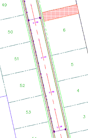
Figure 13.52 These pipe lengths will be distorted in profile view.
At least two potentially confusing elements show up in your profile view. First, the distance between structures (2D Length – Center To Center) isn't the same between the plan and the profile (see Figure 13.53) because the storm pipe doesn't run parallel to the alignment. Because the labeling reflects the network model, all labeling is true to the 2D Length – Center To Center or any other length you specify in your label style.
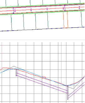
Figure 13.53 Pipe labels in plan view (top) and profile view (bottom)
The second potential issue is that the invert of your crossing storm pipe is shown at the point where the storm pipe crosses the alignment and not at the point where it connects to the storm sewer structure (see Figure 13.54).
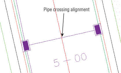
Figure 13.54 The invert of a crossing pipe is drawn at the location where it crosses the alignment.
Editing Pipe Networks in Profile View Using Grips
Although you can't make changes to certain part properties (such as pipe length) in profile view, pipes and structures both have special grips for changing their vertical properties in profile view.
When selected, a structure has two grips in profile view (see Figure 13.55). The first is a triangular-shaped grip representing a rim insertion point. This grip can be dragged up or down, and it affects the model structure-insertion point.
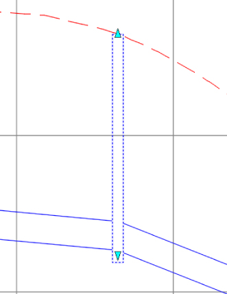
Figure 13.55 A structure has two grips in profile view.
Moving this grip can affect your structure insertion point in two ways, depending on how your structure properties were established:
- If your structure has Automatic Surface Adjustment set to True, grip-editing this Rim Insertion Point grip changes the surface adjustment value. If your reference surface changes, your rim will change along with it, plus or minus the surface adjustment value.
- If your structure has the Automatic Surface Adjustment set to False, grip-editing this Rim grip modifies the insertion point of the rim. No matter what happens to your reference surface, the rim will stay locked in place.
Typically, you'll use the Rim Insertion Point grip only in cases where you don't have a surface for your rims to target, or if you know there is a desired surface adjustment value. It's tempting to make a quick change instead of making the improvements to your surface that are fundamentally necessary to get the desired rim elevation. One quick change often grows in scope. Making the necessary design changes to your target surface will keep your model dynamic and, in the long run, will make editing your rim elevations easier.
The second grip is a triangular grip located at the sump depth. This grip doesn't represent structure invert. In Civil 3D, only pipes truly have invert elevation. The structure uses the connected pipe information to determine how deep it should be. When the sump has been set at a depth of 0, the sump elevation equals the invert of the deepest connected pipe.
This grip can be dragged up or down. It affects the modeled sump depth in one of two ways, depending on how your structure properties are established:
- Control Sump By Depth If your structure is set to control sump by depth, editing with the Sump grip changes the sump depth.
The depth is measured from the structure insertion point. For example, if the original sump depth was 0, grip-editing the sump 0.5′ (15.24 cm) lower would be the equivalent of creating a new sump rule for a 0.5′ (15.24 cm) depth and applying the rule to this structure. This sump will react to hold the established depth for any changes that would affect the invert of the lowest connected pipe. This triangular grip is most useful in cases where most of your pipe network will follow the sump rule applied in your parts lists, but selected structures need special treatment.
- Control Sump By Elevation If your structure is set to control sump by elevation, adjusting the Sump grip changes that elevation.
When sump is controlled by elevation, sump is treated as an absolute value that will hold regardless of the structure insertion point. For example, if you grip-edit your structure so its depth is 8.219′ (2.51 m), the structure will remain at that depth regardless of what happens to the inverts of your connected pipes. The Control Sump By Elevation parameter is best used for existing structures that have surveyed information of absolute sump elevations that won't change with the addition of new connected pipes.
When selected, a pipe end has three grips in profile view (see Figure 13.56). You can grip-edit the invert, crown, and centerline elevations at the structure connection using these grips, resulting in the pipe slope changing to accommodate the new endpoint elevation.
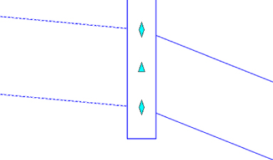
Figure 13.56 Three grips for a pipe end in profile view
When selected, a pipe in profile view has one grip at its midpoint (see Figure 13.57). You can use this grip to move the pipe vertically while holding the slope of the pipe constant.
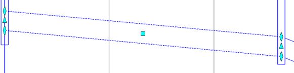
Figure 13.57 Use the midpoint grip to move a pipe vertically.
You can access pipe or structure properties by choosing a part, right-clicking, and choosing Pipe or Structure Properties.
Removing a Part from Profile View
If you have a part in profile view that you'd like to remove from the view without deleting it from the pipe network entirely, you have a few options.
AutoCAD Erase can remove a part from profile view; however, that part is then removed from every profile view in which it appears. If you have only one profile view or if you're trying to delete the pipe from every profile view, this is a good method to use.
Be careful when using the Del key or the Erase command on objects in plan view. Keep in mind that deleting any object from plan view removes the object outright, which includes pipe network parts. Use your Esc key liberally before selecting items to remove; this will help you avoid unintended deletion of items. Of course, if you accidentally blow away something, Undo will bring it back, but it isn't recommended, since pipe network corruption might occur.
A better way to remove parts from a particular profile view is through the Profile View Properties. You can access these properties by selecting the profile view and from the contextual tab select Profile View Properties from the Modify View panel.
The Pipe Networks tab of the Profile View Properties dialog (see Figure 13.58) provides a list of all pipes and structures that are shown in that profile view. You can deselect the check boxes next to parts you'd like to omit from this view.
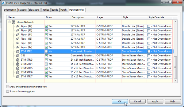
Figure 13.58 Deselect parts to omit them from a view.
At the bottom of the Profile View Properties dialog is a check box for Show Only Parts Drawn In Profile View. This check box is off by default so that you can see every possible pipe and structure. When it is checked on, the Pipe Network tab will hide any pipes that are not visible in the profile view you are examining.
Don't forget about the Show Only Crossing Pipes option. When this option is on, the list will narrow to only pipes that cross the alignment related to the profile view. This is a great help when you need to override the style of crossing pipes to show them as ellipses rather than linear pipes. Style overrides are discussed in more detail in the section of this chapter called “Adding Pipe Network Labels.”
Showing Pipes That Cross the Profile View
If you have pipes that cross the alignment related to your profile view, you can show them with a crossing style. A pipe must cross the parent alignment to be shown as a crossing in the profile view. The location of a crossing pipe is always shown at the elevation where it crosses the alignment (see Figure 13.59).
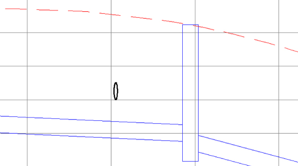
Figure 13.59 A pipe crossing a profile
When pipes enter directly into profiled structures, they can be shown as ellipses through the Display tab of the Structure Style dialog (see Figure 13.60). See Chapter 19 for more information about creating structure styles.
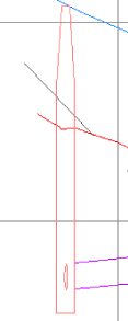
Figure 13.60 Pipes that cross directly into a structure can be shown as part of the structure style.
The first step to display a pipe crossing in profile is to add the pipe that crosses your alignment to your profile view by either selecting the pipe and from the contextual tab selecting Draw Parts In Profile from the Network Tools panel and then selecting the profile view or by checking the appropriate boxes on the Pipe Network tab of the Profile View Properties dialog. When the pipe is added, it's distorted when it's projected onto your profile view—in other words, it's shown as if you wanted to see the entire length of pipe in profile (see Figure 13.61).
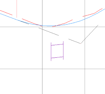
Figure 13.61 The pipe crossing is distorted.
The next step is to override the pipe style in this profile view only. Changing the pipe style through pipe properties won't give you the desired result, because that will affect the visibility of every single instance of the pipe. You must override the style on the Pipe Networks tab of the Profile View Properties dialog (see Figure 13.62).
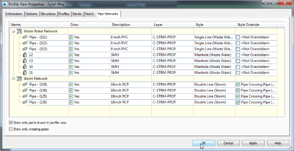
Figure 13.62 Use Style Override to display correctly a crossing in the Profile View Properties dialog.
Locate the pipe you just added to your profile view and scroll to the last column on the right (Style Override). Select the Style Override check box and choose your pipe crossing style. Click OK. Your pipe should appear as an ellipsis.
If your pipe appears as an ellipsis but suddenly seems to have disappeared in the plan and other profiles, chances are good that you didn't use Style Override but accidentally changed the pipe style. Go back to the Profile View Properties dialog and make the necessary adjustments; your pipes will appear as you expect.
Adding Pipe Network Labels
Once you've designed your network, it's important to annotate the design. This section focuses on pipe network–specific label components in plan and profile views (see Figure 13.63).
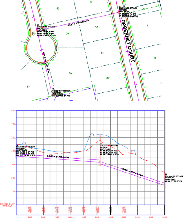
Figure 13.63 Sample of pipe network labels in plan view (top) and in profile view (bottom)
Like all Civil 3D objects, the Pipe and Structure label styles can be found in the Pipe and Structure branches of the Settings tab in Toolspace and are covered in Chapter 18.
Creating a Labeled Pipe Network Profile with Crossings
This exercise will apply several of the concepts in this chapter to give you hands-on experience producing a pipe network profile that includes pipes that cross the alignment. You will have another chance to practice creating an alignment from a pipe network and associating the new alignment to the parts. You will also practice overriding pipe display in the Profile View Properties. There are storm pipes that cross the centerline nearly perpendicular to the alignment. You will show these as ellipses in the profile view.
- Open the
1307_PipeLabels.dwg(1307_PipeLabels_METRIC.dwg) file. (It's important to start with this drawing rather than use the drawing from an earlier exercise.) Note that surface numbering may differ between drawings so these numbers have been omitted from the exercise. - Locate waste water structure 16 (near station 5+15 or 0+160 of Cabernet Court), select it to open the Pipe Networks contextual tab, and then select Alignment From Network on the Launch Pad panel.
- When prompted to
Select Next Network Part, select structure 18 and press ↵ to create an alignment from the waste water network. - Choose the following options in the Create Alignment From Network Parts dialog:
- Site: <none>
- Name: SMH16 to SMH18 Alignment
- Alignment Type: Miscellaneous
- Alignment Style: _None
- Alignment Label Set: _No Labels
- Create Profile And Profile View check box: Selected
- Click OK.
- In the Create Profile From Surface dialog, highlight the EG and Corridor FG surfaces, and click Add.
- Change the Style for Corridor FG – Surface to Design Profile by clicking on the Style column cell for the profile and selecting the specified style.
- Click Draw In Profile View to open the Create Profile View dialog.
- Set Profile View Style to Land Desktop Profile View and click the Next button in the Create Profile View Wizard until you reach the Pipe/Pressure Network Display page.
You should see a list of pipes and structures in your drawing. Make sure Yes is selected for each pipe and structure under Waste Water Network.
- Click Create Profile View. At the
Select profile view origin:prompt, click to place the profile view to the right of the site plan. - Press the Esc key to complete the command. Select either a pipe or a structure in the profile view to open the Pipe Networks contextual tab. On the Labels & Tables panel, select Add Labels Entire Network Profile. Press Esc to deselect pipe networks parts.
The alignment information is missing from your structure labels because the alignment was created after the pipe network.
- Select one of the pipes in the drawing from either plan or profile view.
- From the Pipe Networks contextual tab Modify panel, click Edit Pipe Network.
- From the Network Layout Tools, click Pipe Network Vistas.
- Verify that you are on the Structures tab of Panorama.
- Select structures 16 through 18 in Panorama using Shift+click. You may need to left-click the Name column header to sort by name.
- Scroll to the right until you see the Reference Alignment column.
- Right-click the column header and select Edit. Choose SMH16 To SMH18 Alignment from the Select Alignment dialog and click OK.
- Close Panorama by clicking the green check mark on the Pipes and Structures tabs. You may need to enter
REGENALLat the command line to see your updated structure labels. Close the Network Layout Tools toolbar. - Pan your drawing until you see the Storm layout located on Syrah Way in the plan view.
The waste water pipe network has already been laid out on the Syrah Way profile view. You want to show the storm where it crosses the waste water so you can adjust the pipe elevations if necessary.
- Press Esc a few times to make sure no other parts are selected. Then select the four pipes that cross perpendicular to the Syrah Way alignment.
- In the Pipe Networks contextual tab Network Tools panel, select Draw Parts In Profile.
- Select the Syrah Way profile view.
- Press Esc to ensure no extra objects are selected, and then select the profile view and pick Profile View Properties from the Profile View contextual tab.
- On the Pipe Networks tab of the Profile View Properties dialog, place a check mark next to Show Only Parts Drawn In Profile View.
- Select all four Storm Network pipes shown in Figure 13.62, and override the pipe style in this profile view by placing a check mark next to
<Not Overridden>in the Style Override column. You will be prompted to pick the pipe style and select the Pipe Crossing Pipe (Storm) style. Click OK when you have selected the style. - When overrides have been set for all four pipes, click OK and Esc to deselect any items.
Your crossing pipes will resemble Figure 13.64.
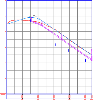
Figure 13.64 The completed exercise with crossing pipes
- Adjust the elevations of the crossing pipes as needed. Close the Network Layout Tools toolbar. Save and close the drawing.
You can control the accuracy of the pipe crossing representation by changing the value of the
facetdevvariable.
For your reference, completed versions of the drawing (1307_PipeLabels_FINISHED.dwg and 1307_PipeLabels_METRIC_FINISHED.dwg) are available with the rest of this book's download.
Using Pipe and Structure Labels
In earlier exercises, you had a sneak peek at adding labels for structures. Civil 3D makes no distinction between a plan label and a profile label. The same label style can be used in both places. In this chapter, you will use label styles that are already part of the drawing.
To create your own pipe labels from scratch, see Chapter 18.
Creating an Interference Check
When designing, you must make sure pipes and structures are appropriately separated. You can perform some visual checks by rotating your model in 3D and plotting pipes in profile and section views (see Figure 13.65). Civil 3D also provides a tool called Interference Check that makes a 3D sweep of your pipe networks and lets you know if anything is too close for comfort.
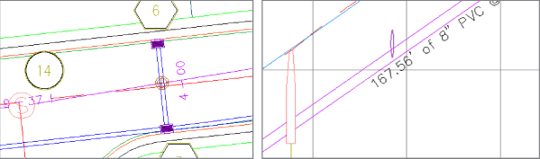
Figure 13.65 Two pipe networks may interfere vertically where crossings occur (left). Viewing your pipes in profile view can also help identify conflicts (right).
The following exercise will lead you through creating a pipe network and using Interference Check to scan your design for potential pipe network conflicts:
- Open the
1308_Interference.dwg(1308_Interference_METRIC.dwg) file. The drawing includes a waste water pipe network and a storm drainage pipe network. - Select a part from either network, and on the Pipe Networks contextual tab Analyze panel, choose Interference Check Create Interference Check, as shown in Figure 13.66.
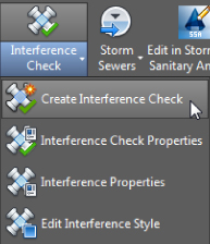
Figure 13.66 Creating an interference check
You'll see the
Select a part from the same network or different network:prompt. - Select a part from the network that hasn't already been chosen.
The Create Interference Check dialog will appear (Figure 13.67).
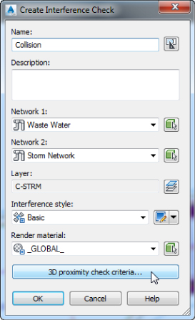
Figure 13.67 The Create Interference Check dialog
- Name the Interference Check Collision, and confirm that Waste Water and Storm Network appear in the Network 1 and Network 2 boxes.
- Click the 3D Proximity Check Criteria button, and the Criteria dialog will appear (see Figure 13.68).
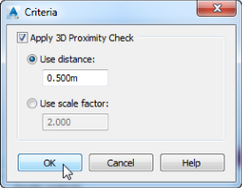
Figure 13.68 Criteria for the 3D proximity check
- You're interested in finding all network parts that are within a certain tolerance of one another, so place a check mark next to Apply 3D Proximity Check. Then enter 1.5 (0.5 for metric users) in the Use Distance box.
This setting creates a buffer to help find parts in all directions that might interfere. If you forget to check Apply 3D Proximity Check, only direct, physical collisions will be listed as collisions.
- Click OK to exit the Criteria dialog, and click OK to run the Interference Check.
You should see a dialog that alerts you to three interferences.
- Click OK to dismiss this dialog.
- On the Prospector tab of Toolspace Pipe Networks, expand the Interference Checks branch. Right-click Collision and select Zoom To.
A small marker will appear at each location where interference occurs, as shown in Figure 13.69.
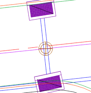
Figure 13.69 The interference marker in plan view
- Make sure there is no item selected by pressing the Esc key a few times. Then select any one of the interference markers, the pipes that intersect, or the nearby inlets.
 From the Multiple contextual tab General Tools panel, click Object Viewer.
- In the upper-left corner of Object Viewer, click the Visual Style drop-down. Change the Visual Style to Conceptual. Choose SW Isometric in upper-right corner of Object Viewer.
The interference marker will appear in 3D, as shown in Figure 13.70.
Figure 13.70 The interference marker in 3D
- Use the ViewCube in Object Viewer to navigate in 3D.
- Once you have examined the 3D objects, close Object Viewer. Save and close the drawing.
Note that each instance of interference is listed in the preview pane for further study.
For your reference, completed versions of the drawing (1308_Interference_FINISHED.dwg and 1308_Interference_METRIC_FINISHED.dwg) are available with the rest of this book's download.
Editing your pipe network will flag the interference check as “out of date.” You can rerun Interference Check by right-clicking Interference Check in Prospector. You can also access the Interference Check Properties to edit your criteria in this context menu.
Creating Pipe Tables
Just as with parcels and labels, the process of labeling pipes can turn into a mess when all the labels are set on the plan (see Figure 13.71). In this section, you will explore the process of creating tables for pipes and structures.
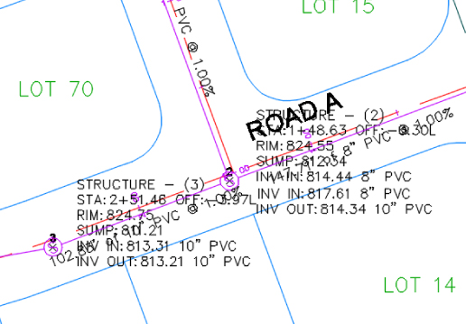
Figure 13.71 Crowded pipes and structure labels on a plan
Exploring the Table Creation Dialog
Because the Structure Table Creation dialog and Pipe Table Creation dialog are similar (see Figure 13.72), we will cover both of them in this section.
- The Table Style option allows you to select a table look or style. You can select the available styles from the arrow to the right of the Table Style name. You can also create new, copy, edit, or pick a table style from an existing table in the drawing. For more on table styles, see Chapter 18.
- The Table Layer option shows the layer where the table is placed.
- With the By Network radio button selected, you can select the network to create a table from the drop-down, or you can use the Pick icon to select the network from the drawing.
- With the Multiple Selection radio button selected and by using the Pick icon, you can select structures or pipes (depending on which table type is selected) from the drawing. You can pick pipes or structures regardless of the network.
- The Split Table check box allows you to split the table if it becomes too large. You can specify the maximum number of rows per table and the maximum number of tables per stack. Additionally, you can set the offset distance between the stacked tables.
- You can choose whether you want the split tables tiled across or down.
- In the Behavior section, choose Static or Dynamic. A static table will not update if any changes are made to the pipe network, such as swapping a part. Dynamic will update the table to those changes.
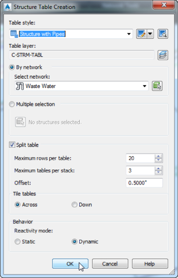
Figure 13.72 The Structure Table Creation dialog box
In the following exercise, you will create a pipe network table for the waste water structures:
- Open the
1309_PipeTable.dwg(1309_PipeTable_METRIC.dwg) file. - Click on the MH1. This is a structure from the waste water network.
- From the Pipe Networks contextual tab Labels & Tables panel, select Add Tables Add Structure.
The Structure Table Creation dialog opens.
- Verify that the By Network option is set to Waste Water. Click OK to accept the default settings (shown in Figure 13.72).
- Place the table to the right of your plan.
The table should look similar to Figure 13.73.
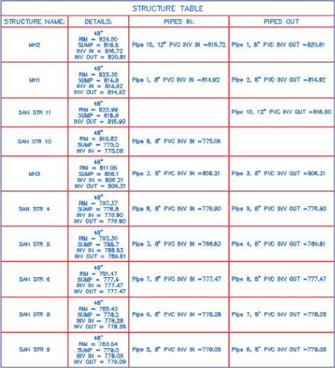
Figure 13.73 The finished structure table
The process of creating tables for pipes is similar to the process for creating tables for structures.
- Press Esc to clear the current selection and click any waste water pipe.
Note that as long as you have the Pipe Networks contextual tab open you can create a table for either pipes or structures.
- From the Pipe Networks contextual tab Labels & Tables panel, select Add Tables Add Pipe.
The Pipe Table Creation dialog opens (Figure 13.74).
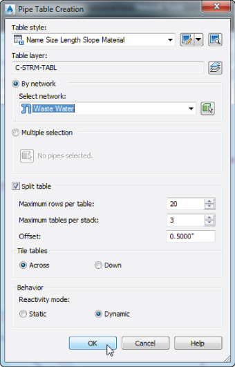
Figure 13.74 The Pipe Table Creation dialog
- Verify that the By Network option is set to Waste Water. Click OK to accept the default settings.
- Place the table to the right of the structure table.
The pipe table should look similar to Figure 13.75. (Metric users will see Reinforced Concrete in the Material column.)
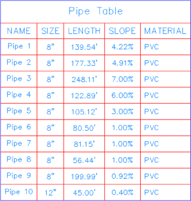
Figure 13.75 The finished pipe table
The Table Panel Tools
When you click a table, the Table contextual tab opens and has several tools available (Figure 13.76). You'll look at each in this section.
Figure 13.76 The Table contextual tab
The General Tools Panel
The tools here are the same as mentioned earlier when the pipe network tools were discussed.
The Modify Panel
The Modify panel contains the following tools:
- Table Properties This tool opens the Table Properties dialog. With it, you can set the table style and choose whether to split the table with all the options mentioned earlier. In addition, you can force realignment of stacks, and if the reactivity mode is set to Static, you can force content updating.
- Edit Table Style This tool is located under the Table Properties drop-down and opens the Table Style dialog. For more on editing table styles, see Chapter 18.
- Static Mode This tool turns a dynamic table into a static table.
- Update Content This tool forces an update on a table.
- Realign Stacks This tool readjusts the table columns back to the default setting. This is especially useful after changing the annotation scale of the view or viewport.
- Add Items This tool adds pipe data to the table that was added after the table was created.
- Remove Items This tool removes pipe or structure objects from a table.
- Replace Items This tool allows you to replace the current select set with a new one.
Setting and Using a Pressure Pipes Network
Pressure pipes work differently than gravity-flow pipe systems within Civil 3D. Much of the need for custom parts such as valves or hydrants is eliminated with these systems. In this section, you'll learn how easy it is to model water, gas, or other pressurized systems in 3D.
Pressure Network Parts List
Like gravity-based networks, a pressure network starts with a parts list. All of the parts available in Civil 3D are based on standards established by the American Water Works Association (AWWA) and are listed in both inches and millimeters.
Pressure parts lists contain pipes, fittings, and appurtenances. You'll find the style for each object in the parts list, but instead of rules, pressure pipe design checks are tucked into the command settings.
Examples of Pressure Pipe Network parts lists include
- Water main and service connections
- Ductile iron pipe
- Tees, elbows, and crosses
- Valves
- Gas main
- PVC pipe
- Valves
Under the Hood of the Pressure Network
Before you can create a Pressure parts list, you must determine the catalog from which you will be working. Set the pressure network catalog by going to the Home tab ![]() Create Design panel (expand the panel to view the additional tools) and selecting Set Pressure Network Catalog, as shown in Figure 13.77.
Create Design panel (expand the panel to view the additional tools) and selecting Set Pressure Network Catalog, as shown in Figure 13.77.
Figure 13.77 Setting the pressure network catalog
Set the path to the Pressure Pipes Catalog folder to C:ProgramDataAutodeskC3D 2015enuPressure Pipes Catalog. Click the folder icon to choose either the Metric or the Imperial database, depending on your needs.
The catalog database file determines the join type between pressure network parts. In modern water main construction, the most commonly used join type is the push-on type, which is the default pressure database. As shown in Figure 13.78, with Imperial units you have three options:
- Imperial_AWWA_Flanged
- Imperial_AWWA_Mechanical
- Imperial_AWWA_PushOn
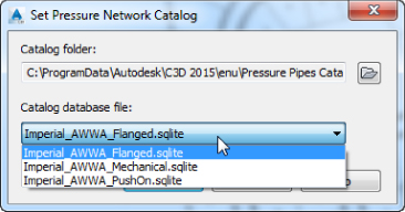
Figure 13.78 Setting your catalog database file
Metric_AWWA_PushOn is currently the only available option for metric users.
These differ slightly in their options for pipes, fittings, and appurtenances. Only one type of pressure network catalog can be active at a time. A parts list can have parts from only one catalog in it; for example, you cannot mix and match push-on with mechanical parts. You can, however, have multiple Pressure parts lists in your template; each can pull parts from the various catalog database files. You can place parts from different parts lists into the same pressure network, as long as the parts are meant for the same diameter and pressure.
Creating a Pressure Parts List
In the Settings tab of Toolspace, you will find the listing for pressure networks. The Pressure Networks ![]() Parts List branch is where you will create a parts list. In the case of pressure networks, a parts list contains three components:
Parts List branch is where you will create a parts list. In the case of pressure networks, a parts list contains three components:
- Pressure Pipes Ductile iron of various sizes can be added. Like the gravity networks, each part can have a style. Furthermore, different sizes within the part families can have styles, which can help you identify them in the graphic.
- Fittings Fittings such as tees, crosses, and elbows are specified in this tab.
- Appurtenances Valves are specified in the Appurtenances tab.
In the following exercise, you will create a Pressure Network parts list:
- Open the
1310_Pressure.dwg(1310_Pressure_METRIC.dwg) drawing, which you can download from this book's web page.This file is set up with a layer state that makes other objects gray. This will help you focus on the placement of pressure pipe network objects.
- On the Home tab Create Design panel, click the arrow to view additional tools and select Set Pressure Network Catalog.
- In the Set Pressure Network Catalog dialog verify that Catalog Database File is set to
Imperial_AWWA_PushOn.sqlite(Metric_AWWA_PushOn.sqlite). (You might need to change the Catalog Folder path to access the correct catalog database file for the metric drawing.) Click OK. - On the Settings tab of Toolspace Pressure Network, expand the Pressure Network branch, right-click Parts Lists, and select New.
- In the Pressure Network Parts List dialog, switch to the Information tab. Rename the Pressure Network parts list Watermain.
- Switch to the Pressure Pipes tab. Right-click New Parts List and select Add Material.
- In the Pressure Network Catalog dialog, place a check mark next to Ductile Iron and click OK.
- The name of the Pipe Parts list will update to Watermain. Expand the Watermain branch.
- Right-click Ductile Iron and select Add Size.
- Set the Nominal Diameter value to 10” (250 mm).
- Set the Cut Length value to 20′ (6 m). Leave all other default values, as shown in Figure 13.79, and click OK.
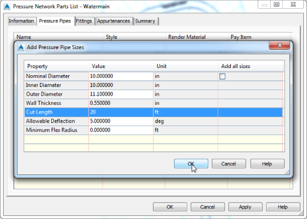
Figure 13.79 Adding ductile iron pipe to the Pressure Network parts list
- Switch to the Fittings tab, right-click New Parts List, and select Add Type.
- In the Pressure Network Catalog dialog, place a check mark next to all three fitting types—Cross, Elbow, and Tee—as shown in Figure 13.80, and then click OK.
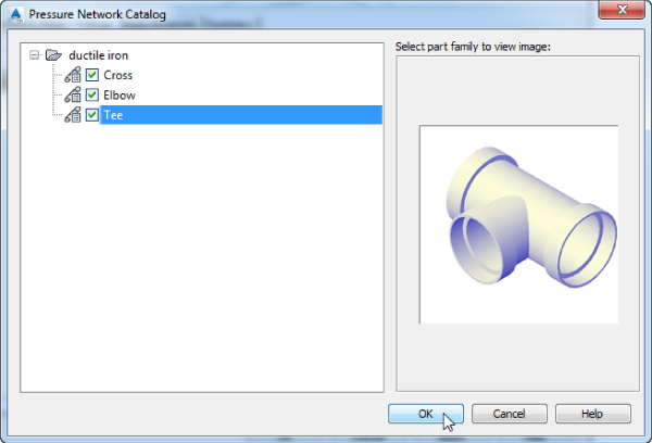
Figure 13.80 Adding fittings to the Pressure Network parts list
Metric users will have only the options for Elbow and Tee.
- Expand the Watermain branch under the Fittings tab if it is not already expanded.
Metric users can skip to step 17.
- Right-click Ductile Iron Cross and select Add Size.
- Change Nominal Diameter to 10 × 10 × 14 × 14. Leave the Allowable Deflection value as 5 degrees, and click OK.
- Right-click Ductile Iron Elbow, and click Add Size.
- Set Bend Angle to 11.25 and set Nominal Diameter to 10 × 10 (250 × 250 mm). Leave the Allowable Deflection value at 5 degrees, which is the default for the size you picked. Click OK.
- Repeat steps 17 and 18 for 22.5-degree and 45-degree elbows, with a nominal diameter of 10 × 10 (250 × 250 mm).
- Right-click Ductile Iron Tee and select Add Size.
- Set Nominal Diameter to 10” (250 mm). Leave Allowable Deflection as 5 degrees. Click OK.
- Switch to the Appurtenances tab.
- Right-click New Parts List and select Add Type.
- Place a check mark next to Gate Valve – Push-On – Ductile Iron – 200 psi (Gate Valve – Push-On – Ductile Iron – 16 Bar) and click OK.
- Expand the Watermain branch under the Appurtenances tab.
- Right-click the new gate valve and select Add Size.
- Change the Nominal Diameter value to 10 × 10 (250 × 250 mm) and click OK.
- Click OK again to finish creating the Watermain Pressure Network parts list, and then save the drawing for use in the next exercise.
You can check your results against
1310_Pressure_A.dwg(1310_Pressure_A_METRIC.dwg), which can be downloaded from the book's website.
Creating a Pressure Network
After you have set your pressure network catalog, created your Pressure Network parts list, and set your design parameters, it is time to draw your first network.
Pressure Networks in Plan View
As you work with pressure pipes, you will see some useful glyphs appear as you draw.
As shown in Figure 13.81, selecting a pressure pipe will give you tools to modify and continue your design.
- Location The Location glyph moves the pipe both horizontally and vertically and will disconnect it from the adjoining fittings or appurtenances.
- Deflection The Deflection glyph will change the angle at which the pipe sits in the adjoining fitting. When this glyph is active, you will see a fan-shaped guide indicating the allowable deflection from the fitting properties in the Pressure Network parts list. You are able to move the pipe beyond the guide, but will receive design check errors when analyzing the network. You will take a closer look at design checks later in this chapter.
- Continue Layout Continue Layout will help you pick up where you left off when working with pressure pipes. When you use this glyph from the end of a pipe, it will create a bend using the elbows from your Pressure Network parts list.
- Lengthen Lengthen will allow you to stretch or shorten a pipe. When used with dynamic input, you can set pipes to a specified 3D length. See the section on working with pipes and dynamic input earlier in the “Editing with the Network Layout Tools Toolbar” section.
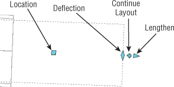
Figure 13.81 Glyphs on a pressure pipe end
As shown in Figure 13.82, you will encounter more glyphs when working with fittings and appurtenances.
- Slide The Slide glyph is similar to Lengthen, but it can modify a pipe's length when a fitting or appurtenance is already attached.
- Flip The Flip glyph will mirror the part at its center. Flip glyphs are especially handy when working with tees, because it is often necessary to change the outlet direction of a tee after it is inserted. Be cautious when using the Flip glyph with elbows, because it may disconnect the adjoining pipe.
- Location Changing the location of a fitting or appurtenance will move the pipe and maintain the connection.
- Continue Layout When you use this grip from a fitting or appurtenance, you are restricted to creating your pipe within the object's deflection tolerance.
- Rotation This grip allows you to rotate your fitting around its z-axis by a defined angle. Note that this grip is available only when the fitting is not connected to any pipe. Upon connection, the grip becomes unavailable.
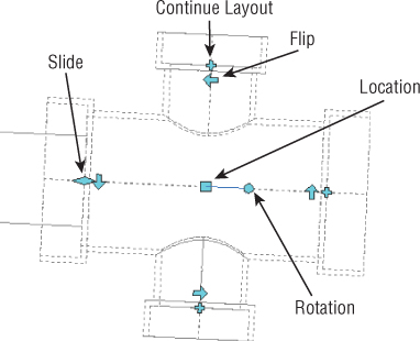
Figure 13.82 Glyphs on a cross fitting
In this exercise, you will create a pressure network. Use the Xs as guides for placement, but don't worry if your pipe network is slightly off from the guides. Due to the 3D nature of the pipes, the restrictions on placement angles within the pressure network parts, and object snap behavior, duplicating an example network exactly would be quite tedious. Get a feel for the pressure network creation tools and have fun! You need to have completed the previous exercise before continuing.
- Continue working in the drawing
1310_Pressure.dwg(1310_Pressure_METRIC.dwg), or if you have not completed the exercise, open1310_Pressure_A.dwg(1310_Pressure_A_METRIC.dwg). Make sure that your catalog is set to the Push-On part catalog, as shown in the previous exercise.As you work through this exercise, you will get the best results if you turn off object snaps, object snap tracking, polar tracking, and/or ortho. Because the pressure pipe tools already have restrictions on how they can be drafted, sometimes these tools conflict with where you want to place the pipe.
- From the Home tab Create Design panel, click Pipe Network Pressure Network Creation Tools, as shown in Figure 13.83.
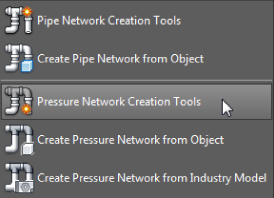
Figure 13.83 Selecting Pressure Network Creation Tools
- In the Create Pressure Pipe Network dialog, name the network Watermain North, and then do the following:
- Set Parts List to Watermain.
- Set Surface Name to Composite.
- Set Alignment Name to Syrah Way.
- Set the pipe, fitting, and appurtenance labels styles as shown in Figure 13.84.
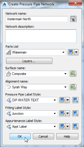
Figure 13.84 Creating your new Watermain North system using pressure pipe network tools
- Click OK.
The ribbon will change to show you the Pressure Network Plan Layout contextual tab, as shown in Figure 13.85.

Figure 13.85 The Pressure Network Plan Layout toolbar
- On the Pressure Network Plan Layout contextual tab Network Settings panel, set the default cover to 4.5’ (1.5 m).
- On the Layout panel, set your Size And Material drop-down to Pipe – 10 In – Push-On – Ductile Iron – 350 psi – AWWA C151 (Pipe – 250 mm – Push-On – Ductile Iron – 25 Bar – AWWA C151).
- Start to place a waterline by clicking the X labeled 1 toward the east end of Syrah Way.
- Place the first bend by clicking near the X labeled 2, to the left.
- At the bend, you are restricted to the bend angles listed in your part network. The Compass glyph (Figure 13.86) that appears represents the elbow angles to the left and right of your pipe. If you had not included multiple elbow angles in your Pressure Pipe Network parts list, only the default elbow angle of 11.25 degrees would be available.
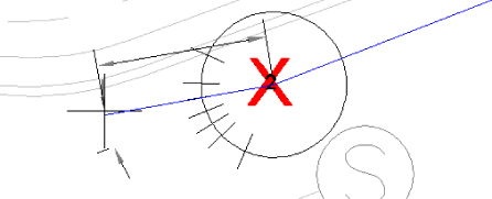
Figure 13.86 The Pressure Pipe Fitting glyph reflects your elbow angles.
- Click the X labeled 3 to place the next pipe end.
- Continue working east to west until you click near the X labeled 8. Press the Esc key.
To keep the pressure pipe on track, you will use the allowable deflection of the elbow to move the pipe closer to the edge of the road.
Make sure your object snaps are off for the next steps, because they will interfere with the pipe modification glyphs.
- Select the pipe section between the X labeled 7 and the X labeled 8, and then use the Deflection glyph to move the end of the pipe up north toward (see Figure 13.87) the approximate center of the green circle in the drawing.
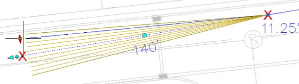
Figure 13.87 Use the Deflection glyph to move the pipe.
- Click the Continue Layout glyph to continue the layout.
- Place the next pipe end at the X labeled 9.
- Continue working west until you reach near the X labeled 10.
Don't worry if you are off the desired location; you can always use the glyphs to edit the pipe location after the fact.
- Press Esc after placing this pipe.
- On the Pressure Network Plan Layout contextual tab Insert panel, change the fitting to Tee–10 in × 10 in- push on-ductile iron-350 psi-AWWA C111/C153 (Tee–250 mm × 250 mm-push on-ductile iron-25 bar-AWWA C110/C111/C153).
 Click Add Fitting.
As you hover your cursor near the end of the pipe, you will see the Add Connection glyph, as shown in Figure 13.88.
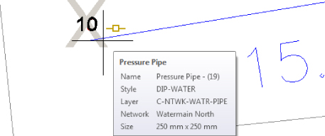
Figure 13.88 Add the fitting to the end of the pipe.
- When the connection glyph is visible, click to add the tee.
- Press Esc to complete the task.
At this point, the tee is in the graphic but it is not positioned in such a way that would make it useful in continuing the design north and south along the intersecting road (Frontenac Drive). To fix this situation, you will disconnect it from the pipe, rotate it, and then reconnect it to the pipe.
- Click the tee in the graphic to select it, and then right-click the part and select Disconnect From Pressure Part, as shown in Figure 13.89. (Note that this command is not available in the contextual tab.)

Figure 13.89 Disconnecting the part in preparation for rotating it
- At the
Select connected pressure part:prompt, select the pipe connected to the tee.Now that the part is disconnected, you are free to rotate it into place. Select the part to reveal its glyphs. A Rotation glyph is visible on the object, which you will use to rotate the part 90 degrees counterclockwise.
- Press F12 to turn on dynamic input if it is not already on.
- Select the tee and then, as shown in Figure 13.90, click the Rotation glyph and enter -90.
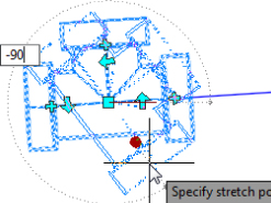
Figure 13.90 Rotate the tee to correct its position before reconnecting.
The tee is now in the correct position, but it must be reconnected to the pipe.
 Select the Location grip, and move the tee to the east until you see the Connection glyph similar to the one you saw in Figure 13.88.
- When you see the Connection glyph, click to set the tee.
You will know the tee is connected properly when the Rotation glyph no longer appears on the selected fitting. Another graphic indication that the tee is connected will be the reappearance of the Slide glyph on the connected end.
- Working north from the tee, click the Continue Layout grip to continue the layout.
- Click to place an elbow at the X labeled 11 and finally the X labeled 12. Press Esc.
- Select the tee again, and working south from the tee, click the Continue Layout grip to continue the layout.
- Click to place a pipe ending at the X labeled 13, and press Esc.
 From the Home tab Layers panel, click Layer Freeze.
- Click one of the Xs to freeze the _PLACEMENT SYMBOLS layer, and press ↵ to complete.
If you no longer see the Pressure Network Plan Layout contextual tab, you can get back to it by selecting any pressure network part, and from the Pressure Networks contextual tab
Modify panel, clicking Edit Network Plan Layout Tools. - Press Esc to deselect any items selected on the screen. On the Pressure Network Plan Layout contextual tab Insert panel, verify that Appurtenance is set to the gate valve-10 inch-push on-ductile iron-200 psi-AWWA C111/C500 (gate valve-250 mm-push on-ductile iron-16 bar for metric users).
 Click Add Appurtenance.
- Place the appurtenance in the drawing by clicking near the end of the north pipe. Be sure to look for the single square Connection glyph that indicates you are connecting to the end of the pipe. If you see the double “boxing gloves” glyph, it means you are about to break the pipe.
Be sure to look for the Attachment glyph before clicking, as shown previously in Figure 13.88. Don't be shy about zooming in close to get a good look at the object with which you are working.
- Repeat the process to place another valve at the south end. Press the Esc key when you've finished. Close the contextual tab to exit the editing mode.
- Save and close the drawing.
Completed versions of this drawing can be found with the dataset for comparison: 1310_Pressure_FINISHED.dwg (1310_Pressure_METRIC_FINISHED.dwg).
Pressure Pipe Networks in Profile View
Pressure pipe networks can do things in profile view that gravity pipes cannot. With pressure pipes, the profile view can be used to change straight pipes to curves and delete parts from the project altogether. It is not a good idea to attempt to add parts to your pressure network in profile view, because the resulting location in plan cannot be controlled.
To access these tools, select any pressure part, and from the Pressure Networks contextual tab ![]() Modify panel, choose Edit Network
Modify panel, choose Edit Network ![]() Profile Layout Tools, as shown in Figure 13.91.
Profile Layout Tools, as shown in Figure 13.91.
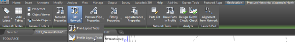
Figure 13.91 Locating the Profile Layout tools
In the following exercise, you will draw the pressure pipe network in profile view and modify the layout using the Follow Surface command:
- Open the
1311_PressureProfile.dwg(1311_PressureProfile_METRIC.dwg) drawing, which you can download from this book's web page. - Select any pressure network part in the drawing.
- From the Pressure Networks contextual tab Launch Pad panel, select Alignment From Network.
- At the
Select first Pressure Network Part (Pipe or Fitting or Appurtenance):prompt, click the Gate Valve at the far right of the drawing. - At the
Select next Pressure Network Part or [Undo]:prompt, select the Gate Valve at the northwest part of the project. - Press ↵ to continue.
The next few steps are exactly the same as when you created an alignment and profile from a gravity pipe network. You will be prompted to create an alignment, sample the surface, and create a profile view.
- In the Create Alignment - From Pressure Network dialog, change the name to Syrah Water.
- Verify that Create Profile And Profile View is checked. Leave all other styles and settings at their defaults and click OK.
- In the Create Profile From Surface dialog, highlight the Composite surface and click Add.
- Click Draw In Profile View.
- In the Create Profile View Wizard, set Profile View Style to Land Desktop Profile View, and leaving all other settings at their defaults click Create Profile View.
- Place the view by clicking a location in the drawing off to the side of the project.
You should see the profile view with your pressure pipe network present in all its glory. As you can see in Figure 13.92, the pipe looks good, except it appears that the pipe cover is inadequate toward the end of the alignment. You can fix this in the steps that follow.
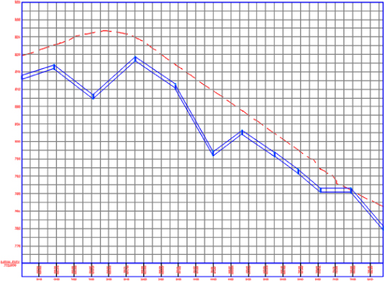
Figure 13.92 Pressure network in profile
- Select a part from the network if the Pressure Networks contextual tab is not already visible.
- From the Pressure Networks contextual tab Modify panel, select Edit Network Profile Layout Tools.
The Pressure Network Profile Layout contextual tab will appear, as shown in Figure 13.93.
Figure 13.93 The Pressure Network Profile Layout contextual tab
 From the Pressure Network Profile Layout contextual tab Modify panel, select Follow Surface.
- At the
Select first pressure part in profile:prompt, select the leftmost valve in the profile view. - At the
Select next pressure part in profile [Enter to finish]:prompt, click the rightmost valve in the profile view and then press ↵ to finish selecting parts. All connected parts in between will become selected. - At the
Enter depth below surface <0.0000>:prompt, enter 4.5 (1.5 for metric users).Your profile view will change to resemble Figure 13.94.
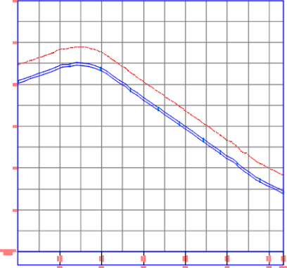
Figure 13.94 The pressure pipe follows the surface.
- Save and close the drawing.
Completed versions of the drawing (1311_PressureProfile_FINISHED.dwg and 1311_PressureProfile_METRIC_FINISHED.dwg) are available with the rest of this book's download.
Using Design Checks
Pressure networks differ from the networks you created earlier in this chapter. Because the fluid in a pressure network can go uphill, the rules you saw in gravity systems no longer apply. The main concerns for a pressure network are pressure loss and depth of cover.
You can locate the Depth Check values on the Settings tab of Toolspace. Locate and expand the Pressure Network branch and expand the Commands branch. Double-click RunDepthCheck to edit the command settings. A dialog like the one in Figure 13.95 will open.
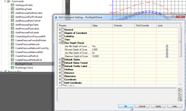
Figure 13.95 Edit the RunDepthCheck command settings to validate your design.
Also in the command settings you will find a separate listing for RunDesignCheck. Double-click (or right-click and click Edit) to enter these settings. You can set an acceptable range of values for pipe bends and radius of curvature for curved pipes. The Deflection Validation settings are found under RunDesignCheck, as shown in Figure 13.96.
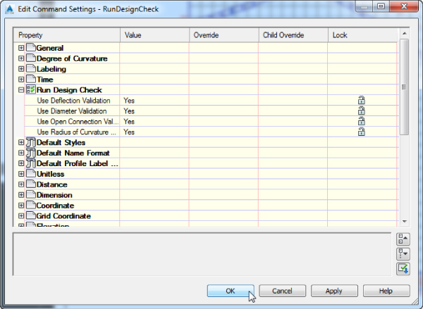
Figure 13.96 Turning on the Deflection Validation settings
Once you have created your pressure network, you should check your initial design for flaws. From the Pressure Networks contextual tab, you can check your design to see if it meets the requirements you set up in the command settings.
![]() Depth Check verifies that all pipes and fittings are within the acceptable range of values for depth.
Depth Check verifies that all pipes and fittings are within the acceptable range of values for depth.
![]() Design Check will check for improperly terminating pipes, mismatched pipe and fitting diameters, any curved pipe whose radius has exceeded acceptable values, and pipes that have exceeded the maximum deflection you set up in the parts list.
Design Check will check for improperly terminating pipes, mismatched pipe and fitting diameters, any curved pipe whose radius has exceeded acceptable values, and pipes that have exceeded the maximum deflection you set up in the parts list.
In the following exercise, you will modify the command settings and run a depth check on the pipe network:
- Open the
1312_DesignCheck.dwg(1312_DesignCheck_METRIC.dwg) drawing, which you can download from this book's web page. - In the Settings tab of Toolspace, expand Pressure Network Commands, right-click RunDepthCheck, and select Edit Command Settings (you could also double-click the command to access it).
- Expand the Run Depth Check category and verify that Minimum Depth Of Cover is set to 6′ (2 m).
- Click in the Value column and change Use Max Depth Of Cover Validation to Yes.
- Click OK.
- Select a pressure network part if you do not already see the Pressure Networks contextual tab.
- From the Pressure Networks contextual tab Analyze panel, select Depth Check.
- The Depth Check command will allow you to perform the analysis in either plan or profile view. Either way you choose to select your pressure pipe network, the result will be the same.
- At the
Select a path along a Pressure Network in plan or profile view:prompt, click the first pressure network object to the left in the profile view. - At the
Select next point on path [Enter to finish]:prompt, select the Gate Valve to the far right in the profile view and press ↵. - The Run Depth Check dialog will appear. The settings should be the same values as those in steps 3 and 4.
- Click OK.
- In both plan view (Figure 13.97, top) and profile view (Figure 13.97, bottom), warnings will appear if any Depth Check violations are found.
Figure 13.97 Depth Check result in plan (top) and profile : (bottom) views
- Save and close the drawing.
For your reference, completed versions of the drawing (1312_DesignCheck_FINISHED.dwg and 1312_DesignCheck_METRIC_FINISHED.dwg) are available with the rest of this book's download.
Understanding Part Builder
Part Builder is an interface that allows you to build and modify pipe network parts for gravity systems. You access Part Builder by selecting the Create Design drop-down from the Home tab. At first, you may use Part Builder to add a few missing pipes or structure sizes. As you become more familiar with the environment, you can build your own custom parts from scratch.
Parts created by Part Builder will not be available for use in pressure networks, so this section applies only to parts needed for gravity systems.
This section is intended to be an introduction to Part Builder and a primer in some basic skills required to navigate the interface. It isn't intended to be a robust “how-to” for creating custom parts. Civil 3D includes three detailed tutorials for creating three types of custom structures. The tutorials lead you through creating a cylindrical manhole structure, a drop inlet manhole structure, and a vault structure. You can find these tutorials by going to Help ![]() Tutorials and then navigating to Part Builder Tutorials.
Tutorials and then navigating to Part Builder Tutorials.
The parts in the Civil 3D pipe network catalogs are parametric. Parametric parts are dynamically sized according to a set of variables, or parameters. In practice, this means you can create one part and use it in multiple situations.
You can create one parametric model that understands how the different dimensions of the pipe are related to each other and what sizes are allowable. When a pipe is placed in a drawing, you can change its size. The pipe will understand how that change in size affects all the other pipe dimensions such as wall thickness, outer diameter, and more; you don't have to sort through a long list of individual pipe definitions.
Part Builder Orientation
Each drawing “remembers” which part catalog it is associated with. If you're in a metric drawing, you need to make sure the catalog is mapped to metric pipes and structures, whereas if you're in an Imperial drawing, you'll want the Imperial catalog. By default, the Civil 3D templates should be appropriately mapped, but it's worth the time to check. Set the catalog by changing to the Home tab and selecting the drop-down on the Create Design panel. Verify the appropriate folder and catalog for your drawing units in the Pipe Network Catalog Settings dialog (see Figure 13.98), and you're ready to go.
Figure 13.98 Choose the appropriate folder and catalog for your drawing units.
Understanding the Organization of Part Builder
The vocabulary used in the Part Builder interface is different from the rest of Civil 3D, so we will first examine the basics.
 Open Part Builder by going to the Home tab
 ![]() Create Design panel and selecting the Part Builder icon from the drop-down.
Create Design panel and selecting the Part Builder icon from the drop-down.
The first screen that appears when you start Part Builder is Getting Started - Catalog Screen (see Figure 13.99).
Figure 13.99 The Getting Started - Catalog Screen dialog
At the top of this window is a drop-down for selecting the part catalog type. Depending on what you need to modify, you can set this to either Pipe or Structure. Once you pick the catalog type, you will see the main catalog name. In Figure 13.99, you see US Imperial Pipe Catalog.
Below the part catalog is a list of part categories. In Part Builder vocabulary, a part or structure category is a grouping based on the shape for pipes and function for structures. Inside the category, you will see the part families listed. The US Imperial Pipe Catalog has four default chapters:
- Circular Pipes
- Egg-Shaped Pipes
- Elliptical Pipes
- Rectangular Pipes
You can create new chapters for different-shaped pipes, such as Arch Pipes.
The US Imperial Structure Catalog also has four default chapters: Inlets-Outlets, Junction Structures With Frames, Junction Structures Without Frames, and Simple Shapes. You can create new chapters for custom structures. You can expand each chapter folder to reveal one or more part families. For example, the US Imperial Circular Pipes chapter has six default families:
- Concrete Pipe
- Corrugated HDPE Pipe
- Corrugated Metal Pipe
- Ductile Iron Pipe
- HDPE Pipe
- PVC Pipe
Pipes that reside in the same family typically have the same parametric behavior, with differences only in size.
As Table 13.1 shows, a series of buttons on the Getting Started - Catalog Screen dialog lets you perform various edits to chapters, families, and the catalog as a whole.
Table 13.1 The Part Builder catalog tools
| Icon | Function |
| The New Parametric Part button creates a new part family. | |
| The Modify Part Sizes button allows you to edit the parameters for the selected part family. | |
| The Catalog Regen button refreshes all the supporting files in the catalog when you've finished making edits to the catalog. | |
| The Catalog Test button validates the parts in the catalog when you've finished making edits to the catalog. | |
| The New Chapter button creates a new chapter. | |
| The Delete button deletes a part family. Use this button with caution, and remember that if you accidentally delete a part family, you can restore your backup catalog as mentioned in the beginning of this section. |
Exploring Part Families
The best way to become oriented to the Part Builder interface is to explore one of the standard part families:
- Open Part Builder, and then in the Getting Started - Catalog Screen dialog, click the Part Catalog drop-down and select Pipe.
 Expanding the US Imperial Pipe Catalog Circular Pipe family, select Concrete Pipe (Concrete Pipe SI for metric users), and click the Modify Part Sizes button.
- It is not unusual to receive a message stating that the file contains previous version AEC objects. If you get such a message, click Close to continue.
- A Part Builder pane will appear with
AeccCircularConcretePipe_Imperial.dwg(AeccCircularConcretePipe_Metric.dwgfor metric users) on the screen, along with the Content Builder Toolspace, as shown in Figure 13.100.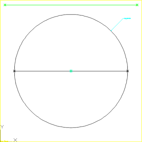
Figure 13.100 DWG file as shown in Content Builder
- Close Part Builder by clicking the X on the Part Builder pane.
- Click No when asked to save the changes to the concrete pipe.
- Click No when asked to save the drawing.
The Part Builder pane, or Content Builder (Figure 13.101), is well documented through the Autodesk Knowledge Network available for the Autodesk AutoCAD Civil 3D.
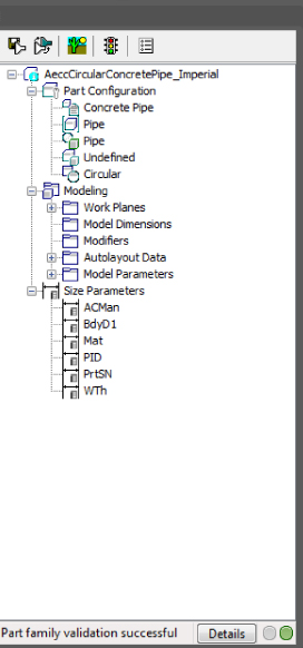
Figure 13.101 Content Builder
Adding a Part Size Using Part Builder
The hypothetical municipality requires a 12″ (300 mm) waste water cleanout. After studying the catalog, you decide that Concentric Cylindrical Structure NF (SI for metric users) is the appropriate shape for your model, but the smallest inner diameter size in the catalog is 48″ (1,200 mm). The following exercise gives you some practice in adding a structure size to the catalog—in this case, adding a 12″ (300 mm) structure to the US Imperial Structures catalog (Metric Structures Catalog for metric users).
You can make changes to the US Imperial Structures catalog from any drawing that is mapped to that catalog, which is probably any Imperial drawing you have open, as follows:
- For this exercise, start a new drawing from
_AutoCAD Civil 3D (Imperial) NCS.dwt(_AutoCAD Civil 3D (Metric) NCS.dwt). - On the Home tab, select the drop-down on the Create Design panel and select Part Builder.
- In the Getting Started - Catalog Screen dialog, choose Structure from the drop-down in the Part Catalog selection box.
- Expand the Junction Structures Without Frames category.
- Highlight the Concentric Cylindrical Structure NF (SI for metric users) part family.
- Click the Modify Part Sizes button.
The Part Builder interface opens
AeccStructConcentricCylinderNF_Imperial.dwg(AeccStructConcentricCylinderNF_Metric.dwgfor metric users) along with the Content Builder pane. - Zoom extents if necessary.
- In the Context Builder pane, expand the Size Parameters branch.
- Right-click the SID (Structure Inner Diameter) parameter, and choose Edit.
The Edit Part Sizes dialog appears.
- Locate the SID column (see Figure 13.102), and double-click inside the box.
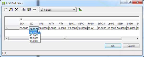
Figure 13.102 Examining the available part sizes
Note that a drop-down shows the available inner diameter sizes 48″, 60″, 72″, and 96″ (1,200 mm, 1,400 mm, 1,600 mm, and 1,800 mm).
 Locate the Edit button. Make sure you're still active in the SID column cell, and then click Edit.
The Edit Values dialog appears.
- In the Edit Values dialog, click Add and type 12 (metric users type 300), as shown in Figure 13.103.
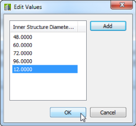
Figure 13.103 Add the 12″ (300 mm) value to the Edit Values dialog.
- Click OK to close the Edit Values dialog, and click OK again to close the Edit Part Sizes dialog.
- Click the small X in the upper-right corner of the Content Builder pane to exit Part Builder. If you don't see it, hover over the window top bar and it should be available.
- The message “Save Changes To Concentric Cylindrical Structure NF?” will appear. Click Yes.
You could also click Save in Content Builder to save the part and remain active in the Part Builder interface.
You're back in your original drawing. If you created a new parts list in any drawing that references the US Imperial Structures catalog (Metric Structures Catalog for metric users), the 12″ (300 mm) structure will be available for selection.
Sharing a Custom Part
You may need to go beyond adding pipe and structure sizes to your catalog and build custom part families or even whole custom chapters. Perhaps instead of building them yourself, you'll be able to acquire them from an outside source.
The following section can be used as a reference for adding a custom part to your catalog from an outside source, as well as sharing custom parts that you've created. The key to sharing a part is to locate three files that Civil 3D needs in order to use that part.
Adding a custom part size to your catalog requires these steps:
- Locate the
partname.dwg,partname.xml, and (optionally)partname.bmpfiles of the part you'd like to obtain. - Make a copy of the
partname.dwg,partname.xml, and (optionally)partname.bmpfiles. - Insert the
partname.dwg,partname.xml, and (optionally)partname.bmpfiles in the correct folder of your catalog. - Run the
PARTCATALOGREGENcommand in Civil 3D and select the specific catalog you need to regen. - If you added both structures and pipes, within the same command you can regen both pipes and structures. You may get errors on adding new parts from outside sources. Your best resources on this matter will be the Autodesk Knowledge Network for Civil 3D or the Autodesk Community forums.
Adding an Arch Pipe to Your Part Catalog
This exercise will teach you how to add a premade custom part to your catalog. You can make changes to the US Imperial Pipes (Metric Pipes for metric users) catalog from any drawing that is mapped to that catalog, which is probably any Imperial (metric) drawing you have open.
- For this exercise, start a new drawing from the
_AutoCAD Civil 3D (Imperial) NCS.dwtfile (_AutoCAD Civil 3D (Metric) NCS.dwt). - In Windows Explorer, create a new folder called
Arch Pipesin yourPipes Catalogdirectory. - For the purposes of the exercise, you should add the new pipe files into this directory. Remember, the real path is located here:
C:ProgramDataAutodeskC3D 2015enuPipes CatalogUS Imperial Pipes
(C:ProgramDataAutodeskC3D 2015enuPipes CatalogMetric Pipes)
This directory should now include five folders:
Arch Pipes,Circular Pipes,Egg-Shaped Pipes,Elliptical Pipes, andRectangular Pipes. - Copy the
Concrete Arch Pipe.dwg(Concrete Arch Pipe_METRIC.dwg),Concrete Arch Pipe.bmp(Concrete Arch Pipe_METRIC.bmp), andConcrete Arch Pipe.xml(Concrete Arch Pipe_METRIC.xml) files into theArch Pipesfolder. - Return to your drawing, and enter
PARTCATALOGREGENat the command line. - Type
Pand press ↵ to regenerate the Pipe catalog, and then press ↵ again to exit the command.If you created a new parts list or edited an existing one at this point in any drawing that references the US Imperial Pipes catalog, the arch pipe would be available for selection.
- To confirm the addition of the new pipe shape to the catalog, locate, open, and browse the catalog HTM file found at
C:ProgramDataAutodeskC3D 2015enuPipes CatalogUS Imperial
PipesImperial Pipes.htm
(C:ProgramDataAutodeskC3D 2015enuPipes CatalogMetric PipesMetric Pipes.htm)
The Bottom Line
- Create a pipe network by layout. After you've created a parts list for your pipe network, the first step toward finalizing the design is to use Pipe Network By Layout.
- Master It Open the
MasterIt_1301.dwgorMasterIt_1301_METRIC.dwgfile. Use Network Creation Tools to create a waste water pipe network named Mastering. Use the Composite surface, and name only structure and pipe label styles. Don't choose an alignment at this time. Create 8″ (200 mm) PVC pipes and a manhole called SMH. There are blocks in the drawing to assist you in placing manholes. Begin at the START HERE marker, and place a manhole at each marker location. You can erase the markers when you've finished.
- Master It Open the
- Create an alignment from network parts and draw parts in profile view. Once your pipe network has been created in plan view, you'll typically add the parts to a profile view based on either the road centerline or the pipe centerline.
- Master It Continue working in the
MasterIt_1301.dwgorMasterIt_1301_METRIC.dwgfile. You need to have completed the previous exercise before beginning this one. Create an alignment named Mastering from your pipes so that station zero is located at the START HERE structure. Create a profile view from this alignment, and show the pipes and profiles for the EG and Corridor FG surfaces on the profile view. Use defaults for everything, except change the Corridor FG profile style to FG Profile on the profile view.
- Master It Continue working in the
- Label a pipe network in plan and profile. Designing your pipe network is only half of the process. Engineering plans must be properly annotated.
- Master It Continue working in the
MasterIt_1301.dwgorMasterIt_1301_METRIC.dwgfile. You need to have completed the previous exercise before beginning this one. Add the Length Description And Slope pipe label style to profile pipes and the Data With Connected Pipes (Sanitary) structure label style to profile structures. Assign the alignment created in the previous “Master It” exercise to all pipes and structures.
- Master It Continue working in the
- Create a dynamic pipe table. It's common for municipalities and contractors to request a pipe or structure table for cost estimates or to make it easier to understand a busy plan.
- Master It Continue working in the
MasterIt_1301.dwgorMasterIt_1301_METRIC.dwgfile. You need to have completed the previous exercise before beginning this one. Create a pipe table for all pipes in your network. Use the default table style.
- Master It Continue working in the