
Chapter 18
Label Styles
The creation of proper styles and settings can make or break your experience with Autodesk® AutoCAD® Civil 3D® software. Styles control the display properties of Civil 3D objects and labels. Understanding and applying styles correctly can mean the difference between getting a job out in several hours and fighting with your project drawing for days.
This chapter is organized by style type. First, read the chapter to be introduced to the style concepts in a logical manner. Later, when you use this chapter as a reference to build styles, you will likely jump around to the examples that meet your needs.
In this chapter, you will learn to
- Override individual labels with other styles
- Create a new label set for alignments
- Create and use expressions
- Apply a standard label set to profiles
Label Styles
The best design in the universe is not worth anything unless it is labeled properly. Civil 3D labels are smart objects that are dynamically linked to the object they are labeling. Civil 3D labeling is customizable to fit your design needs and local requirements.
When talking about labels in Civil 3D, keep in mind that you are not just talking about text. Labels can contain lines and blocks if desired. Label styles control the plotted height, contents, and precision of text. They also control how leaders are applied when the label is dragged away from its initial position. You will even work with some labels that contain no text at all!
General Labels
![]() On the Settings tab, you'll see a complete list of objects that Civil 3D uses to build its design model. Each of them has special features unique to the object being described, but there are some common features as well. The General collection contains settings and styles that are applied to various objects across the entire product.
On the Settings tab, you'll see a complete list of objects that Civil 3D uses to build its design model. Each of them has special features unique to the object being described, but there are some common features as well. The General collection contains settings and styles that are applied to various objects across the entire product.
The General collection serves as the catchall for styles that apply to multiple objects and for settings that apply to no objects. For instance, the Civil 3D General Note object doesn't really belong with the Surface or Pipe collections. It can be used to relate information about those objects, but because it can also relate to something like “Don't Dig Here!” or a northing-easting of an arbitrary location, it falls into the General category.
The Label Styles collection allows Civil 3D users to place general text notes or label single entities while still taking advantage of the flexibility and scaling properties. The various label styles shown in Figure 18.1 can give you some idea of their uses.
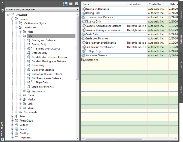
Figure 18.1 Line label styles
Label styles are a critical part of producing plans with Civil 3D. In this chapter, you'll learn how to build a new basic label and explore some of the common components that appear in every label style throughout the product.
Frequently Seen Tabs
To get into a label style, find the appropriate label type in the Settings tab of Toolspace. The Settings tab is organized into object collections. For each of the objects that can be labeled, the Label Styles branch will organize its labels based on their function, which makes it very easy to find the label style you need to edit. When you locate the desired label style, right-click the style to display Label Style menu options:
- Edit Opens the label style for modification.
- New Copies the label style as a child style, a style that inherits its settings from a parent.
- Copy Creates a duplicate label style.
- Delete Erases the label style. Visible only if the style is not is use.
- Find References Visible only if label style is in use. Searches settings and objects and lists where label styles are in use. The result of the search is displayed in a References dialog box.
- Replace With Visible only if label style is in use. Finds a label style in use in the drawing and replaces it with another.
All styles, regardless of type, have a few things in common:
- Information Tab The Information tab, shown in Figure 18.2, controls the name of the style.
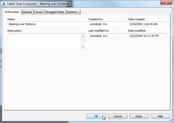
Figure 18.2 The Information tab exists for all object and label styles.
If desired, you can create a description. This information will appear as a tooltip as you browse through the Settings tab.
On the right side of the dialog, you will see the name of the person who originally created the style, the date when it was created, and the last person who modified the style. These names are initially pulled from the Windows login information, and only the Created By field can be edited.
- General Tab The General tab (Figure 18.13) contains basic settings for the label style and consists of the following:
- Text Style This option refers to the AutoCAD text style used in the label. Text styles must already be created in the drawing.
- Label Visibility This option allows the label to be not shown even if applied.
- Display Mode Allows a label to be displayed either in a Label mode or Tag mode. This setting is available only for specific object types including lines, curves, parcels, and alignments.
- Layer In Chapter 1, “The Basics,” you learned that the Object Layer tab in the Drawing Settings dialog is where you configure insertion layers for object types, labels, and tables. Freezing an object layer will, of course, make any object contained on that layer disappear. The Layer setting here on the General tab allows you to specify a layer that will override the layer properties of the object layer and also add another layer for controlling visibility of specific label types. For example, the object layer for alignment labels could be set to C-ALIGN-LABL. However, Major Station label styles could be configured to place the label on C-ROAD-STAN-MAJR. When C-ALIGN-LABL is frozen, all alignment labels disappear. When C-ROAD-STAN-MAJR is frozen, only Major Station labels disappear. If this setting is left set to layer 0, then the label using this style will default to the object layer display properties.
- Orientation Reference This option controls how text rotation is controlled. Figure 18.3a shows the label aligned with the object. Figure 18.3b shows the text rotated to the view. Even though the view has been rotated, the text still appears parallel with the bottom of the screen. The last, and least used, option for orientation reference is the World Coordinate System option, which is shown in Figure 18.3c. The view is rotated, and the direction of the text rotates with the World Coordinate System.
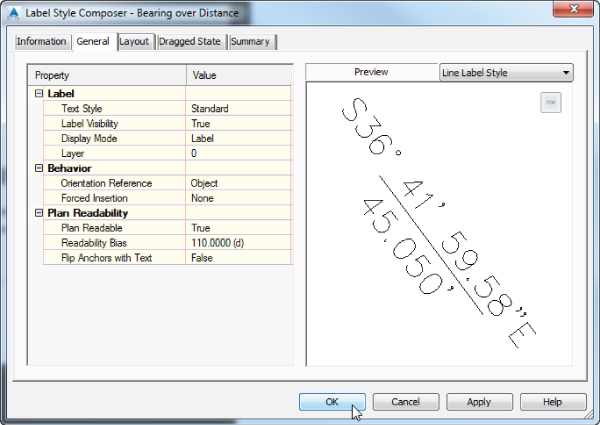
Figure 18.3 Orientation reference options set to Object (a), View (b), and World Coordinate System (c)
- Forced Insertion This option makes more sense in other objects and will be explored further. The Forced Insertion feature allows you to dictate the insertion point of a label on the basis of the object being labeled. Figure 18.4 shows the effects of the various options on a bearing and distance label.
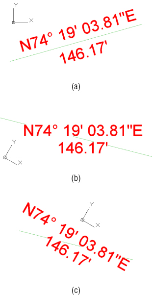
Figure 18.4 Forced Insertion options for parcel segments
- Plan Readable When this option is enabled, text maintains the up direction in spite of view rotation. Rotating 100 labels is a tedious, thankless task, and this option handles it automatically.
- Readability Bias This option specifies the angle at which readability kicks in. This angle is measured from the 0 degree of the x-axis that is common to AutoCAD angle measurements. When a piece of text goes past the readable bias angle, the text flips 180 degrees to maintain vertical orientation, as shown in Figure 18.5. The default Readability angle is 110. A common desired default is 90.1, which would flip any text just after passing a vertical direction.
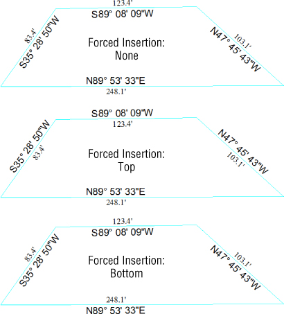
Figure 18.5 Plan-readable text shown on contours; note the difference in direction for the true and false settings (PR = Plan Readable).
- Flip Anchors With Text Most users leave this setting at its default, False, and never give it another thought. Figure 18.6a shows what happens to the text insertion points when this option is set to False and readability kicks in. The SW bearing is followed by its distance as originally configured. Readability has been applied to the NW bearing because it was configured to be oriented to the object it is labeling. Without readability, the label would be upside down. Distance and bearing have been flipped individually so it appears the two values are out of order. When this setting is set to True, the distance text flips to the other side of the bearing, as shown in Figure 18.6b. You'll have the opportunity to work with this setting in a later exercise.
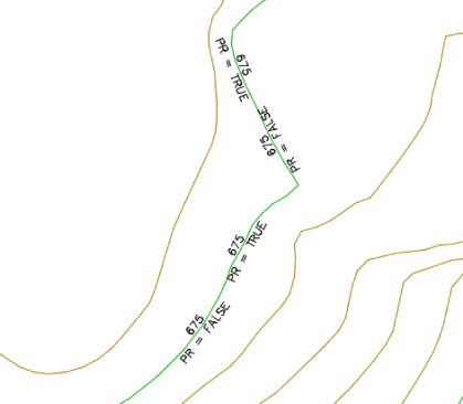
Figure 18.6 Flip Anchors With Text when readability kicks in: set to False (a); set to True (b)
- Layout Tab Each label can be made up of several components. A Label component can be text, a block, or a line. Depending on the type of label style, other options can include Reference Text, Ticks (station labels), Direction Arrow (line labels), or Text For Each (structure styles only). The top row of buttons controls the selection, creation, and deletion of these components, as shown in Figure 18.7.
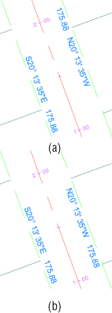
Figure 18.7 The Layout tab
 Component NameFrom the Component Name drop-down, choose the component you want to modify. The components are listed in the order in which they were created. When you make changes to properties on the Layout tab, pay attention to which component is active. Any changes you make to the properties will apply only to the active : component. It is important to note that in the label's dragged state the displayed order reflects the order in which the components were created.
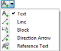 Create Component The Create Component button lets you add new components to : enhance your labels. A component can be Text, Line, Block, Tick, Direction Arrow, Reference Text, or Text For Each. The options will vary depending on the object you are labeling. Not every option is available in every label. For example, Text For Each is available only in structure labels.
The ability to label one object while referencing another (reference text) is one of the most powerful labeling features of Civil 3D. This is what allows you to label a spot elevation for both an existing and a proposed surface at the same time, using the same label. Alignments, COGO points, parcels, profiles, surfaces, and survey figures can all be used as reference text. Text For Each is a type of component that can label properties of connected pipes in a structure label.
 Copy Component The Copy Component button copies the component currently selected in the Component Name drop-down. This will be helpful when you're creating label styles that contain multiple pieces of similar information.
 Delete Component The Delete Component button deletes components. Components that are configured as anchors for other components can be deleted, but you will receive a warning. Table tag components, found in curve, line, alignment segment, and parcel segment labels, cannot be deleted.
 Component Draw Order The Component Draw Order button lets you shuffle components up and down within the label. This feature is especially important when you're using masks or borders as part of the label.
Once a component is added, the component properties can be addressed one by one by starting at the top and working your way down to the bottom of the dialog. There are three groups of property types: General, Text, and Border.
The General properties consist of the following:
- Name This option defines the name used in the Component Name drop-down and when selecting other components for anchor components. Once a component is configured as an anchor component, the name cannot be changed until the reference is removed. When you're building complicated labels, a descriptive name goes a long way.
- Visibility When this option is set to True, the component can be seen onscreen. When a component can't be seen, you can do some cool tricks with styles, as you'll see in the “Pipe Labels” section later in this chapter.
- Used In Available for labels of specific elements such as lines, curves, parcels, and alignments. The component can be assigned to be displayed in either Label or Tag mode.
- Anchor Component This setting allows you to position the component relative to the feature being labeled or to another component.
- Anchor Point The options here may vary depending on the Anchor Component setting. When the feature is being used as an Anchor component, the anchor point can be a location relative to the feature offering combinations of middle, top, and bottom vertical positions with left, right, and center horizontal positions. Line components offer start, middle, and end anchor points. Also note that for specific elements like points, pipes, and structures, there is an option to set the anchor point to the element's dimension (see the Attachment property on the Layout tab for more on anchor points).
The settings available for label layout under the Layout tab of the Label Style Composer dialog are displayed in Figure 18.8.
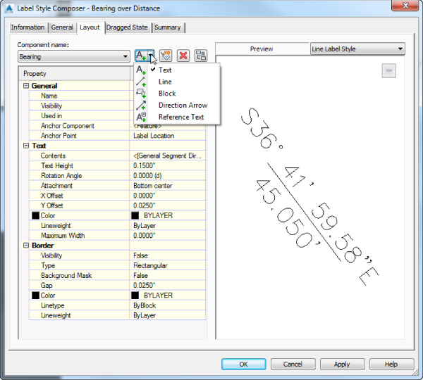
Figure 18.8 The circle and square indicate the places where the anchor point and attachment point are defined.
The Text properties consist of the following:
- Contents This is where the information contained in the label is composed. Click the Value field to reveal an ellipsis. If the ellipsis is clicked, the Label Style Composer dialog opens to where property fields and text can be configured. Also under Contents you can find a Format tab that allows you to apply text justification and override the font used in the style among others.
- Text Height This option determines the plotted height of the label. This setting overrides the height configured in the text style. Regardless of how the text style is configured in the label, text placed by Civil 3D is always annotative. The two viewports in Figure 18.9 show some COGO points along a road. Even when the viewport scales differ, the text is the same size. For a block component this setting will be called Block Height, while for a line component this will be the Line Length.
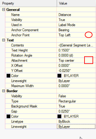
Figure 18.9 Annotative text shown at multiple scales
- Rotation Angle, X Offset, and Y Offset These options give you the ability to adjust the placement of the component by rotating or displacing the text in an x or y direction. Set your text as close as possible using the anchors and attachments, and use the offsets as additional spacing. If border gap is used, this will affect spacing as well.
- Attachment This option determines which of the nine points on the Label Components bounding box are attached to the anchor point. Figure 18.8 defines the place where this setting can be changed, while Figure 18.10 illustrates the relationship between the anchor points and attachments.
Figure 18.10 Schematic showing the relationship between anchor points (circles) and attachments (squares)
- Color and Lineweight These options allow you to override the color and lineweight assigned by the layer configured on the General tab.
- Maximum Width Some labels can be rather lengthy. Instead of letting the Label component continue indefinitely across the page, you can use Maximum Width to force word wrap after a specified plotted length. The default setting of 0.00 will not force word wrap.
The Border properties consist of the following:
- Visibility Use this option to turn the border on and off for the component. Remember that component borders shrink to the individual component; if you're using multiple components in a label, each will have its own Border component.
- Type This option allows you to select a rectangle, a rounded rectangle (slot), or a circle border. Figure 18.11 shows examples of the three types of borders.
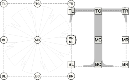
Figure 18.11 Border types shown on various surface label styles
- Background Mask This option lets you determine whether linework and text behind this component are masked. This option can be handy for construction notes in place of the usual wipeout tools. The surface labels in Figure 18.11 show the background mask in action.
- Gap This option determines the offset from the Component bounding box to the outer points on the border. Setting this to half of the text size usually creates a visually pleasing border.
- Color, Linetype, and Lineweight These options allow you to override the display properties assigned by the layer configured on the General tab.
- Dragged State Tab Typically, dragging a label in Civil 3D creates a leader and rearranges the text. The settings that control these two actions appear on this tab (see Figure 18.12).
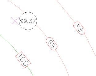
Figure 18.12 The Dragged State tab
Many of the property types found on this tab appeared on the Layout tab, so they don't need to be defined again. There are two groups of property types: Leader and Dragged State Components.
Settings found in the Leader properties sections include the following:
- Arrow Head Style This allows you to set the appearance of the leader. The same Arrow Head styles that appear in Dimension styles are available in Dragged State.
- Arrow Head Size This setting controls the length of the arrow head as well as the length of the landing leading to the text object.
- Type This option specifies the leader type. The options are Straight Leader and Spline Leader. Civil 3D labels can have only one leader.
Settings found in the Dragged State Component properties include the following:
- Display In this option, you can choose Stacked Text or As Composed. The Stacked Text option will remove any blocks, ticks, lines, dimensions, or borders that are components of the label, and it will stack the Text components as a list in the order in which they were created, realign the text to horizontal, and justify based on the direction you drag. The As Composed option leaves blocks, ticks, lines, text, dimensions, or borders intact, and it adds a leader next to the attached component that is anchored to the feature.
- Text Height Text Height was mentioned for the previous setting. However, there is a separate setting for Text Height when in dragged state and the label style Display property is configured to Stacked Text.
- Leader Attachment When the label style Display property is configured to Stacked Text, this property sets the location of the landing relative to the top line, bottom line, or middle of the stacked text.
- Leader Justification When the label style Display property is configured to Stacked Text, this property determines if and how text is justified. When set to True and the leader is to the left of the text, the text will be left justified; when set to True and the leader is to the right of the text, the text will be right justified. When set to False, the leader is always left justified.
- Maximum Text Width This property works in the same way as Maximum Width on the Layout tab.
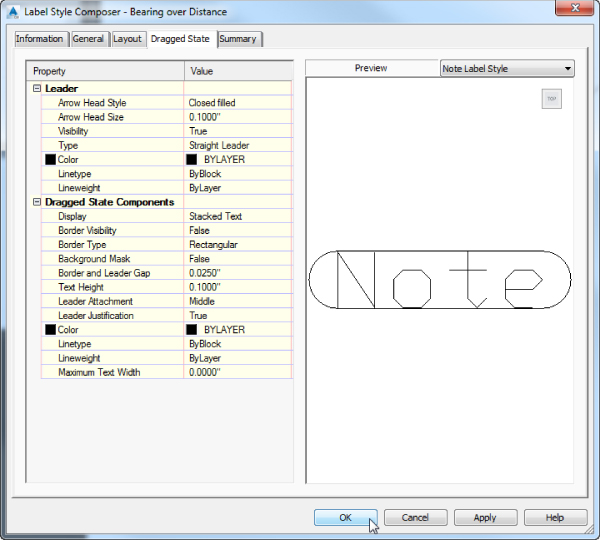
Figure 18.13 The General tab
Figure 18.15a shows an alignment label as it was originally placed. Figure 18.15b shows the same label in a dragged state with the Stacked Text option set. Figure 18.15c shows the label in a dragged state with the As Composed option set.
- Summary Tab The Summary tab is exactly what it sounds like—that is, a summary of all other settings that exist in the style. The information from other tabs in list form, as well as their override status, is shown in Figure 18.14.
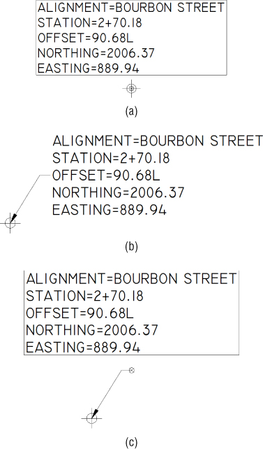
Figure 18.14 The Summary tab of a label style
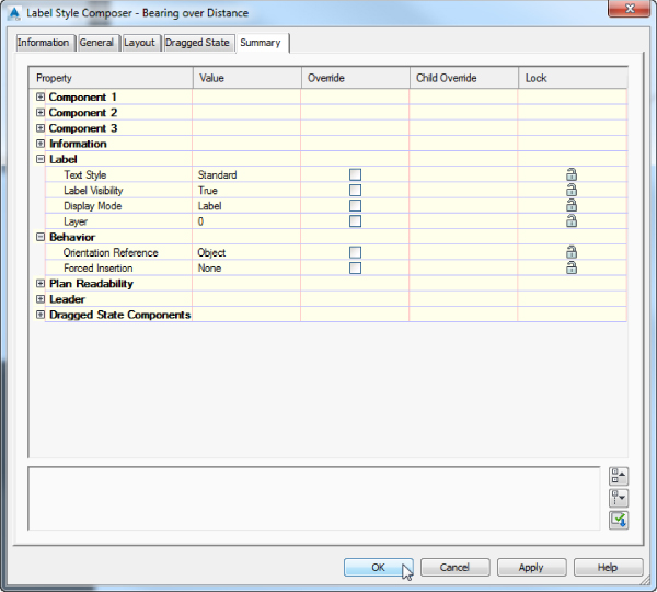
Figure 18.15 An alignment label as originally placed (a); dragged state, Stacked Text (b); and dragged state, As Composed (c)
![]() As with other settings in Civil 3D, a hierarchy helps determine which styles take precedence over other styles. There are also defaults that can be set or changed at a drawing-wide level and overridden at an object level. Make sure to put some thought into using these hierarchical settings and relationships. By using them efficiently, you can save a lot of time because you won't need to tweak every setting in each label you create—and you will be creating many labels.
As with other settings in Civil 3D, a hierarchy helps determine which styles take precedence over other styles. There are also defaults that can be set or changed at a drawing-wide level and overridden at an object level. Make sure to put some thought into using these hierarchical settings and relationships. By using them efficiently, you can save a lot of time because you won't need to tweak every setting in each label you create—and you will be creating many labels.
In this first exercise, you will set all the labels to use the same initial text style:
- Open the drawing
1801_LabelBasics.dwg(1801_LabelBasics_METRIC.dwg), which you can download from this book's web page at www.sybex.com/go/masteringcivil3d2015. - From the Settings tab of Toolspace, right-click the name of the drawing and select Edit Label Style Defaults, as shown in Figure 18.16.
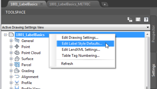
Figure 18.16 Accessing the global label settings
- Expand the Label category and, clicking within the cell and the ellipsis button, change Text Style to Arial. Click OK.
- Click the arrow in the Child Override column to force all the label styles in this drawing to use the same text style, as shown in Figure 18.17.
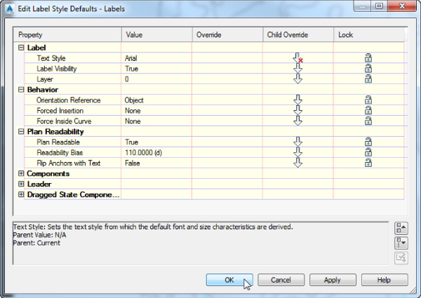
Figure 18.17 The label placement options at the drawing level. Note the Child Override arrow with a red X, which means that this change will be applied to all existing styles in the drawing.
- Do not make any more changes to this dialog. Examine the various options and settings, and click OK.
- Keep the drawing open for the next exercise.
General Note Labels
General Note labels are versatile, non-object-specific labels that can be placed anywhere in the drawing. There are several advantages to using these instead of base AutoCAD Mtext. Notes will leader and scale the same as the rest of your Civil 3D labels—and best of all, they can contain reference text.
Continuing with the previous exercise, you'll create an alternative parcel label that contains reference text.
- Continue working in
1801_LabelBasics.dwg(1801_LabelBasics_METRIC.dwg). - From the Settings tab of Toolspace, choose General
 Label Styles Note.
 - Right-click Note and select New (as shown in Figure 18.18).
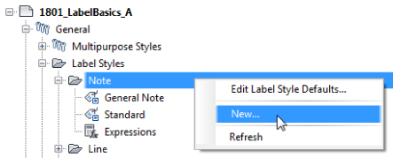
Figure 18.18 Creating your first new label style from the Settings tab
- On the Information tab, name the style Easement Parcel Text.
- On the General tab, set Layer to C-PROP-TEXT and set Orientation Reference to View.
- On the Layout tab, click the Value field next to Contents under the Text category.
Clicking this will cause an ellipsis button to appear.
- Click the ellipsis button to enter the Text Component Editor dialog.
- On the right side of the Text Component Editor dialog, delete the existing text and replace it with Drainage Easement, as shown in Figure 18.19. Click OK.
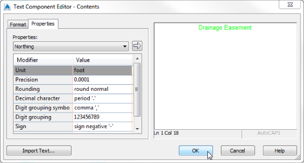
Figure 18.19 Entering the Text Component Editor dialog for basic text
- Back in the Layout tab, set Border Visibility to False.
 Click the flyout next to Create Text Component and select Reference Text.
You will be prompted to select the type of reference text, as shown in Figure 18.20.
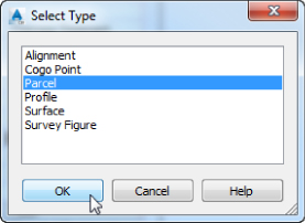
Figure 18.20 Picking the reference type
- In the Select Type dialog, select Parcel and click OK.
- Click in the Value field next to Name under the General category, rename Reference Text.1 to Parcel Area, and make the following changes.
- Set Anchor Component to Text.
- Set Anchor Point to Bottom Center.
- Set Attachment to Top Center.
- To enter the Text Component Editor dialog, click the Value field next to Contents and click the ellipsis.
- In the Text Component Editor dialog, delete the default label text.
- On the left side of the Text Component Editor dialog, do the following:
- Set the Properties drop-down to Parcel Area.
- Set Unit to Acre (Hectares for metric users).
- Set Precision to 0.01.
 When you have set the properties, click the arrow to place the text in the right side of the editor.
- Click to place your cursor after the previously inserted text and add a space. Type ACRES (or HECTARES for metric users) after the coding.
The Text Component Editor dialog will resemble Figure 18.21.
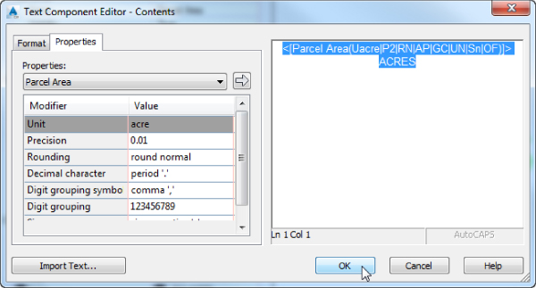
Figure 18.21 Adding “smart” text to the Text Component Editor dialog
- Click OK.
You will still have question marks in the preview, but this is completely as expected.
- Set the gap under the border to 0.05″ (2.00 mm for metric users). Click OK to complete the command.
- On the Annotate tab Labels & Tables panel, click the top half of the Add Labels button.
- With Feature and Label Type both set to Note, change Note Label Style to Easement Parcel Text, and click Add.
- At the
Pick Label Location:prompt, click anywhere in the example parcel. - At the
Select parcel for label style component Parcel Area:prompt, click the label on Property : 1. - Press Esc to finish placing the labels.
Your completed and placed label should resemble Figure 18.22.
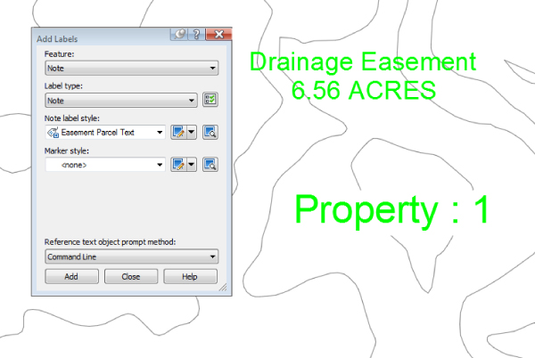
Figure 18.22 Your first label! Referencing a parcel area.
Save and close the drawing. A saved copy of this drawing, with the filename 1801_LabelBasics_FINISHED.dwg (1801_LabelBasics_METRIC_FINISHED.dwg), is available from the book's web page.
Point Label Styles
![]() If you have used other software packages for surveying work, odds are that you controlled the display of point label text with layers, but Civil 3D is different. In Civil 3D, you can control what information is showing next to a point by swapping the label style applied to a group of points.
If you have used other software packages for surveying work, odds are that you controlled the display of point label text with layers, but Civil 3D is different. In Civil 3D, you can control what information is showing next to a point by swapping the label style applied to a group of points.
In the following exercise, you will create a new point label style. Your first point label style will show only Point Number and Description, so you will need to delete the default Elevation component.
- Open the drawing
1802_PointLabels.dwg(1802_PointLabels_METRIC.dwg), which you can download from this book's web page. - From the Settings tab of Toolspace, expand Point Label Styles.
- Right-click Label Styles and select New.
- On the Information tab, name the style Point Number & Description.
- On the General tab, set the layer to V-NODE-TEXT, and leave all other General tab options at their defaults.
- On the Layout tab, do the following:
- Set the Active Component to Point Number.
- Change the Anchor Component to <Feature>.
- Set Anchor Point to Middle Right.
- Set Attachment to Middle Left.
- Change the Active Component to Point Elevation.
- Click the red X to delete this component.
You will receive a warning that reads “This label component is used as an anchor in this style or in a child style. Do you want to delete it?”
- Click Yes.
- Change the Active Component to Point Description.
- Change the Anchor Component to Point Number.
- Change the Anchor Point to Middle Right.
- Change the Attachment to Middle Left.
- Change the X Offset to 0.05” (1 mm for metric users).
- Click OK to complete the label style.
- On the Prospector tab of Toolspace, locate the point group named TOPO; right-click TOPO and select Properties.
- On the Information tab, set the Point Label Style to Point Number & Description.
- Click OK to close the Point Group.
All the points in the group will change to resemble Figure 18.23.
Figure 18.23 Completed point label style
In the previous exercise, you created a simple new label style and made some modifications to the default components. In the following exercise, you will remove all the default components and add Northing and Easting values to the label using the Text Component Editor dialog.
- Continue working in the drawing
1802_PointLabels.dwg(1802_PointLabels_METRIC.dwg). You need to have completed the previous exercise. - From the Settings tab of Toolspace, choose Point Label Styles.
- Right-click Label Styles, and select New.
- On the Information tab, name the style Northing & Easting.
- On the General tab, set the layer to V-NODE-TEXT, set the Orientation Reference to View, and leave all other General tab options at their defaults.
- On the Layout tab, do the following:
- Click the red X until all three default components are gone.
For the second component being deleted, you will receive a warning that reads “This label component is used as an anchor in this style or in a child style. Do you want to delete it?”
- Click Yes and delete the last component.
- Click the Create Text Component button to create a new Text component, and rename the component to N-E.
- Set the Anchor Point to Bottom Center.
- Set the Attachment to Top Center.
- Click the Value field next to Contents and click the ellipsis to enter the Text Component Editor dialog.
- Click the red X until all three default components are gone.
- In the Text Component Editor dialog, do the following:
- Highlight the default label text and delete it by pressing the Delete key on your keyboard.
- From the Properties list, select Northing.
- Set the Precision to 0.01 (two decimal places).
- Click the arrow to place the text to the right.
- Before the label text, place an N: as a static text. Move to the end of the line. Press the Enter key to move to the next line.
- From the Properties list, select Easting, and set the Precision to 0.01 (two decimal places).
- Click the arrow to place the text to the right.
- Before label text, place an E: as static text.
The Text Component Editor dialog will now resemble Figure 18.24.
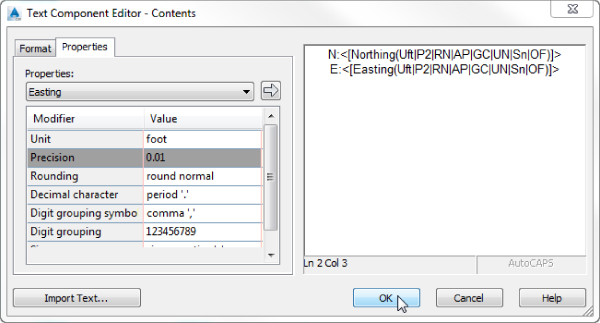
Figure 18.24 The Northing & Easting label in progress
- Click OK to dismiss the Text Component Editor dialog, and click OK to complete the style.
- On the Prospector tab of Toolspace, locate the point group named Group2; right-click it and select Properties.
- Set the Point Label Style to Northing & Easting, and then click OK.
The labels will resemble Figure 18.25.

Figure 18.25 Northing & Easting in the completed exercise
Save and close the drawing. A saved copy of this drawing, 1802_PointLabels_FINISHED.dwg (1802_PointLabels_METRIC_FINISHED.dwg), is available from the book's web page.
Line and Curve Labels
You can add bearing and distance labels to many Civil 3D objects. Anything from plain lines and polylines to parcels and alignment tangent segments can use nearly identical label types.
The examples in the following exercises will use parcels for labeling, but the tools can be applied to all other types of line labels.
Single Segment Labels
In the following exercise, you will create a new line label style that uses default components. You will remove the direction arrow and change the display precision of the direction component.
- Open the
1803_LineandCurveLabels.dwg(1803_LineandCurveLabels_METRIC.dwg) drawing file, which you can download from this book's web page. - From the Settings tab of Toolspace, expand Parcel Label Styles Line; right-click Line and select New.
- On the Information tab, name the style Parcel Segment.
- On the General tab, set the layer to C-PROP-LINE-TEXT.
Leave all other General tab options at their defaults.
- On the Layout tab, do the following:
- Change the Active Component to Direction Arrow, and click the red X to delete this component.
- Change the Active Component to Distance.
- Click the Value field next to Contents, and click the ellipsis to enter the Text Component Editor dialog.
- In the Text Component Editor dialog, do the following:
- Click the text to highlight the Segment Length contents on the right.
All of the text should highlight as a unit.
- On the left side of the Text Component Editor dialog, change the Precision value to 0.01.
- Click the arrow to update the text.
- Click OK to dismiss the Text Component Editor dialog, and click OK to complete the style.
- Click the text to highlight the Segment Length contents on the right.
- Select the Annotate tab Labels & Tables panel and click the top of the Add Labels button to add labels to the parcels. In the Add Labels dialog, do the following:
- Set Feature to Parcel.
- Set Label Type to Single Segment.
- Set Line Label Style to Parcel Segment.
- Click Add and select for labeling the segments from Parcels 2 and 3.
- Close the Add Labels dialog and press Esc.
The completed labels will resemble Figure 18.26.
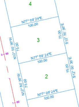
Figure 18.26 Your new bearing and distance line label style in action on parcel segments
Compare your drawing at this point against 1803_LineandCurveLabels_A.dwg (1803_LineandCurveLabels_A_METRIC.dwg) if needed.
Spanning Segment Labels
When you look at the labels you created in the previous exercise, you may notice that they stop at each parcel vertex. If there is a series of back lot lines that share the same bearing, most plats show this using a single label outside the overall property line displaying the bearing and the combined distance of these lot lines. To label this in Civil 3D, a separate label style is needed.
Spanning labels can be used in both line and curve parcel labels. In the following exercise, you will create line labels that span multiple parcel segments:
- Continue working in the finished drawing from the previous exercise or open
1803_LineandCurveLabels_A.dwg(1803_LineandCurveLabels_A_METRIC.dwg). - From the Settings tab of Toolspace, expand Parcel Label Styles Line, right-click Parcel Segment, and select Copy.
- On the Information tab, name the style Parcel Spanning Segment.
- On the General tab, under Plan Readability, change Readability Bias to 90.1 and change Flip Anchors With Text to True.
- On the Layout tab, do the following:
- Change the Active Component to Table Tag.
- Change the Span Outside Segments setting to True.
- Change the Active Component to Bearing.
- Change the Span Outside Segments setting to True.
- Change the Active Component name to Distance.
- Change the Anchor Component to Bearing.
- Change the Anchor Point to Bottom Right.
- Change the Span Outside Segments setting to True.
- Change Attachment Point to Bottom Left.
- Change X Offset to 0.2″ (3 mm for metric users) and make sure that Y Offset is set to 0.
- Click OK to complete the style.
- Using a technique similar to the one you used in the previous exercise, add a spanning label to the parcels along the east side of the right-of-way just north of Parcel 3. This time use Spanning Segment as the line label style. Your completed label will resemble Figure 18.27.
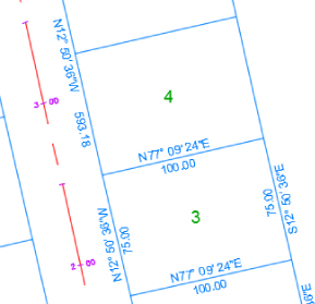
Figure 18.27 Spanning label shown on the outside of parcel segments
Compare your drawing at this point against
1803_LineandCurveLabels_B.dwg(1803_LineandCurveLabels_B_METRIC.dwg) if needed. When you place spanning labels on segments, the Distance component must be forced to the outside of the parcel line. You may need to use the Flip Label command on occasion to move the Distance component to the right location. To access the Flip Label command, select the label and then click the contextual tab Modify panel.
Curve Labels
In base AutoCAD, creating curve labels is a chore. If you want text to align to curved objects, you won't be able to use it as traditional Mtext. Luckily, Civil 3D gives you the ability to add curved text without compromising its usability.
In the following exercise, you will create a curve label style with a delta symbol (Δ) and text that curves with the parcel segment:
- Continue working in the finished drawing from the previous exercise or open
1803_LineandCurveLabels_B.dwg(1803_LineandCurveLabels_B_METRIC.dwg). You need to have completed the previous exercise to continue. - From the Settings tab of Toolspace, expand Parcels Label Styles Curve, right-click Curve, and select New.
- On the Information tab, rename the style to Delta Length & Radius.
- On the General tab, set Layer to C-PROP-LINE-TEXT.
- On the Layout tab, do the following:
- Change the Active Component to Distance And Radius.
- Click the Value field next to Contents and click the ellipsis to enter the Text Component Editor dialog.
- Highlight the segment length property on the right and change the precision to 0.01.
- Click the arrow to update the style.
- Highlight the Segment Radius property and change the precision to 0.01.
- Click the arrow to update the text.
- Delete the comma that appears as static text in the Text Component Editor dialog, and click OK.
- Click the Create Text Component button and do the following:
- Rename the new text component to Delta.
- Change Attachment to Bottom Center.
- Change the Y Offset to 0.025” (1 mm for metric users).
- Set Allow Curved Text to True.
- In the Contents field, click the ellipsis button to bring up the Text Component Editor dialog and do the following:
- Remove the default label text.
- Switch to the Format tab, click the Symbol button, and select Other.
You should now see the Character Map dialog (Figure 18.28).
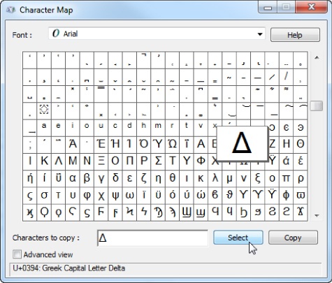
Figure 18.28 Browse for special symbols using the Windows character map.
- Browse through the symbols of the dialog to find the delta symbol; when you locate it, click the symbol, click the Select button, and then click Copy. Click the red X to close the Character Map dialog.
- Back in the Text Component Editor dialog, click the right side of the dialog, right-click, and select Paste.
- Press the Backspace key if the cursor jumps to the next line of text.
You should see the delta symbol appear in the Text Component Editor dialog.
- Enter the equal sign (=) as static text after the delta.
- Switch back to the Properties tab.
- From the Properties drop-down, select Segment Delta Angle, and do the following:
- Set the Format to DDºMM'SS.SS”.
- Set the Precision value to 1 Second.
- Click the arrow to place the text in the right side.
- Click OK to exit the Text Component Editor dialog.
- Click OK to complete the style.
- Add labels to Parcel 1 using the same technique you used in the previous exercise.
Remember to make sure that your style selection is set correctly for both the curve and line before adding labels.
- Set the active curve label style to Delta Length & Radius and add labels to some curves. If labels overlap, drag one of the labels by selecting it, and then pick the square-shaped grip and drag it to a new location.
When it is applied to the design, your completed label should resemble Figure 18.29.
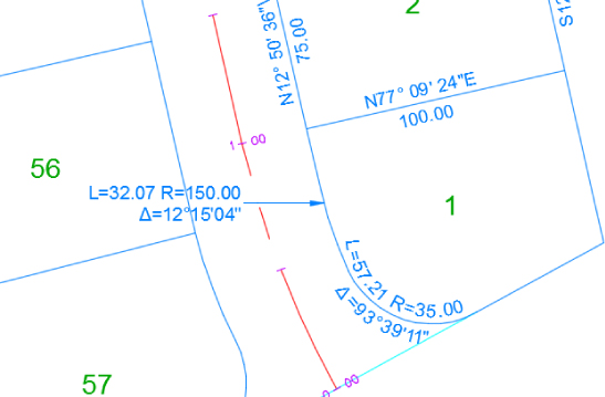
Figure 18.29 Completed curve labels with delta symbol and curved text
Save and close the drawing. A saved copy of this drawing, 1803_LineandCurveLabels_FINISHED.dwg (1803_LineandCurveLabels_METRIC_FINISHED.dwg), is available from the book's web page.
Pipe and Structure Labels
No two municipalities seem to label their pipes and sewer structures exactly the same way. Fortunately, Civil 3D offers a lot of flexibility in how you label these items.
Pipe Labels
Pipe labels have two separate label types: Plan Profile and Crossing Section. Both label types have many of the same options, but those options are used in different view directions.
In the following exercise, you will use a common trick. When a nonvisible component acts as an anchor to visible objects, you can use the flow direction arrow to force text to be placed at the ends and middle of the pipe regardless of the pipe length.
- Open the
1804_PipeandStructureLabels.dwg(1804_PipeandStructureLabels_METRIC.dwg) drawing file, which you can download from this book's web page. - From the Settings tab of Toolspace, choose Pipe Label Styles Plan Profile, and then right-click Plan Profile and select New.
- On the Information tab, name the style Length Diameter Slope.
- On the General tab, set the layer to C-STRM-TEXT.
- On the Layout tab, delete the existing Pipe Text component by clicking the red X.
 Expand the Create New Component drop-down and select Flow Direction Arrow; then adjust these settings:
- Set Visibility to False.
- Set Anchor Point to Top Outer Diameter.
- Set a Y offset of 0.1” (0.3 mm).
- Expand the Create New Component drop-down and select Text. Change these settings:
- Rename the Text Component to Length.
- Set Anchor Component to Flow Direction Arrow.1.
- Set Anchor Point to Start.
- Set Attachment to Bottom Left.
- In the Contents field, click the ellipsis button to bring up the Text Component Editor dialog and do the following:
- Delete the default label text.
- From the Properties list, set 2D Length – Center to Center current.
- Set Precision to 1 and Rounding to round up. This causes the pipe length value to round to the next-highest whole unit.
- Click the arrow to place the text in the editor.
- Add a foot symbol (or m for meters) after the text component.
- Click OK.
 With Length as the current component, click Copy Component. Then change these settings:
- Rename the component to Diameter.
- Change Anchor Point to Middle.
- Change Attachment to Bottom Center.
- Enter the Text Component Editor dialog and do the following:
- Delete all of the text.
- From the Properties list, select Inner Pipe Diameter.
- Set the Precision to 1 and click the arrow to add the text.
- Add the inch symbol (or mm for millimeters) after the Text component.
- Click OK to exit the Text Component Editor dialog.
- With Diameter as the current component, click Copy Component. Then change these settings:
- Rename the component to Slope.
- Set Anchor Point to End.
- Set Attachment to Bottom Right.
- Enter the Text Component Editor dialog and do the following:
- Delete all of the text.
- Set Pipe Slope as the current property.
- Click the arrow to add the text.
- Click OK to exit the Text Component Editor dialog.
- Click OK to complete the style.
- Add the label to the pipe by doing the following:
-
- On the Annotate tab Labels & Tables panel, click the top half of the Add Labels button.
- Set the Feature option to Pipe Network and Label Type to Single Part Plan.
- Set Pipe Label Style to Length Diameter Slope.
- Click Add. Select any pipe in plan view.
Your labeled pipe will resemble Figure 18.30.
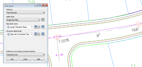
Figure 18.30 Use the invisible arrow trick to label pipe.
Compare your drawing at this point against
1804_PipeandStructureLabels_A.dwg(1804_PipeandStructureLabels_A_METRIC.dwg) if needed. - On the Annotate tab
Structure Labels
Structure labels are unique because they possess a special component that references information from each connected pipe, allowing you to place pipe properties in structure labels. Examples would be pipe invert, pipe direction (NE, SW, etc.), and flow direction (in or out).
Profile and Alignment Labels
Profile and alignment labels can take on many forms. On an alignment you may want to show station labels every 100′ (25 m) in addition to PC, PT, and PI information. On a profile, you will want tangent grades, curve information, and grade breaks.
Many types of label styles can be applied to an alignment and profile. Each type has a unique set of properties. Fortunately, these styles can be applied in sets to expedite labeling.
Label Sets
A label set is a grouping of labels that apply to the same object. In lieu of having one big style that accounts for multiple aspects of an object, the labels are broken out into specific types to allow you more control.
Label sets come into play with alignments and design profiles. When you look at an alignment or profile and see labels, you are usually seeing multiple label styles in action.
Consider the alignment shown in Figure 18.31. How many labels are on this alignment? The geometry points, the major stations, the minor ticks, superelevation critical points, and design speed are all different label types.
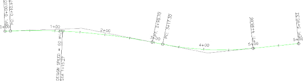
Figure 18.31 One alignment, five label styles in play
How did those labels get there? When you first created the alignment or profile, one of the options was to specify a label set (as shown in Figure 18.32a). All label types included in the label set by default are placed on the alignment at all locations where they can be applied with their associated style. Also after the creation you can select the alignment, and from the contextual tab you can add specific labels, as shown in Figure 18.32b.
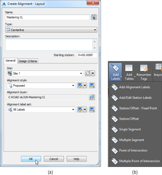
Figure 18.32 Specifying an alignment label set upon creation (a) and adding specific labels after alignment creation (b)
To edit which labels are applied to an alignment or profile, click one of the alignment labels, and from the Labels - Alignment Geometry Point Label Group contextual tab ![]() Modify panel, select Edit Label Group. Note that the contextual tab name will be different depending on which alignment label you choose.
Modify panel, select Edit Label Group. Note that the contextual tab name will be different depending on which alignment label you choose.
Label sets also control some aspects of the location of the annotation. An alignment label set controls the major and minor station labeling increment and the type of geometry points that are labeled. A profile label set can control whether labels are positioned with respect to the graph top or bottom edge or to the profile. Figure 18.33 shows the two columns, Dim Anchor Opt and Dim Anchor Val, where this positioning is configured.
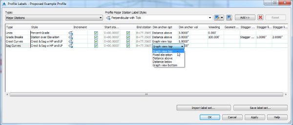
Figure 18.33 Profile labels and placement options
Alignment Labels
You'll create individual label styles over the next couple of exercises and then pull them together with a label set. At the end of this section, you'll apply your new label set to the alignments.
Major Station
Major station labels typically include a tick mark and a station callout. In this exercise, you'll build a style to show only the station increment and run it parallel to the alignment:
- Open the
1805_Alignment&ProfileLabels.dwg(1805_Alignment&ProfileLabels_METRIC.dwg) file, which you can download from this book's web page. - Switch to the Settings tab, and expand the Alignment Label Styles Station Major Station branch.
- Right-click Parallel With Tick and select Copy.
The Label Style Composer dialog appears.
- On the Information tab, type Index Station in the Name field.
- Switch to the Layout tab.
- Click in the Value field next to Contents, and click the ellipsis button to enter the Text Component Editor dialog.
- Click in the preview area, and delete the text that's already there.
- With Station Value as the active property, click the Output Value field, and click the down arrow to open the drop-down.
You will need to scroll down to see the Output option.
- Select the Left Of Station Character option, as shown in Figure 18.34, and click the arrow. (Metric users, the resulting label will be more interesting if you use the Right Of Station Character option instead. Because this alignment is less than 300 m, the left option will give you all 0s!)
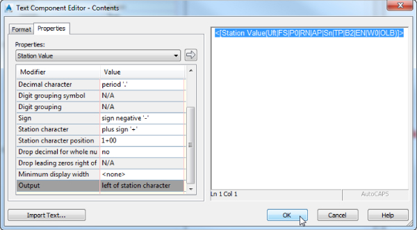
Figure 18.34 Modifying the Station Value Output value in the Text Component Editor dialog
- Click OK to close the Text Component Editor dialog.
- Click OK to close the Label Style Composer dialog.
- Keep the drawing open for the next part of the exercise.
The label style now shows in your label styles, but it hasn't been applied to any alignments yet.
Geometry Points
Geometry points reflect the PC, PT, and other points along the alignment that define the geometric properties. The existing label style was not configured to be plan-readable, so you'll copy it and make a minor change in this exercise. You need to have completed the previous exercise to begin working on the following exercise.
- Continue working in the
1805_Alignment&ProfileLabels.dwg(1805_Alignment&ProfileLabels_METRIC.dwg) file. - Expand the Alignment Label Styles Station Geometry Point branch.
- Right-click Perpendicular With Tick, and select Copy to open the Label Style Composer.
- On the Information tab, change the name to Perpendicular with Line.
- Switch to the General tab.
- Change the Readability Bias setting to 90.
This value will force the labels to flip at a much earlier point.
- Switch to the Layout tab and make these changes:
- Change the active component selection to the one named Tick.
- Click the Delete Component button (the red X).
 Choose Line from the Create Component drop-down.
- Change Angle to 90.
- Change back to the Geometry Point & Station component.
- Change the Anchor Component to Line.1.
- Change the Anchor Point to End.
- Change Rotation Angle to 0.
- Click OK to close the Label Style Composer dialog.
This new style flips the plan-readable labels sooner and includes a line with the label. Next, you will put the styles together in a set.
Alignment Label Set
Once you have several labels you want to use on an alignment, it is time to save them as an alignment label set. You need to have completed the previous exercise in order to begin working on the following exercise.
- Continue working in
1805_Alignment&ProfileLabels.dwg(1805_Alignment&ProfileLabels_METRIC.dwg). You must have completed the previous exercises to continue. On the Settings tab of Toolspace, expand the Alignment Label Styles Label Sets branch. - Right-click Label Sets, and select New to open the Alignment Label Set dialog.
- On the Information tab, change the name to Paving.
- Switch to the Labels tab.
- Set the Type drop-down to the Major Stations option and the Major Station Label Style drop-down to the Index Station style you just created; then click the Add button.
- Set the Type drop-down to the Minor Stations option and the Minor Station Label Style drop-down to the Tick option; then click the Add button.
- Set the Type drop-down to Geometry Points and the Geometry Point Label Style drop-down to Perpendicular With Line. Then click the Add button to open the Geometry Points dialog, as shown Figure 18.35.
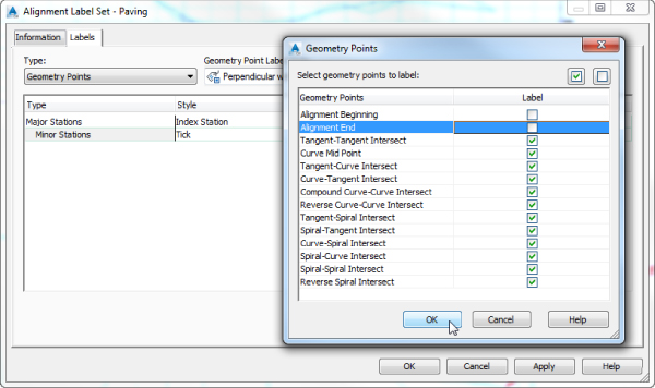
Figure 18.35 Deselecting the Alignment Beginning and Alignment End geometry point check boxes
- Deselect the Alignment Beginning and Alignment End check boxes as shown, and then click OK to dismiss the dialog.
Three label types will appear in the Alignment Label Set dialog.
- Click OK to dismiss this dialog.
In the next exercise, you'll apply your label set to the example alignment and then see how an individual label can be changed from the set. You need to have completed the previous exercise in order to begin working on the following exercise.
- Continue working in the
1805_Alignment&ProfileLabels.dwg(1805_Alignment&ProfileLabels_METRIC.dwg) file. Select the Example alignment on screen. - On the alignment's contextual tab, click to expand the Add Labels button under the Labels & Tables panel and choose Add/Edit Station Labels to display the Alignment Labels dialog.
This dialog shows which labels are currently applied to the alignment. Initially, it will be empty.
- Click the Import Label Set button near the bottom of this dialog.
Any labels appearing in this listing will be replaced by the labels in the set that is imported.
- In the Select Label Set dialog, use the drop-down to select the Paving label set and click OK.
The Alignment Labels list populates with the option you selected.
- Click OK to dismiss the dialog.
- When you finish, press Esc to be sure you have deselected your alignment, and zoom in on any of the major station labels.
- Hold down the Ctrl key, and select one of the major station labels.
Notice that a single label is selected, not the label set group.
- Now that the single label is selected, drag the grip to place it into dragged state. Then click the circular grip to reset the label to its original position.
- While the label is still selected, access the AutoCAD properties palette by pressing the Ctrl+1 key combination. You can access the same tool palette by using the button found in the General Tools panel of the contextual tab.
The Properties palette appears, allowing you to pick another label style from the Major Station Label Style drop-down.
- Change the Label Style value to Parallel With Tick, and change the Flipped value to True, as shown in Figure 18.36.
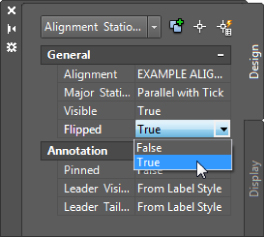
Figure 18.36 Modifying a single label's properties through the base AutoCAD properties palette
- Press Esc to deselect the label item.
If you add labels to an alignment and like the look of the set, use the Save Label Set option. By using alignment label sets, you'll find it easy to standardize the appearance of labeling and stationing across alignments. Building label sets can take some time, but it's an easy, effective way to enforce standards.
Compare your drawing at this point against the 1805_Alignment&ProfileLabels_A.dwg (1805_Alignment&ProfileLabels_A_METRIC.dwg) file if needed.
Station Offset Labeling
Beyond labeling an alignment's basic stationing and geometry points, you may want to label points of interest in reference to the alignment. Station offset labeling is designed to do just that. In addition to labeling the alignment's properties, you can include references to other object types in your station-offset labels. The objects available for referencing are as follows:
- Other alignments
- COGO points
- Parcels
- Profiles
- Surfaces
- Survey figures
In Chapter 10, “Advanced Corridors, Intersections, and Roundabouts,” you used special alignment labels that referenced other alignments to make adjusting your design easier. In this exercise, you will make a similar type of label. The label you create in the following exercise finds the intersection of two alignments. You need to have completed the previous exercise in order to begin working on the following exercise:
- Continue working with the finished version of your previous exercise; otherwise use the
1805_Alignment&ProfileLabels_A.dwg(1805_Alignment&ProfileLabels_A_METRIC.dwg) drawing file. - On the Settings tab, expand Alignment Label Styles Station Offset.
- Right-click the Station And Offset style, and select Copy to open the Label Style Composer dialog.
- On the Information tab, change the name of your new style to Alignment Intersection.
Make it a habit to update the description of the new label to reflect the intent of that label every time you copy or define a new label style.
- Switch to the Layout tab. In the Component Name drop-down, select Marker, and click the red X to delete the component.
- Change the name of the Station Offset component to Main Alignment.
- In the Contents field, click the ellipsis button to bring up the Text Component Editor dialog.
- Select the text in the preview area and delete it all.
- Type Sta. in the preview area; be sure to leave a space after the period.
- In the Properties drop-down field, select Station Value, and set Precision to 0.01.
- Click the arrow in the Text Component Editor dialog; add a space after the inserted text.
- In the Properties drop-down field, select Alignment Name.
- Click the arrow to add this bit of code to the preview.
- Click your mouse in the preview area, and add a space after the inserted text and an equal sign ( =).
Your Text Component Editor dialog should look like Figure 18.37.
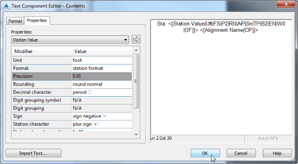
Figure 18.37 The start of the alignment label style
- Click OK to return to the Label Style Composer dialog.
- Under the Border property, set the Visibility field to False.
- Click the Create Component drop-down and select Reference Text.
- In the Select Type dialog that appears, select Alignment and click OK.
- Change the name to Intersecting Alignment.
- In the Anchor Component field, select Main Alignment.
- In the Anchor Point field, select Bottom Left.
- In the Attachment field, select Top Left.
When you choose the anchor point and attachment point in this fashion, the bottom left of the Main Alignment text is linked to the top left of the Intersection Alignment text.
- Click in the Contents field, and click the ellipsis button to open the Text Component Editor dialog.
- Delete the default label text that currently appears in the preview area.
- Type Sta. in the preview area; be sure to leave a space after the period.
- In the Properties drop-down, select Station Value, and set Precision to 0.01.
- Click the insert arrow in the Text Component Editor dialog and add a space after the inserted text.
- In the Properties drop-down, select Alignment Name.
- Click the insert arrow.
- Click OK to exit the Text Component Editor dialog, and click OK again to exit the Label Style Composer dialog.
- Add the label to the drawing by selecting the Annotate tab Labels & Tables panel and clicking the top half of the Add Labels button.
- Change the label settings to match those shown in Figure 18.38, and click Add.
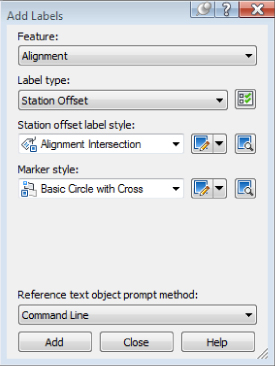
Figure 18.38 Adding the new alignment label
The same label could have been added using the Station Offset - Fixed Point option. This option is more likely to be used if the point of intersection between the alignments does not change. Therefore, consider your intent when using either of the labeling options.
- Watch the command line for placement instructions. You will be prompted to select the main alignment, the station along the alignment, which is the intersection point of both alignments, and the offset. You will then be prompted to select the intersecting alignment.
- Press Esc to complete the labeling command.
- Click the label to select it and reveal the grips. Select the square grip and drag it away from the current location to form a leader.
Your completed label should look like Figure 18.39.
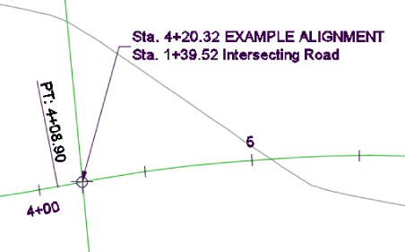
Figure 18.39 The completed alignment label with reference text
Compare your drawing at this point against the file 1805_Alignment&ProfileLabels_B.dwg (1805_Alignment&ProfileLabels_B_METRIC.dwg) if needed.
Profile Labels
It's important to remember that the profile and the profile view aren't the same thing. The labels discussed in this section are those that relate directly to the profile. This usually means station-based labels, individual tangent and curve labels, or grade breaks. You'll look at individual label styles for these components and then at the concept of the label set.
Horizontal Alignment Profile Labels
As with alignments, you apply labels to profiles in the form of profile label sets. For now, though, in this exercise you'll learn how to add alignment labels that describe the horizontal data along a profile object. You will need to have completed the previous exercise in order to begin working on the following exercise:
- Continue working with the finished version of your previous exercise; otherwise use the
1805_Alignment&ProfileLabels_B.dwg(1805_Alignment&ProfileLabels_B_METRIC.dwg) file. - Pick the blue layout profile (the profile with two vertical curves) to activate the profile object.
 From the Profile contextual tab Labels panel, select Edit Profile Labels to display the Profile Labels dialog (see Figure 18.40).
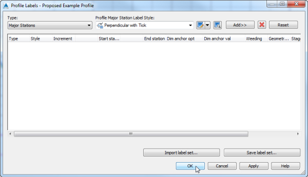
Figure 18.40 An empty Profile Labels dialog
Selecting the type of label from the Type drop-down changes the Style drop-down to include styles that are available for that label type. Next to the Style drop-down are the usual Style Edit/Copy button and a preview button. Once you've selected a style from the Style drop-down, clicking the Add button places it on the profile. The middle portion of this dialog displays information about the labels that are being applied to the profile selected; you'll look at that in a moment.
- Choose the Major Stations option from the Type drop-down.
The name of the second drop-down changes to Profile Major Station Label Style to reflect this option.
- Set the style to Perpendicular With Tick in this drop-down.
- Click Add to apply this label to the profile.
- Choose Horizontal Geometry Points from the Type drop-down.
The name of the Style drop-down changes to Profile Horizontal Geometry Point.
- Select the Horizontal Geometry Station style, and click Add again to display the Geometry Points dialog shown in Figure 18.41.
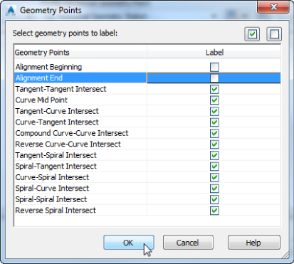
Figure 18.41 The Geometry Points dialog appears when you add labels to horizontal geometry points.
This dialog lets you apply different label styles to different geometry points if necessary.
- Deselect the Alignment Beginning and Alignment End rows, as shown in Figure 18.41, and click OK to close the dialog.
- Click the Apply button, and then drag the dialog out of the way to view the changes to the profile (see Figure 18.42).
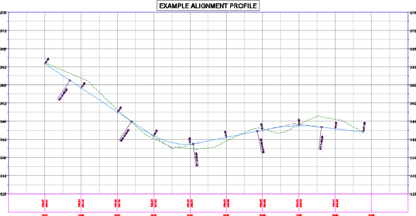
Figure 18.42 Labels applied to major stations and alignment geometry points
- In the middle of the Profile Labels dialog, change the Increment value in the Major Stations row to 50′ (10 m), as shown in Figure 18.43.
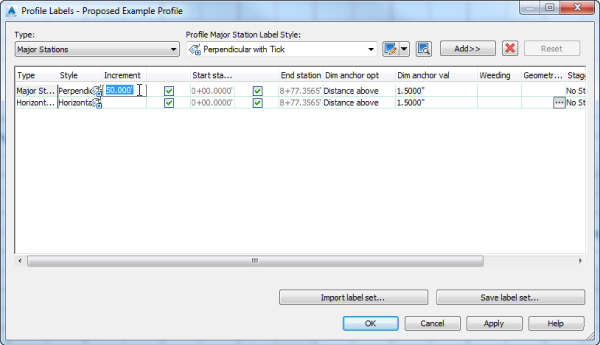
Figure 18.43 Modifying the Major Stations labeling increment
This modifies the labeling increment only, not the grid or other values.
- Click OK to close the Profile Labels dialog.
- Press Esc to deselect the layout profile.
As you can see, applying labels one at a time could turn into a tedious task. After you learn about the types of labels available, you'll revisit this dialog and look at the two buttons at the bottom for dealing with label sets.
Line Labels
Line labels in profiles are typically used to convey the slope or length of a tangent segment. In this exercise, you'll add a length and slope to the layout profile. You will need to have completed the previous exercise in order to begin working on the following exercise:
- Continue working in the
1805_Alignment&ProfileLabels.dwg(1805_Alignment&ProfileLabels_METRIC.dwg) file. - Switch to the Settings tab of Toolspace.
- Expand the Profile Label Styles Line branch.
- Right-click Percent Grade, and select the Copy option to open the Label Style Composer dialog and create a duplicate style.
- On the Information tab, change the name to Length and Percent Grade.
- Switch to the Layout tab and make these changes:
- Change Attachment to Top Center.
- Set the Y-offset to -0.025” (-1 mm).
- Set Background Mask to True and Border Visibility to False.
- Click the Value field next to Contents and click the ellipsis to enter the Text Component Editor dialog.
- Change the Properties drop-down to the Tangent Slope Length option and the Precision value to 0.01, as shown in Figure 18.44.
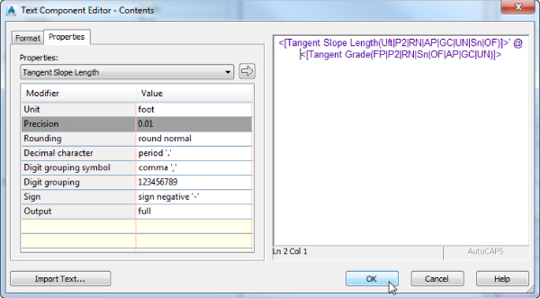
Figure 18.44 The Text Component Editor dialog with the values for the Tangent Slope Length entered
- Put your cursor at the beginning of the existing text in the preview window, click the arrow, and then add a foot symbol (or m for meter), a space, an @ symbol, and another space in the editor's preview pane so that it looks like Figure 18.44.
- Click OK to close the Text Component Editor dialog, and click OK again to close the Label Style Composer.
- Pick the layout profile. From the Profile contextual tab Labels panel, select Edit Profile Labels to display the Profile Labels dialog.
- Change the Type drop-down to the Lines option. The name of the Style drop-down changes to Profile Tangent Label Style. Select the Length And Percent Grade option.
- Click the Add button, and then click OK to exit the dialog.
- Press Esc to deselect the layout profile.
The profile view should look like Figure 18.45.
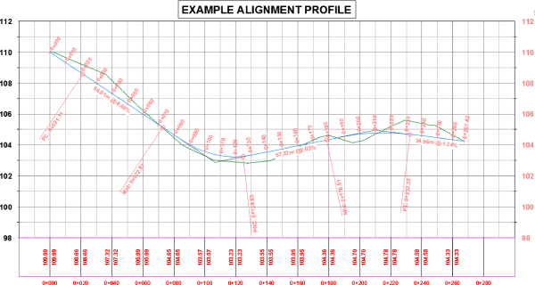
Figure 18.45 A new line label applied to the layout profile
Curve Labels
Vertical curve labels are one of the most confusing aspects of profile labeling. Many people become overwhelmed rapidly, because there's so much that can be labeled and there are so many ways to get all the right information in the right place. In this quick exercise, you'll look at some of the special label anchor points that are unique to curve labels and how they can be helpful. You will need to have completed the previous exercise in order to begin working on the following exercise:
- Continue working in the
1805_Alignment&ProfileLabels.dwg(1805_Alignment&ProfileLabels_METRIC.dwg) file. - Pick the layout profile. From the Profile contextual tab Labels panel, select Edit Profile Labels to display the Profile Labels dialog.
- Choose the Crest Curves option from the Type drop-down.
The name of the Style drop-down changes to Profile Crest Curve Label Style.
- Select the Crest Only option.
- Click the Add button to apply the label to the list.
- Choose the Sag Curves option from the Type drop-down.
The name of the Style drop-down changes to Profile Sag Curve Label Style.
- Select the Sag Only label style. Click the Add button to apply the label.
- Click OK to close the dialog.
- Press Esc to deselect the layout profile.
Your profile should look like Figure 18.46.
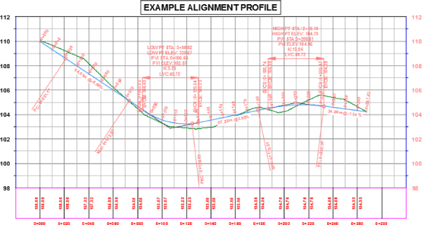
Figure 18.46 Curve labels applied with default Dim Anchor values
Most labels are applied directly on top of the object being referenced. Because typical curve labels contain a large amount of information, putting the label right on the object can yield undesired results. In the following exercise, you'll modify the label settings to review the options available for curve labels. You will need to have completed the previous exercise in order to begin working on the following exercise:
- Continue working in the
1805_Alignment&ProfileLabels.dwg(1805_Alignment&ProfileLabels_METRIC.dwg) file. - Pick the layout profile. From the Profile contextual tab Labels panel, select Edit Profile Labels to display the Profile Labels dialog.
- Scroll to the right, and change both Dim Anchor Opt values for Crest Curves and Sag Curves to Graph View Top. You may need to make the columns wider to view the names.
- Change the Dim Anchor Val for both curves to -2.25” (-40 mm), and click OK to close the dialog.
- Press Esc to deselect the layout profile.
Your drawing should look like Figure 18.47.
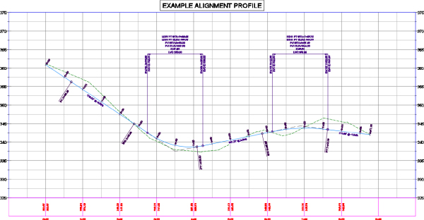
Figure 18.47 Curve labels anchored to the top of the graph
The labels can also be grip-modified to move higher or lower as needed. By using the top or bottom of the graph as the anchor point, you can apply consistent and easy labeling to the curve, regardless of the curve location or size.
Grade Breaks
The last label style typically involved in a profile is a grade-break label at PVI points that don't fall inside a vertical curve, such as the beginning or end of the layout profile. Additional uses include things like water-level profiling, where vertical curves aren't part of the profile information or existing surface labeling. In this exercise, you'll add a grade-break label and look at another option for controlling how often labels are applied to profile data. You will need to have completed the previous exercise in order to begin working on the following exercise:
- Continue working in the
1805_Alignment&ProfileLabels.dwg(1805_Alignment&ProfileLabels_METRIC.dwg) file. - Pick the green surface profile (the irregular profile). From the Profile contextual tab Labels panel, select Edit Profile Labels to display the Profile Labels dialog.
- Choose Grade Breaks from the Type drop-down.
The name of the Style drop-down changes to Grade Breaks.
- Select the Station Over Elevation style and click the Add button.
- Click Apply, and drag the dialog out of the way to review the change.
A sampled surface profile has grade breaks everywhere the alignment crosses a surface TIN line. Why wasn't your view coated with labels?
- Scroll to the right, and change the Weeding value to 150′ (45 m). Click OK.
- Select one of the new grade-break labels. Use the square grip at the location where the label touches the profile to form a leader and clean up any labels that overlap.
The profile labels should appear as shown in Figure 18.48.
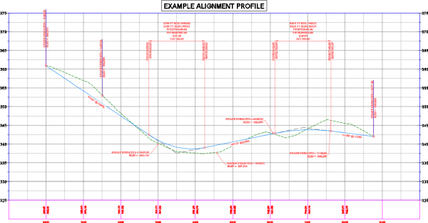
Figure 18.48 The grade-break labels on a sampled surface are starting to get crowded, so weeding combined with dragged labels can bring some clarity to the profile view.
- Click OK to dismiss the dialog.
- Press Esc to deselect the layout profile.
Weeding lets you control how frequently grade-break labels are applied. This makes it possible to label profiles with frequent grade breaks, such as a surface profile, at even increments instead of at every PVI.
As you've seen, there are many ways to apply labeling to profiles, and applying these labels to each profile individually could be tedious. In the next section, you'll build a label set to make this process more efficient.
Profile Label Sets
Applying labels to both crest and sag curves, tangents, grade breaks, and geometry with the label style selection and various options can be monotonous. Thankfully, Civil 3D gives you the ability to use label sets, as in alignments, to make the process quick and easy. In this exercise, you'll apply a label set, make a few changes, and export a new label set that can be shared with team members or imported to the Civil 3D template. You will need to have completed the previous exercise in order to begin working on the following exercise:
- Continue working in the
1805_Alignment&ProfileLabels.dwg(1805_Alignment&ProfileLabels_METRIC.dwg) file. - To tidy things up, you can select one of the grade-break labels from the previous exercise. Press Delete on your keyboard to remove the label.
- Pick the layout profile. From the Profile contextual tab Labels panel, select Edit Profile Labels to display the Profile Labels dialog.
- Click the Import Label Set button near the bottom of the dialog to display the Select Label Style Set dialog.
- Select the Complete Label Set option from the drop-down, and click OK.
- Click OK again to close the Profile Labels dialog and see the profile view. Press Esc to clear any selection.
The label set you chose contains curve labels, grade-break labels, and line labels.
- Pick the layout profile. From the Profile contextual tab Labels panel, select Edit Profile Labels to display the Profile Labels dialog.
- Click Import Label Set to display the Select Label Style Set dialog.
- Select the No_Labels option from the drop-down, and click OK.
All the labels from the listing will be removed.
In the next steps, you will add labels to the listing and save the listing as its own label set for future use.
- Set Active Type to Lines. Set Profile Tangent Label Style to Length And Percent Grade, and click Add.
- Set Active Type to Grade Breaks. Set Profile Grade Break Label Style to Station Over Elevation, and click Add.
- Set Type to Crest Curves. Set Profile Crest Curve Label Style to Crest Only, and click Add.
- Set Type to Sag Curves. Set Profile Sag Curve Label Style to Sag Only, and click Add.
- Set the Crest Curves and Sag Curves label types to use Graph View Top as the Dim Anchor Opt.
- Set both Dim Anchor Val fields to -1.5” (-40 mm), as shown in Figure 18.49.
Figure 18.49 Four label types and dimension anchor settings in the label set to be saved
- Click the Save Label Set button to open the Profile Label Set dialog and create a new profile label set.
- On the Information tab, change the name to Road Profile Labels.
- Click OK to close the Profile Label Set dialog.
- Click OK to close the Profile Labels dialog.
- Press Esc to deselect the layout profile if it's still selected.
- On the Settings tab of Toolspace, select Profile Label Styles Label Sets.
Note that the Road Profile Labels set is now available for sharing or importing to other profile label dialogs.
Save and close the drawing. A saved copy of this drawing, 1805_Alignment&ProfileLabels_FINISHED.dwg (1805_Alignment&ProfileLabels_METRIC_FINISHED.dwg), is available from the book's web page.
Label sets are the only way to apply profile labeling uniformly. When you're working with a well-developed set of styles and label sets, going from sketched profile layout to plan-ready output is quick and easy.
Advanced Style Types
Now that you are familiar with the basics of label styles, you are ready to take your skills to the next level. The styles in the following section combine aspects of label styles and object styles. You will cover object styles more in depth in Chapter 19, “Object Styles.”
You have a great deal of control over every detail, even ones that may seem trivial. Instead of being bogged down trying to understand every option, don't be afraid to try a “trial and error” approach. If you make a change you don't like, you can always edit the style until you get it right.
Table Styles
Civil 3D does a beautiful job of placing dynamically linked data tables that relate to your objects. The tables use the Text Component Editor to grab dynamic information from your data. You also have control over fill colors, table headings, and how the data is sorted.
For the table style, the Data Properties tab contains all the column information. You can add columns by clicking the plus sign. You can remove columns by highlighting the column you want to remove and clicking the Delete button. You change column order by dragging them around and dropping them where you want them to go, as shown in Figure 18.50.
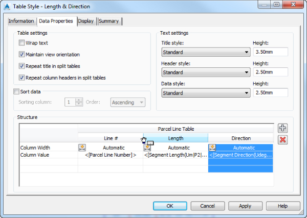
Figure 18.50 Modifying table column positions. Selecting one column and dragging it to change its position in the list.
In the following exercise, you will see the basic steps of modifying a table style. Now that you understand the ins and outs of the Label Style Composer, this procedure should be a breeze:
- Open the
1806_Tables.dwg(1806_Tables_METRIC.dwg) file, which you can download from this book's web page.This file contains a parcel line table whose style you will modify.
- Zoom into the parcel line table.
Notice that there are several things you will want to change:
- The line numbers are out of order.
- The directions have far too much precision.
- The length does not display units.
All that is about to change.
 Click the table to select it. From the Table contextual tab Modify panel, select the Table Properties drop-down and choose Edit Table Style.
- Switch to the Data Properties tab.
The Data Properties tab (Figure 18.51) is the main control area for all table styles. This is where you set behavior, text styles, and sizes for fields.
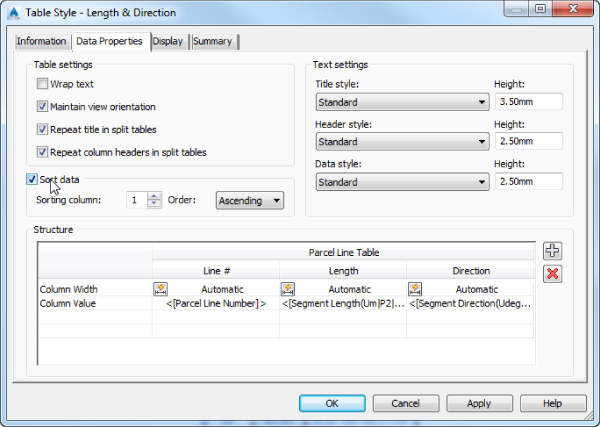
Figure 18.51 The Data Properties tab for table styles. Sorting of the data can be enabled with a simple toggle.
- Place a check mark next to Sort Data, and set the Sorting column to 1.
Column 1 corresponds to the Column Value containing the Parcel Line Number. Set the Order option to Ascending. The Ascending option will ensure that the parcel numbers are listed in the table from the lowest to highest value.
- Double-click the column heading field for Length.
Doing so opens a stripped-down version of the Text Component Editor dialog. Headings and table titles are static text only; therefore, only the text formatting tools are shown.
- Add (feet) or (meters) after the column heading to add a proper units heading to the column, as shown in Figure 18.52, and click OK.
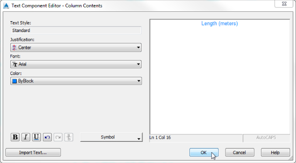
Figure 18.52 Adding static text to a table column heading
- Double-click the Direction Column Value field below the column heading.
Doing so opens the Text Component Editor dialog, similar to what you've used in earlier exercises.
- Click the text in the preview area so that it becomes highlighted.
- Change Precision to 1 Second.
- Click the arrow to update the text. Click OK.
- Click OK to complete the table style modifications.
Save and close the drawing. A saved copy of this drawing, 1806_Tables_FINISHED.dwg (1806_Tables_METRIC_FINISHED.dwg), is available from the book's web page.
Code Set Styles
Code set styles determine how your assembly design will appear, and they are used in many places. A code set style is in play when you first create your assembly. One is used in corridor creation and in the Section Editor. The most apparent use of a code set style is in section views.
A code set style is a collection of many other styles. In a code set style you will find the following:
- Link styles and link label styles
- Points styles, point label styles, and feature line styles
- Shapes styles and shape label styles
- Quantity takeoff pay items
- Render materials for visualization tasks
When naming your code set style, you'll find it helpful to have the name of the set reflect its use. Multiple code set styles are needed because of different applications of their use. When you are designing an assembly, you may want to see more labels than when you are getting ready to plot the assembly in a cross-section sheet. Labeling that is useful in a cross-section sheet may obstruct your view of the design when working with it in the corridor cross-section editor.
The hardest part of working with code set styles is figuring out the name of the link or point you want to label. Luckily, it is unusual for users to label shapes, so you won't need to worry about those. The names of each point or link can be found in the subassembly properties. Most of the links and points are logically named, but there's no harm in a little trial and error if you are not sure.
Shapes
Shapes are the areas that define materials. Because people don't usually label these materials in a section view, you won't be experiencing these in an exercise.
One heads-up, however: Resist the temptation to use a hatch pattern on shapes where multiple cross-section views will be created. Solid fills and no patterns are your best bet to avoid performance issues and the annoying “Hatch pattern is too dense” warning.
Links and Link Labels
You learned in Chapter 8, “Assemblies and Subassemblies,” that a link is the linear part of a subassembly. The object style for the link itself is very simple—just a single linear component. The label for a link is usually expressed as a percent grade or as a slope ratio.
In the following exercise, you will modify a code set style to apply link labels to an assembly:
- Open the
1807_CodeSetStyles.dwg(1807_CodeSetStyles_METRIC.dwg) file, which you can download from this book's web page.This file contains corridor and cross-section views. Zoom into one of the cross-section views so you can observe the changes as you apply them to the code set style.
- From the Settings tab of Toolspace, expand General Multipurpose Styles Code Set Styles; right-click All Codes, and select Edit.
- On the Codes tab under the Link category, select Pave, and click the Label Tag icon in the Label Style column, as shown in Figure 18.53.
Figure 18.53 Adding labels to the link codes in the code set style
- In the Pick Style dialog, select the Flat Grades label style and click OK; then click Apply to examine the change on the cross sections.
You should see that the lanes now have slope information labeled.
- Under the Link category, locate Daylight; click the Label Tag icon in the Label Style column, and select Steep Grades as the label style.
- Click OK, and then click OK to dismiss the All Codes label style and see what is happening with the cross section.
The cross sections should resemble Figure 18.54.
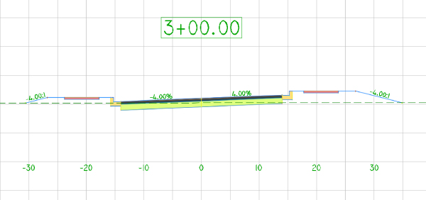
Figure 18.54 Cross section with link labels applied to pave and daylight links
Points and Point Labels
A common frustration for new users of Civil 3D is the marker styles and their labels. For cross-section views, you may not want points to display at all. In the following exercise, you will create a new code set style, modify point codes, and add more labels to the sections. You need to have completed the previous exercise in order to begin working on the following exercise:
- Continue working in
1807_CodeSetStyles.dwg(1807_CodeSetStyles_METRIC.dwg). - From the Settings tab of Toolspace, expand General Multipurpose Styles Code Set Styles. Right-click All Codes and select Copy.
- On the Information tab, rename the style to All Codes-Plotting.
- On the Codes tab, locate and expand the Point category. Locate the Back_Curb point and click the Label Tag icon in the Label Style column. In the Pick Style dialog, set the style to Offset Elevation. Click OK.
- Repeat step 4 to set the label style for Sidewalk_Out to Offset Elevation.
- Click the first point name, <default>. While holding down the Shift key on your keyboard, scroll down to the last point listing, Top_Curb. With all of the points selected, click the Tag icon in the Style column and change the style to _No Markers. Click OK.
The Code Set Style dialog should resemble Figure 18.55.
Figure 18.55 Points set to _No Markers and labels set to Offset Elevation
- Click OK.
You can't see any changes to your cross sections yet because the style is not active.
- Select a section view by selecting its corresponding section view station label. From the Section Views contextual tab Modify View panel, select the top half of the View Group Properties icon.
- On the Sections tab, change the style of Example Corridor to the All Codes-Plotting style you created, as shown in Figure 18.56, and click OK.
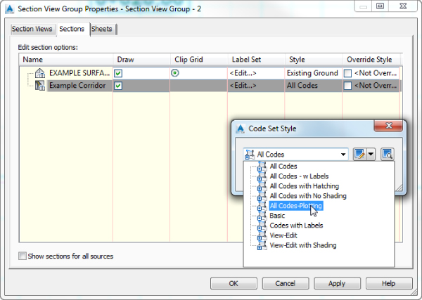
Figure 18.56 Setting the code set style current on the section views
- Click OK again to complete the changes to the Section View Group Properties dialog.
Your section view should resemble Figure 18.57.
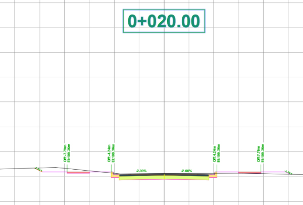
Figure 18.57 New code set style applied to the : section view
The created section views use the legacy labeling for points. We will now use the newly introduced feature of labeling corridor sections using section labels for corridor points, instead of code sets.
- From the Settings tab of Toolspace, expand Section Label Styles Corridor Points. Right-click the branch and choose New.
- In the Information tab name this new style Corridor Points.
- In the Layout tab, for the Line component set Fixed Length to 2 (40 mm for metric users).
- Still in the Layout tab, change the active Component Name to the one named Point Code. Then set the following:
- Anchor Component to Line
- Anchor Point to End
- Attachment to Bottom Right
- Y Offset to 0.025 (0.50 mm for metric users).
- Still in the Layout tab, change the active Component Name to the one named Offset And Elevation. Then set the following:
- Anchor Component to Point Code
- Anchor Point to Bottom Right
- Attachment to Top Right
- Y offset to -0.05 (-1.00 mm for metric users).
- In the Contents editor set the precision for both the Subassembly Point Offset and the Subassembly Point Elevation coding to 0.01 using the same steps that we followed through this chapter.
- In the right pane of the Contents editor, modify the text before the Subassembly Point Offset to show OS: and a space and the text before the Subassembly Point Elevation to EL: and a space. Also eliminate the comma in between the two components. (See Figure 18.58 for the layout of items needed in the contents.)
Figure 18.58 Content Editor for the Corridor Points label
- Click OK to finish creating the style.
- At the command line type in
CORRIDORSECTIONLABELSCONVand hit Enter, and at theSelect Section view you want to convert:prompt select one of the section views by picking the section view label. Press Enter, and from the next prompt select Corridor Points Style Labels.You will not notice any labels assigned yet.
- Select the corridor section, and from the contextual tab, within the Labels panel, choose Edit Section Labels for the Section Labels dialog to show up.
- In the Section Labels dialog, change the Type to Corridor Points, and from Section Corridor Points Label Style, select the Corridor Points and click the Add button. Click OK to dismiss the dialog box.
Now you will not notice the new labels applied to the section view. You can convert the labels back and forth by issuing the same command and picking the desired output. Your converted section view will look like Figure 18.59.
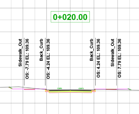
Figure 18.59 Section view using the newly introduced Corridor Points Labels feature
Save and close the drawing. A saved copy of this drawing, 1807_CodeSetStyles_FINISHED.dwg (1807_CodeSetStyles_METRIC_FINISHED.dwg), is available from the book's web page.
The Bottom Line
- Override individual labels with other styles. In spite of the desire to have uniform labeling styles and appearances between alignments within a single drawing, project, or firm, there are always exceptions. Using the Ctrl+click method for element selection, you can access commands that let you modify labels and even change their styles.
- Master It Open the drawing
MasterIt_1801.dwg(MasterIt_1801_METRIC.dwg). Create a copy of the Perpendicular With Tick Major Station style called Major With Marker. Change Tick Block Name to Marker Pnt. Replace some (but not all) of your major station labels with this new style.
- Master It Open the drawing
- Create a new label set for alignments. Label sets let you determine the appearance of an alignment's labels and quickly standardize that appearance across all objects of the same nature. By creating sets that reflect their intended use, you can make it easy for a designer to quickly label alignments according to specifications with little understanding of the requirement.
- Master It Continue working in the
MasterIt_1801.dwg(MasterIt_1801_METRIC.dwg) file if you completed the previous exercise, or open theMasterIt_1801_FINISHED.dwg(MasterIt_1801_METRIC_FINISHED.dwg) file. Create a new label set containing only the new major station label defined in the previous exercise, and apply it to all the alignments in that drawing.
- Master It Continue working in the
- Create and use expressions. Expressions give you the ability to add calculated information to labels or add logic to label creation.
- Master It Continue working in the
MasterIt_1801.dwg(MasterIt_1801_METRIC.dwg) file or open theMasterIt_1802_FINISHED.dwg(MasterIt_1802_METRIC_FINISHED.dwg) file, and create an expression called Top of Curb that adds 0.5′ (0.15 m) to a surface elevation. Use the expression in a spot elevation label that shows both the surface elevation and the expression-based elevation to two decimal precision.
- Master It Continue working in the
- Apply a standard label set to profiles. Standardization of appearance is one of the major benefits of using Civil 3D styles in labeling. By applying label sets, you can quickly create plot-ready profile views that have the required information for review.
- Master It Continue working in the
MasterIt_1801.dwg(MasterIt_1801_METRIC.dwg) file or open theMasterIt_1803_FINISHED.dwg(MasterIt_1803_METRIC_FINISHED.dwg) file, and apply the Road Profile Labels label set to all layout profiles.
- Master It Continue working in the