
Chapter 5
Multiplatform Interoperability: Working with 2D and 3D Data
This chapter introduces you to the best-practice techniques for importing data into your Autodesk® Revit® 2015 database, either directly into the project file or via a loadable family. The chapter also covers which data to use and when in the project life cycle to use it. Selecting a button that performs the import is easy—but, more important, why are you doing it? And for that matter, should you be doing it?
Not only can you import 2D information, but 3D solids contained in an import can now be exploded and manipulated within Revit. These two types of databases are different, so when you have to start working with other consultants who use other data types, you may experience issues such as the following:
- Loss of Performance Typically, importing any other file format into Revit can be a bad idea. Yes, it is possible—but like eating too much candy, your file size can start to bloat and slow you down. Keep your project file lean, and minimize its intake of sweets whenever you can! But, keeping the food analogy going, cleaning that data—like washing your vegetables—can produce some excellent results. It's all in the preparation.
- Difficulties Displaying and Printing Data Exactly the Same One of the most annoying problems is issues with fonts either not being installed or, in the case of legacy DWG data, not being fully supported and therefore never displaying in the same way as originally intended.
- Data Loss Many issues can cause data loss in your final documentation. Issues include linked files being unloaded, workset visibility being incorrectly set, and printer driver problems.
We must ask, Is 2D really 2D? An Autodesk® AutoCAD® 2D DWG file can show up in a 3D view. Do you want it to?
In this chapter, you will learn to do the following:
- Decide which type of data you want to use on a project
- Link data consistently and in the correct location
- Prepare data prior to import
2D Data Types
Revit works reasonably well with file types other than native RVT project files. Many of the issues you will encounter are due to the differences between existing CAD technologies, which for the most part rely on elements (lines, arcs, and circles), while the newer BIM technologies are founded on object-based parametric databases.
The AutoCAD file format has differences even among drawings that are created in the same AutoCAD version. For example, virgin AutoCAD can sometimes produce an error when opening a DWG file that was created in any of the vertical products (AutoCAD® Civil 3D®, AutoCAD® Architecture, AutoCAD® MEP, and so on). When you import this file into Revit, the error shown in Figure 5.1 is displayed.
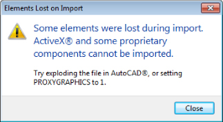
Figure 5.1 Elements Lost On Import warning
An additional message is the one displayed in Figure 5.2. Although not exactly an error message, it should make the user take notice—were you actually expecting objects to be in AutoCAD model space? If so, then there may be some fidelity issues with the drawing file that you are trying to link.
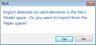
Figure 5.2 No valid elements
The issue you face here is whether the “intelligent” data in the AutoCAD file is important or, for the sake of the Revit project, can you explode (if possible) the objects to base elements that can be read in Revit?
You have other options if the data has been created in one of the vertical products. You'll learn about these options in the section “3D Data Types” later in this chapter.
MicroStation 2D DGN
Revit currently supports AutoCAD versions 2000 through 2015, and most MicroStation versions can be imported. The possible alternatives here include asking the originator to use their version of the Save As command to create an AutoCAD file format that MicroStation can handle, use a specially developed app to export to IFC, or export as a DXF file.
DXF
The Drawing Exchange Format (DXF) has been around for almost as long as DWG and DGN. It is a well-recognized and trusted translation medium between primarily 2D formats. The DXF file format also supports conversions to file formats 2000–2010, although care should be taken when using this format because it is generally regarded as offering the most basic compatibility with the likelihood of the worst fidelity.
2D Data for Standard Details
When importing 2D data for standard details, you may well be linking existing details from your company library. If you are using the same drafting standards in AutoCAD and Revit, this process is relatively easy. However, you might want to take a look at your existing company standards if you are planning on running two systems.
One of the important consideration points relates to the use of the legacy default AutoCAD SHX fonts, such as romans.shx or isocp.shx. The great thing about these fonts for AutoCAD users is that you can control the line weight of the text by utilizing different colors. However, although Revit displays these fonts, their appearance is governed by the SHXFontMap file, which can substitute a TrueType font; you cannot adequately control the line weight of text objects in Revit. In fact, the only way to edit the weight of the text is to make it bold. Again, this process involves editing the AutoCAD drawing. For example, Revit does not recognize all the codes CAD users have used for years, such as the degrees symbol (%%d), underline (%%u), and so on. In this respect, the developers of Revit felt that focusing on more-modern font technologies (TrueType fonts) was more appropriate in the long run than using the much older SHX font approach. Therefore, instead of using line weight, Revit favors a text output that is consistent with most other word processing software.
Thus, in order to use Revit and AutoCAD and have your output identical, you need to change your AutoCAD fonts to TrueType fonts. This has been a hot topic for many people implementing Revit. Once you get past the shock that this is required and that drafting standards need to change, the actual conversion process can be automated in AutoCAD.
When you import a file into Revit, you must ask yourself the following questions:
- Will this be used in more than one view?
- Is the file likely to be updated in other places (perhaps referenced by different projects, Revit and otherwise)?
- Can the drawing be exploded after it is imported? Note the term imported. If a drawing is linked, it cannot be exploded. Neither can it be bound like an X-ref or a linked Revit file. However, using the Import button in the Manage Links dialog box does create this bound condition available in AutoCAD.
Also worth noting is that when exploding an imported object, you have two options: Partial and Full. A partial explosion turns the result into the highest level of lines, circles, arcs, and text while respecting the existence of blocks, which can be partially exploded again. A full explosion reduces the imported drawing into its simplest representation of lines, arcs, circles, and text. Text becomes single lines of text rather than retaining any multiline settings, regardless of the explosion type. Entities not recognized by Revit—points, for example—are not translated and are lost in the explosion process.
When importing or linking into a plan, section, or elevation view, the drawing will show up in multiple views unless you select the Current View Only check box in the Import dialog box. See Figure 5.3.
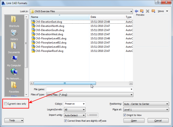
Figure 5.3 Current View Only optionMargin Icon
If the view you are using is either a drafting or a legend view, the Current View Only check box is grayed out, because these views are only 2D.
When importing a file for use as a detail, positioning generally is not as important as when importing an overall plan. The Positioning options for importing are shown in Figure 5.4.
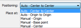
Figure 5.4 Positioning options
For details, you can generally use the manual options and place the details where required. Trying these options in a blank project file before you bring any file into your live project is always a good rule of thumb; it gives you a sense of where the objects are going to be and whether the scale is correct.
Figure 5.5 indicates the options available for import units. Although Auto-Detect is the default option and usually works, sometimes the originator of your imported data is not as rigorous as they should be and their units don't quite match their documentation. So specifying the units is preferable to letting Revit apply a default. Also, the scale used in the view should match the scale intended to display the detail in the original software used to make it. This ensures that geometry, hatching, and fonts will be as close to the same as possible. If this isn't set before importing the detail, then the poor fidelity can compound the issue of units being wrong.
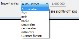
Figure 5.5 Import Units options
You have the option to correct lines that are slightly off axis, as shown in Figure 5.6.
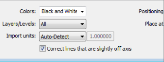
Figure 5.6 Correcting lines that are slightly off axis
This feature should be used with care, however, because those “slightly off-axis lines” may be part of the design intent!
2D Data for Plans, Sections, and Elevations
Let's say that you are using Autodesk Revit MEP and want your staff members to keep using that program, even though you have other projects in your office for which the architect is using traditional CAD-based drafting methods. Should you do these projects in AutoCAD or Revit? Once you have been using Revit for a while, using anything else feels like it takes far too long, and there's all that back-referencing, and checking sections tie up with the plans!
The following Revit workflow is tried and rigorously tested. Your staff members retain their knowledge, and the project design is still coordinated (albeit only with the other building services, not with the architecture—although the architect can provide you with sections as well as plans).
When going down this route, you need to consider how your project team generally works: either in one multiservice file or in multiple project files with only one service. If all services are in one model, linking the plans and sections into that file is probably the best way forward.
Our experience is working with multiple project files—Architecture, Structure, Electrical, HVAC, Fire, Plumbing, and Drainage. This is sometimes born of necessity because the project teams are in different geographic locations. Although a company might have technology to support distributed file servers and project teams on different continents, the reality is that managing this process can be more trouble than it is worth.
In this workflow, linking the 2D files into each project file is an option. The linked files appear only as linked overlays in the same way they do in AutoCAD. Managing the location of multiple linked files in multiple project files is a messy and time-consuming task. You have to rely on users not moving or deleting anything accidentally. Of course, this applies in any project, but the problem can become compounded under these circumstances. The best option here is to have one architectural file, one place to update and manage, and all your services files can be kept at the same stage for printing. This does require some setup at the start of the project, but once it's complete, it is almost as manageable as linking a model from the Revit Architecture software.
The following exercise will take you through linking plans and elevations into a new project file, creating levels and default views that any of the project engineers can use to obtain the prints they require for markup. Although this exercise uses a few of the more basic Revit commands, it is mainly designed to show a best-practice workflow, especially when linking this file into your services project files. At the end on the exercise, you will end up with a 3D wireframe model as shown in Figure 5.7.
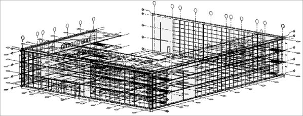
Figure 5.7 3D wireframe model
Follow these steps:
- Create a new Revit MEP 2015 project file using the template
Ch5_Template.rte. This file can be found at www.sybex.com/go/masteringrevitmep2015. - Open the Level 1 floor plan, and from the Insert tab, select Link CAD and select the drawing file
Ch5-FloorplanLevel01.dwg. Use the following settings, shown in Figure 5.8:- Current View Only: Not selected
- Colors: Black And White
- Layers/Levels: All
- Import Units: Auto-Detect
- Correct Lines That Are Slightly Off Axis: Not selected
- Positioning: Auto – Origin To Origin
- Place At: Level 1
- Orient To View: Selected
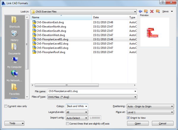
Figure 5.8 Import settings
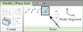
- The next step is to create building grids based on the architectural floor plan. From the Architect tab, select the Grid tool. With this active, use the Pick Lines option from the Draw panel. Although this is a quick method of creating grid lines, be sure to keep an eye on the grid head location. If the lines have been drawn in different directions, the result is that the grids are orientated differently. Clicking the grid head and selecting the adjacent check mark to swap the orientation will work—but only in this view. As long as you create these elements consistently, they will be displayed in a consistent manner through the rest of the project.
Start with Grid 1 and select each subsequent grid, except the intermediate grids. You can come back and do those after creating Grid 10. Once the vertical grids are complete, do the horizontal ones. Starting at A, you will rename this first alphabetic grid and then follow with B, C, and so on. Once all the major grids are created, go back and create the intermediate ones. With this workflow, you have to rename only a few grids rather than every single one.
- With the grids complete, open the North Elevation.
- Navigate back to the Insert tab, select Link CAD, and select the file
Ch5-ElevationNorth.dwg. Use the Auto – Center To Center positioning option, and ensure that Orient To View is checked. - Notice that the elevation drawing, while orientated in the correct plane, is not in the correct location with respect to the levels and grids. Use the Align tool to correct this, aligning Level 1 with 01-Entry Level and Grids 1, as shown in Figure 5.9.
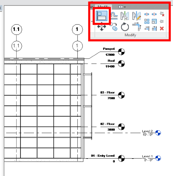
Figure 5.9 Align Linked DWG
- One other thing to notice is that the existing levels do not share the same name as the linked DWG. Select the Level 1 line and click the blue highlighted name of the level. Change this to match the DWG, and do the same for level 2. Revit then asks if you would like to rename corresponding views. Click Yes, as shown in Figure 5.10.
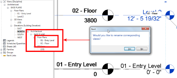
Figure 5.10 Renaming levels
- Create additional levels for levels 03 - Floor, Roof, and Parapet, renaming each level to match the link file. You may find that the created levels do not show up in the Project Browser where you expect. In Figure 5.11, the levels created have ended up filed under Architectural / Power / Floor Plans. To place these views into Architectural / BASE PLANS / Floor Plans, select all three (A), right-click, and select Apply View Template (B). From the Apply View Template dialog, select Architectural Plan (C) and click Apply Properties (D). You will see the views move in the Project Browser (E).
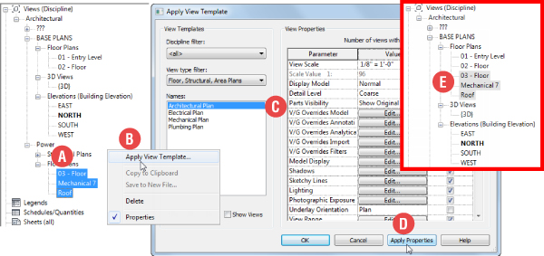
Figure 5.11 Applying the view template
- Repeat step 2, opening each level (02 - Floor, 03 - Floor, and Roof) and linking the following DWG files:
Ch5-FloorplanLevel02.dwgCh5-FloorplanLevel03.dwgCh5-FloorplanRoof.dwg
- With all the floor plans linked, we can turn our attention to the elevations. You already have the North elevation linked (step 5), and looking at the default 3D view, you can see in Figure 5.12 that although the file is aligned correctly in relation to levels and grid 1, it is in the middle of the building. Open 01 - Entry Level plan and use the Align tool to move the elevation to the north “face” of the floor plan.
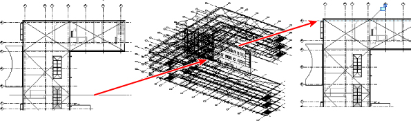
Figure 5.12 Aligning the elevation to the plan
- Repeat steps 5 and 6, opening each of the remaining elevations in turn and linking the following files:
Ch5-ElevationSouth.dwgCh5-ElevationWest.dwgCh5-ElevationEast.dwg
- Repeat step 10 for each elevation. It's a good idea to do this straight after linking each one; that way you don't end up aligning the incorrect one.
- Open floor plan 01 - Entry Level and activate Visibility Graphics. Select the Imported Categories tab and uncheck all the linked DWG files except
Ch5-FloorplanLevel01.dwg.Also, as indicated in Figure 5.13, click the plus sign to expand the layers in the link and turn off anything unwanted - like grids (S-GRIDIDM), for example.
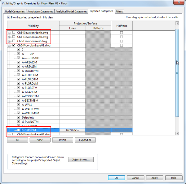
Figure 5.13 Applying visibility/graphic overrides for links
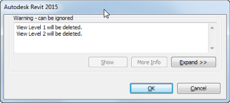
Figure 5.14 Viewing deletions
- Repeat step 13 for all the other floor plans and elevations, leaving only the link file appropriate to each view visible.
When you have finished, open a 3D view. Your “building” should look similar to Figure 5.7.
- Save the file. This can now act as the architectural link file for your entire project.
- Using the same template file you used in step 1, create a new project file. This can be your HVAC documentation model.
- Open the North elevation view and delete the two existing levels. The message that appears, displayed in Figure 5.13, informs you that views are being deleted. This is normal, so click OK.
- Link the file
Ch5_COMPLETE.rvtby using the Origin To Origin method. Notice that none of the linked drawings are visible—you'll adjust that in step 20. - As with a standard Revit project, copy/monitor the levels and grids, and then create your plan views. Each of these views will display only the grids, not the linked drawing files.
- In each of these views, adjust the visibility/graphics to override the view to the required settings, as shown in Figure 5.15.
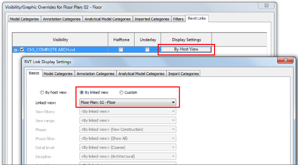
Figure 5.15 Visibility/Graphic Overrides
Whether you're linking or importing CAD data from other formats, although you can use the overrides to change what you see or how you see it, you can also, in fact, use the Import Line Weights option, as shown in Figure 5.16. This enables you to specify a DWG color number and associate it with a pen weight in Revit. This can range from using a series of default standards supplied with the software to loading your own (or partner's) standard, so the weights of lines are the same between CAD and Revit.
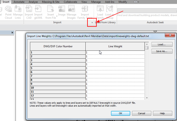
Figure 5.16 Import Line Weights option
In addition, you have the ability to select and query the layers in a linked/imported CAD file. Say, for example, you are unsure of the layering standard in the linked file; you can select that file and then use the Query command, as indicated in Figure 5.17. You can select lines and objects within the link file and choose the option to hide that selection in your current view.
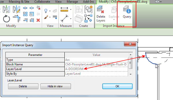
Figure 5.17 Querying imported layers
3D Data Types
This section is easy—well, it should be anyway. You are, after all, importing and manipulating 3D data in a 3D application. What could possibly go wrong?
It all depends on the type of data you want to import or link into your project. Let's start with the easiest—a Revit project file. Surely there cannot be anything difficult with that? What it boils down to, however, is the other users and how they have set up their projects. If you are lucky, they have a lot of experience and, most important, have communicated how the model is constructed to the entire project team.
Much also depends on what you, as an MEP user, want to get out of the project, so let's see.
Revit Project File
Working with external consultants can be very trying at the best of times. Think back to times when all you had to worry about was whether lines had been drawn on the correct layer and whether they were either by layer or by block. Yearning for the old days? Life did seem simpler then, but was it really?
Getting a set of drawings from the architect meant doing some preparation work such as running the odd AutoLISP routine to change layers, linetypes, and color. Then you had to make sure the plans all had the same User Coordinate System (UCS) settings and elevations and that sections matched floor and ceiling plans. Now we remember the pain!
However, now that we have swapped one system for another, there are a whole host of new problems. Worksets, especially ones that were off by default, did cause lots of problems. Since the release of Revit MEP 2011, however, you have been able to alter the default visibility status of worksets, and that particular issue has largely disappeared. With later releases, you can disable worksets when collaborating with others. When you open a workset-enabled file and click Detach From Central, a dialog box gives you the options shown in Figure 5.18.
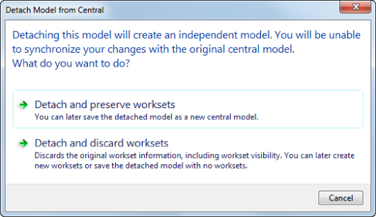
Figure 5.18 Detach Model From Central dialog box
Disabling worksets results, of course, in the loss of workset visibility. Unfortunately, some users utilize worksharing as a type of extended layer or visibility control. The trouble with this workflow is that the problem is exacerbated by the introduction of workset visibility control in view templates. Now there are six ways of turning off an object in a view in your project file:
- Visibility/Graphic Overrides
- Filters
- Design Options
- Phasing
- Worksets
- Hide Element
You can also control any linked file either in conjunction with your view settings or separately.
Project Phasing and Design Options
If an architect has an existing building and is developing new and future designs, that architect may have phases set up in the project file. You'll definitely need instruction from the architect on the particular phase of the project on which you are working, and what Phase filters were applied. Once you have a list of the phases in the architect's project and understand which ones apply to your contract, you can set up phase mapping.
Say the architect has Existing, New Build, and Interior phases. Your project has the phases First Fix and Second Fix. Select the linked Revit file, and from the Properties dialog box, select Edit Type. Then, in the Type Properties dialog box, select Phase Mapping, as shown in Figure 5.19.
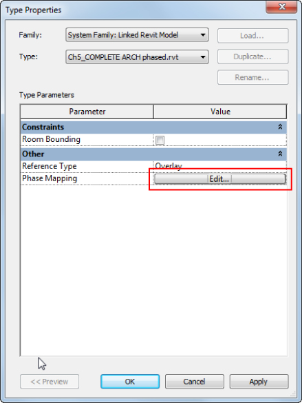
Figure 5.19 Linked file type properties
This is where you decide which phase in the architect's file corresponds to a phase in your project, as shown in Figure 5.20.
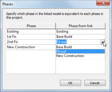
Figure 5.20 Phase mapping
Once this mapping is finalized, any views set up in your project specifically for First Fix or Second Fix will also display the architectural model correctly. (Notice the term model. This has no effect on any linked DWG files because phasing applies only to model objects.)
Hopefully, by the time it comes to the MEP design, most major issues, such as whether the building is square or rectangular, will have been sorted out. However, if the architect is still in discussion with the client, you will need to be prepared to discuss the primary design option with the architect and, if are you being paid to, design for that option plus the other options that the architect thinks the client may like.
But we've jumped ahead here! What about the MEP concept and preliminary designs? How do we as modelers and designers fit in with what the architect is designing? What are our responsibilities, and how much are we modeling and designing in Revit?
If we are relying on the architect to provide a model at the concept stage so that we can run analysis calculations for a building's heating and cooling loads, we really need an airtight model. Chapter 17, “Solid Modeling,” covers the merits of using the Mass Modeling tools in Revit to generate a building form.
Revit Family File
Revit families are the elements that bring any design to life. They hold data that, when created correctly, provides more than just a visible indication of an object's placement. Thus, team members should reach a consensus that Revit families are implemented to a certain standard:
- The appropriate family template file is used.
- Categories are set correctly.
- Subcategories are adequately and consistently named.
Within your company, you should have a standard for family creation. This standard could specify any of the techniques and best practices used in creating families that can be placed into your library.
Your standard should include items such as the following:
- Common Orientation and Insertion Points If a family is exchanged with another, you really don't want it to jump 2 feet to the left and rotate 22.5 degrees.
- Naming Conventions for Subcategories and Reference Planes This helps make the families perform as required in relation to visibility settings when loaded into the project. These conventions also aid users when familiarizing themselves with how best to create a family according to company standards.
- A Standard, Companywide Shared Parameter File
This ensures that families, even from different categories, can share the same type of data that can be reported, tagged, and scheduled in the project file. A great starting point for consistency is the Autodesk Revit Style Guide. It can be found at:
http://seek.autodesk.com/MarketingSolutionsRevitStyleGuide.htm
ADSK
The Autodesk Exchange File (ADSK) format covers multiple platforms. In its current format, which is XML based, ADSK allows the user to export from, say, the Autodesk® Inventor® platform to an ADSK file, which can then be imported into Revit. There is functionality in Revit Architecture to export ADSK files for use with civil engineers, although this is not supported in MEP. This is a static form, but it does have the benefit that, if connectors have been placed in Inventor, their properties are taken through as Revit MEP connectors. You can open ADSK files from the Open command, and after you save them, they become loadable Revit families.
IFC
The Industry Foundation Classes (IFC) file format was introduced as a solution to the problems of multiple software vendors competing in 3D space. IFC is an XML file format that can be edited in text editors such as Windows Notepad. Although the IFC format is somewhat limited from within Revit itself, Autodesk has made the IFC import/export tools open source (freely available to programmers) and the Revit API has been expanded with each release to offer greater support for getting data to and from IFC.
Using IFC can increase the number of consultants with whom you can interact. There is a potential downside, however. Unless you spend adequate time at the front end of the project discussing just how the data (format) is to be transferred with all parties, problems can arise from data that, when opened, is so inefficient as to be almost worthless. In some cases, it is preferable to use the import method as described in the previous exercise than it is to import an IFC file. On an average-size project, an IFC file can take literally hours to import, and then the objects that are imported might turn out to be in-place families.
The case study “Choosing the Right File Type” highlights some of the issues that users face when using the IFC format. At the time of this writing, numerous companies are producing free as well as fee-based IFC viewers, which allow the user to view the building model and any properties that are attached to the building elements. Some of these software vendors also provide IFC cleaners that allow for the optimization of an IFC file prior to opening it in any other suitable software.
AutoCAD DWG
As described earlier in this chapter, native AutoCAD and MicroStation files are easily imported or linked into Revit. The purpose of doing so in the 2D environment is that it can be a good way of bringing together a project team with a wide range of skills.
The reasons for importing native 3D objects from AutoCAD can be a bit blurred. If you were modeling 3D building objects in AutoCAD, why wouldn't you do the same in Revit? It could be argued that a company already has a wide range of 3D library components that may or may not need to be parametric, so what would be the harm in importing those objects into a family template of the correct category that is then saved as a loadable Revit family? There are mixed opinions about this, especially when companies have to invest substantially in extra development work. With the bottom line speaking louder than it has for many years, a lot of companies are preserving or reusing as much as they can, in the hope that doing so will save them money. At the end of the day, it comes down to economics, but (and point this out to your employer) invest wisely and spend the necessary time on developing or purchasing your Revit library. The alternative is reusing the existing 3D data, but this often has detrimental effects on the project: file size, excessive complexity, and appearance all play their part in slowing down your production.
DWGs from Verticals
AutoCAD verticals (such as Architecture, MEP, and Civil 3D) and Bentley Architecture are object based, relying on additional object enablers to create more functionality. This can lead to proxy objects, discussed earlier in this chapter.
The way AutoCAD or MicroStation handles this intelligent information is to give the user the ability to export to IFC. Exporting DWG/i.dgn elements to IFC does work. Sometimes you even get real building elements when this data is opened in Revit. However, exporting isn't perfect. Many times the data is all there but can end up as in-place elements, which can be inefficient.
SketchUp
There! We said it!
Yes, you can.
Why?
OK. OK! Say that someone has modeled the entire city block and surrounding suburbs in Trimble SketchUp and you can import that model, enabling you to perform sun studies. Later in the book, you'll see how to do exactly the same thing in Revit and have something useful in your project file.
Other File Formats
So, while these 3D elements can be imported into Revit, the latest functionality introduced to Revit 2015, as mentioned at the start of this chapter, is the ability to import files (for example, ACIS solids in the form of SAT format files), explode them, and retain the 3D elements. This lets you directly manipulate the 3D object because it is now a free-form object within Revit that can be manipulated, stretched, and cut with voids just like any other Revit solid object. This function has the potential to greatly help in the transition from one file format to another.
However, this new feature has some limitations. Although rectilinear objects can be stretched and manipulated using shape handles, any radii remain static, even though they can be dimensioned. Figure 5.21 shows two examples. On the left, an ACIS solid created in AutoCAD and imported into a Revit mass can be seen. Notice the grips on each face but no controls on the arc. On the right, a similar model has been imported from SketchUp. The main difference is the way SketchUp uses triangulated surfaces to create arcs.
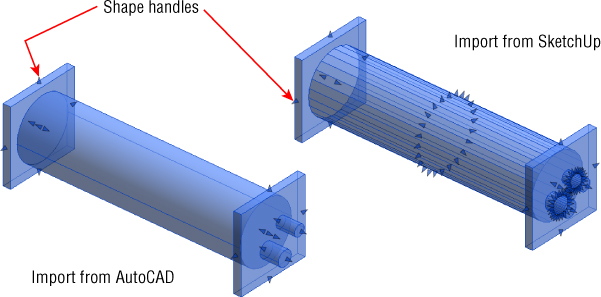
Figure 5.21 Imported ACIS solids
Point Clouds
Point clouds are beginning to be the new import for existing conditions. Obtain a laser scan of your building and it's a simple job to check design data against the As Built model. Revit supports a wide variety of formats (including PCG, which was the default file format in previous versions). In the 2014 release, the point cloud engine was changed to use RCP and RCS formats; the others must be processed on insertion into Revit. You can do this by selecting Raw Formats from the Files Of Type drop-down list, as shown in Figure 5.22.
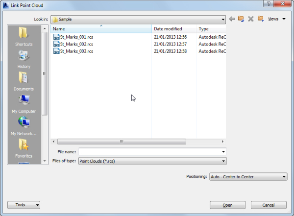
Figure 5.22 Selecting Raw Formats from the Link Point Cloud dialog box
These raw files need to be indexed, as shown in the message box in Figure 5.23. This process creates the native (RCP) files. Although the conversion may take a while, this indexing is performed in the background, so you can continue to work on other things.
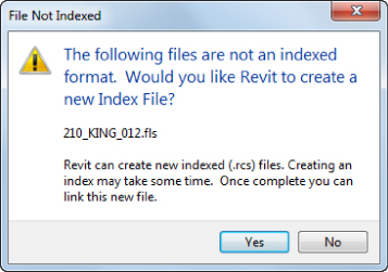
Figure 5.23 File Not Indexed message
Once the RCP file is created, it can then be linked into your Revit project in the same way as any other linked file. This type of new format is a great way to start an as-built project. This type of data is going to take up resources, however, with files starting at around 200 MB. Nonetheless, the indexed file performs well after it is linked. With the point cloud data linked, you can view it in the same way as any other linked file. In Figure 5.24, you can see this cropped 3D view, which is displaying suspended luminaires.
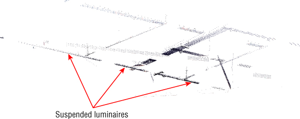
Figure 5.24 Cropped 3D view
The Bottom Line
- Decide which type of data you want to use on a project Revit 2015 allows the user to import and reuse existing drawings from AutoCAD and other formats.
- Master It Having a good command of the tools available for importing other file formats will extend and enhance the integration of Revit with other CAD systems. When importing a 2D file format into Revit, what are the two best ways of ensuring that the data is shown in only one view?
- Link data consistently and in the correct location When bringing data into Revit, it is important to be able to define where an object is positioned.
- Master It An imported drawing has inaccurately placed or frozen layer objects that make the extents of that file greater than 20 miles (32.2 km). What should you do prior to the import?
- Prepare data prior to import Revit project files should be the easiest to link to your project. However, at times this process can become complicated.
- Master It After receiving a Revit Architecture model, you can see that some worksets are causing visibility issues when the file is linked to the Revit MEP model. How can this be solved?