Chapter 9
Creating Logical Systems
Creating and managing systems is the key to getting the Autodesk® Revit® MEP 2015 software to work for you. Systems represent the transfer of information between families. They are available for any ductwork or pipework system type you may have in your model. Electrical systems are also a part of Revit MEP and are discussed in Chapter 14, “Circuiting and Panels.”
In this chapter, you will learn to do the following:
- Create and manage air systems
- Create and manage piping systems
- Configure duct connectors
Why Are Systems Important?
Systems are the logical connection between elements in the model. They are the link between the air terminal, the variable air volume (VAV) box, and the air handler, and they represent an additional layer of information above the physical connections made with ducts and pipes, the engineering information. Without systems, ducts and pipes act only as connections between two points. Systems are needed to generate the bigger picture and allow you to manage the elements on a building-wide level. Systems enable you to build more than just a three-dimensional model, they enable the engineering to be included in the model as well. You can create systems to represent supply, return, and exhaust air as well as plumbing, fire-protection, and hydronic piping. You can also create new system types to represent other uses of ducts and pipes outside the predefined types included in Revit MEP 2015.
Systems also aid in the documentation of a model. Because the systems link elements, and their engineering data, across the entire model, tags and other properties can be managed quickly and accurately. One example of this is using a pipe tag that includes not only the size but also the system abbreviation and, if needed, flow rate, velocity, or friction loss within the pipe. You can even set the temperature and fluid type for your system. Tagging any piece of pipe connected to the system, in any view, immediately generates a complete and accurate annotation.
Managing Systems
Managing systems is the easiest way to separate, say, a cold-water pipe from a hydronic pipe. If you can't separate the two, you will not be able to produce sheets showing certain systems and hiding others. As you draw a pipe or duct, Revit will automatically assign it to a system. If you are drawing pipe or ductwork from scratch, you can select the system type it will belong to from the Properties palette. If a duct system is created directly from the connectors of mechanical objects, the ducts assume the system of the host objects.
Even though the ducts are associated with a system, managing space air quantities has to be done externally. Entering all the information needed to accurately represent the mechanical systems in a building may seem like a daunting task at first, but the benefits of having all the information in one place and directly in front of the user can lead to more accurate designs. Instead of the user flipping between a building-load program and a duct-sizing chart (or wheel) and trying to keep track of which terminal box is serving which space, systems can handle all of that for the user. By feeding Revit MEP 2015 the load information, calculated internally or externally, and creating an air system for a space, the user can quickly determine the cubic feet per minute (CFM) required at each air terminal with a schedule or a custom space tag. The airflow will then be assigned to the terminal box, and the space that it is serving can appear in a schedule. One program can handle all of these tasks, which the user would have to do anyway.
Using connected systems can also improve performance for Revit. Even if systems are not being specifically set up, Revit is using systems behind the scenes to keep track of all the information in the model. You can enable or disable calculations per system type (Supply, Return, Exhaust, and so on), thus increasing the performance of the Revit model. To do this, select the Piping system from the Project Browser, right-click, and select Type Properties. All elements get assigned to their default system classification(s) (but not system types) based on the type of connector: supply air, return air, hydronic supply, and so on.
System Browser
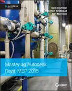
The System Browser, shown in Figure 9.1, summarizes all the systems currently in the model. If that were all that it did, it would be a useful design tool. You could keep track of all the air and water in the building and see your system totals at a glance. But the System Browser in Revit MEP 2015 takes this idea a step further; it is a live link to the components in the system as well as their parameters. You have full control to modify the airflows, equipment types, and diffuser selection, all from a single window.
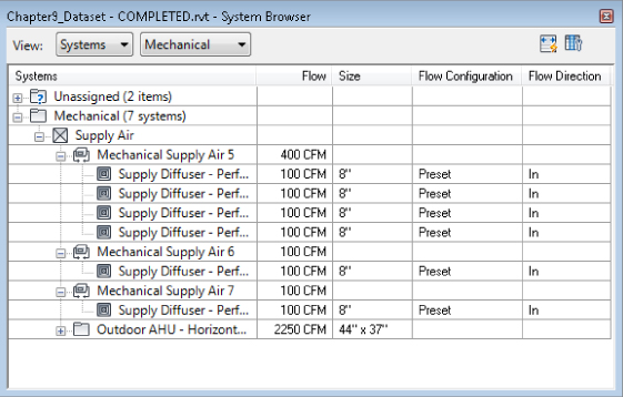
Figure 9.1 System Browser
You can access the System Browser from View ![]() User Interface
User Interface ![]() System Browser or the F9 function key. The system browser is directly linked to the elements in the model. Elements that have yet to be assigned to a system will be shown as Unassigned. This can be seen in Figure 9.2.
System Browser or the F9 function key. The system browser is directly linked to the elements in the model. Elements that have yet to be assigned to a system will be shown as Unassigned. This can be seen in Figure 9.2.
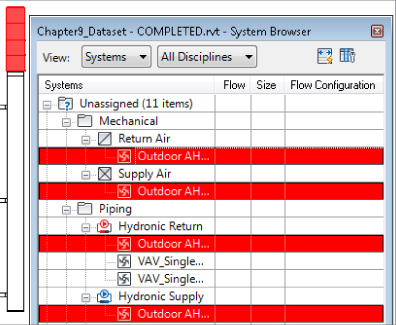
Figure 9.2 Examining unassigned systems and elements in the System Browser
In the System Browser, if you expand the system tree, you can see that when an object is selected, the corresponding item is highlighted in the drawing area. Conversely, selecting items in the System Browser highlights the objects in the drawing area, as long as the items are actually visible in that view. This is shown in Figure 9.3.
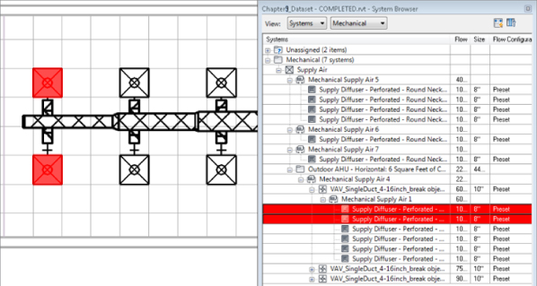
Figure 9.3 Selected elements in the drawing area highlighted in the System Browser
You can customize the system browser by setting up the columns it displays. The System Browser can get very large, so a second monitor is helpful. You can access the Column Settings dialog box by clicking the Column Settings button in the upper-right corner of the System Browser, which gives you an expandable list of the information that can be referenced in the model (see Figure 9.4).
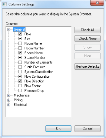
Figure 9.4 Column Settings dialog box
Obviously, not every parameter will be filled out for every part of the system, and some of the parameters will not be useful on a day-to-day basis. The columns you choose to display depend on your personal preferences and how you model your systems. For example, Space Number and Space Name populate only if the element and space touch. If spaces are bound by the ceiling, and terminal boxes exist above the ceiling, they will not be associated with a space. You have to use the Show command to find lost terminal boxes. To do this, right-click any element in the System Browser and select Show.
Ideally, every connection on every piece of equipment would be associated with a system, and the unassigned system category would be empty. This may not be realistic on a large job or where manufacturer content is being used. You may not need to model every condensate drain, but if the manufacturer has provided a connection point for it, there will be a listing in the System Browser. If your firm decides to use the System Browser to carefully monitor the systems and elements in the model, you may want to eliminate connectors that you will not be using to keep things clean.
To remove systems you must edit the family with the connector that is not being used. For more information on equipment families, see Chapter 19, “Creating Equipment.”
Mechanical Settings
Before you can jump in and start creating systems, you need to set up several things to ensure that the systems work as they should. There is nothing wrong with the default settings, but every firm is different—each has its own standards, procedures, and design requirements. Most companies have developed their own standards and endeavor to adhere to various industry standards, and these are good guidelines to follow when using a new application such as Revit MEP 2015.
The Mechanical Settings dialog box, accessed from the Manage tab's MEP Settings panel, contains some of the most critical settings for using systems in Revit 2015. This dialog box, shown in Figure 9.5, was briefly covered in Chapter 2, “Creating an Effective Project Template.” A more in-depth look is needed so you can understand how these settings affect systems in Revit 2015. All of these settings should be established in your company's project template. Changes to them should be discussed with the Revit team as well as the CAD manager, because data, visibility, and graphics can be dramatically affected by a minor change in this dialog box. Due to the specific nature of the information concerned, it is recommended that each discipline put an experienced person in charge of maintaining its own system settings.
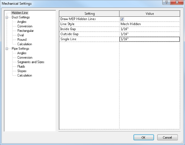
Figure 9.5 Mechanical Settings dialog box
Several settings really affect systems graphically. For example, by choosing Hidden Line, you see Inside Gap, Outside Gap, and Single Line. By default, each one of these is set to 1/16″ (1.5 mm). By changing the numeric size of each one of these parameters, you can get a different look that helps match your existing standards. We will look more closely at the Mechanical Settings dialog box separately for duct and pipe systems later in this chapter.
Setting Up Duct Systems
Before we can begin creating the system, we need to ensure that the duct and duct system settings are correct. Starting with the Mechanical Settings Dialog box we looked at earlier (Figure 9.5), expand Duct Settings and look at each section.
- Duct Settings Duct Settings allows you to customize annotation sizes, suffixes, prefixes, and size separators.
- Angles Here you can specify to use any angle, select an angle increment to be used, or select to confine the design to specific angles only.
- Conversion This section is for setting the standard Duct Type and Offset parameters for both main and branch runs, as well as the flex duct type and maximum flex length allowed. These are the settings that will be applied when the Generate Layout feature of Revit MEP is used.
- Rectangular, Oval, and Round In each of these you can specify the standard sizes for your ductwork, whether these sizes should appear in size lists, and whether they should be used by Revit when it is automatically sizing the ductwork.
- Calculation Here you can see the calculation Revit uses for its duct sizing, velocity, and pressure drop calculation. New to Revit 2015, you can now select between the original calculations (The Darcy-Weisbach equation used in the ASHREA handbook of fundamentals) and the Haaland equation (based on guidelines from the Chartered Institution of Building Services Engineers [CIBSE]).
Now we can look at the duct type properties. You can access this from the families section of the Project Browser. Select Duct and choose any duct type, right-click, and choose Type Properties. You can create new duct types by duplicating existing ones.
In this dialog box, apart from parameters listed under the Identity Data group, there is only the Roughness value to be changed; however, from here you can also access the Routing Preferences dialog box (see Figure 9.6). With Routing Preferences, you can apply a list of each fitting you wish to be used and leave out those you do not. For example, you may wish to use flanged fittings only. You can also set the preferred junction type (Tap or Tee), although it is always a good idea to include at least one tap and one tee connection in the junction list because often you will need both. Defining the routing preferences correctly is essential to enable efficient modeling of duct systems. For standard duct types used regularly within the office, the routing preferences should be set up in the template file. See Chapter 2 for more information.
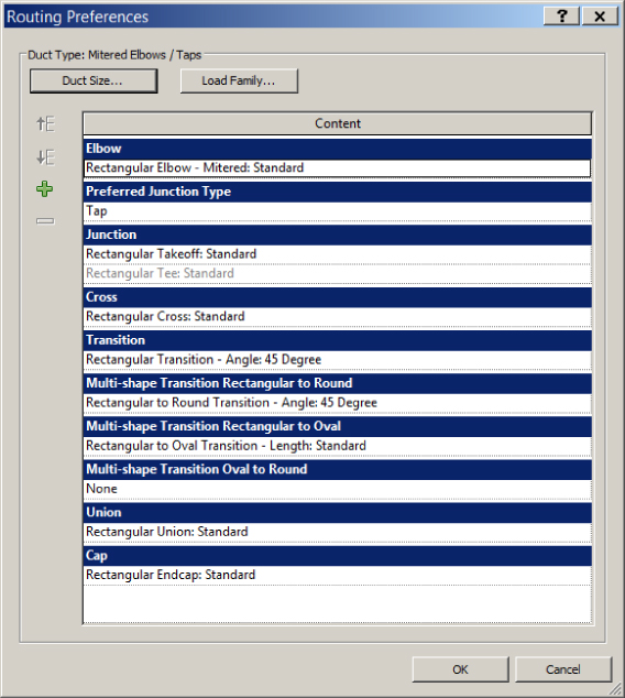
Figure 9.6 Routing preferences for ducts
The Routing Preferences dialog box also gives you the Duct Size button to open the Mechanical Settings dialog. You can load additional duct fittings with the Load Family button.
Now let's look at the Duct Systems dialog box. Like ducts themselves, you can access the duct system type properties from the Families section of the Project Browser. You can also access them by right-clicking the system type in the System Browser. The Duct Systems dialog box (see Figure 9.7) is where you can create new systems by duplicating existing ones. You must be careful to use the correct existing system categories to begin with so you can then connect to the correct points in your families.
- Graphic Overrides This is where you can set the color, line weight, and line pattern of each system for display purposes.
- Material Materials are primarily for rendering purposes, but they can be used for material takeoffs or as another method of filtering. However, applying a material to a system applies that material to the whole system, ducts, air terminals, and air handling equipment.
- Calculations You can set the calculations to All, Flow Only, or None. The more calculations allowed, the more powerful Revit 2015 and specifically the systems in it can be; however, this comes at a cost to performance. Which setting is used here is dependent on the project itself and the level of in-model calculations required. Remember that this setting can be changed at any time and it is probably best that it be set to None or at least Flow Only except for the specific times that all calculations are needed.
- System Classification The System Classification value is the original, or parent, system. This value, which is read-only, shows which type of connectors the system can connect into and is decided by the original system (Exhaust, Return, or Supply) that was duplicated to create the system you are working with.
- Type Image New to families in Revit MEP 2015, this provides the ability to set an image file that can then be used in schedules. For duct systems, this should probably be an image of the parent equipment for the system, that is, the VAV or air handler.
- Abbreviation This bit of data can be very useful because it can be tagged. Also, an abbreviation is neater on the drawing than using the entire system name.
- Type Comments As with comments, type comments can be useful for filtering or tagging that may be different for different systems in the project.
- URL Used to provide an external link for more information on the system.
- Description Used for descriptive information about the system.
- Rise / Drop Symbol Here you can specify which rise / drop symbol, from a fixed list of available symbols, to use for each system. Generally, supply air would be a cross and exhaust air would be a slash. Project or company standards will determine whether the symbols should be filled or if different symbols are to be used.
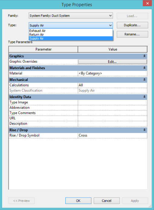
Figure 9.7 Duct Systems dialog box
Understanding Duct Connectors
Duct connectors in Revit MEP allow the user to connect ductwork to a family that may represent an air terminal, fan, VAV box, air handler, or chilled beam. Duct connections can also be used as a source for boiler combustion air and flues. There are many applications of duct connections beyond a simple supply air diffuser. In this section, you will learn how to set up many kinds of systems using duct connections.
You need a good understanding of the parameters besides height and width (or radius) needed in the connectors before you can set up air systems. There are 14 parameters associated with a duct connector when its system classification is not set to Fitting. Not all of the 14 are active all the time (see Figure 9.8). The standard Supply Diffuser that comes with the Revit install can be a good place to examine connectors.
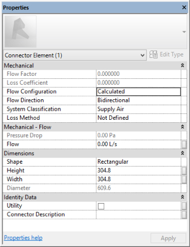
Figure 9.8 Parameters for duct connection
If the connector system classification is set to Fitting, the connector has only six parameters. Revit MEP has several system classifications available for duct connections that facilitate system creation and view filters within a project (see Figure 9.9).
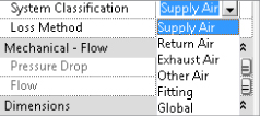
Figure 9.9 System classifications for duct connections
Starting at the top, here is an explanation of each duct connector parameter shown in Figure 9.8:
- Flow Factor This parameter determines the percentage of the system flow that will be seen by the connector. It is available only when Flow Configuration is set to System. It is useful when using multiple devices, each of which is sized for part of the load.
- Loss Coefficient Available only when Loss Method is set to Coefficient, this parameter is used in conjunction with the Flow parameter to determine the pressure drop.
- Flow Configuration This parameter determines how the connector flow will be calculated.
- Calculated This setting calculates airflow downstream of the connection and sets the Flow parameter to the sum of those flows. For example, a VAV Supply Air Outlet connector set to Calculated will add up all of the supply air requirements for connected supply air terminals that are using supply air connectors with a Preset flow configuration. In other words, child families using Preset will pass along their needs to the parent connector using a flow configuration of Calculated.
- Preset No calculation is needed, and airflow is set to the Flow parameter. This can be used for the inlet connector of VAV boxes.
- System This setting is similar to Calculated, but the flow factor comes into play. It is best used for splitting the total system airflow between air handlers.
- Flow Direction Flow Direction can be set to In, Out, or Bidirectional. This setting refers to the direction that air is moving relative to the connector, not the direction in which the air is flowing. For example, a supply air diffuser should be set to In because the air is flowing from the connected duct into the connector of the diffuser. An exhaust grille would be set to Out because air is coming out of the connector and entering the system.
- System Classification Here, the most appropriate system classification is chosen for the application. Supply Air, Return Air, and Exhaust Air are all pretty self-explanatory, but they also have other uses.
- Supply Air Air that is to be supplied to a space can also be used to model outside air, which is also known as air to be delivered to a space or air handler. Supply air would usually also be used for outside air.
- Return Air Air that is being returned from the space back into the system is called return air. It can also be used for relief air or transfer air, but exhaust can also make a good candidate.
- Exhaust Air Air that is destined to leave the space as well as the system is called exhaust air. There can be different types of exhaust air that you may want different systems for, such as, for example, Kitchen Exhaust, Toilet Exhaust, General Exhaust, and Smoke Exhaust.
- Other Air Other Air seems like a logical candidate for relief air or outside air; however, systems cannot be made with Other Air. In addition, if you want to utilize CFM calculations, you shouldn't use the Other Air system because it doesn't do those calculations.
- Fitting The Fitting system type is merely a pass-through connection; there is no effect on the airflow or definition of the system. However, fittings do affect pressure-loss calculations.
- Global Global connections can be either Supply Air, Return Air, or Exhaust Air. When you are creating the system in the project, you will be given the opportunity to select the type of system it should be. Fans are a good example of equipment that may use global connections because the same type of fan may be used in multiple system types.
- Loss Method
Not Defined, Coefficient, and Specific Loss are the options here, and Coefficient and Specific Loss each activate another parameter. Specific Loss should be used where the loss is known from a catalog or cut sheet. The pressure loss is taken literally as the entered value for Pressure Drop.
- Pressure Drop This can be entered as a static value or linked to a family parameter. Units are handled in the Project Units dialog box (Manage
 Project Units). Pressure Drop becomes active when Loss Method is set to Specific Loss. It can be linked to a family or shared parameter.
 - Flow Values for the flow associated with the connector are dependent on flow configuration. It can be linked to a family or shared parameter.
- Shape The Shape settings of Rectangular, Oval, and Round determine which dimension parameters are active and the shape of the duct that will connect to the connector.
- Height Height is simply a dimension of the connector. It can be linked to a family or shared parameter.
- Width Width is simply a dimension of the connector. It can be linked to a family or shared parameter.
- Radius/Diameter Radius/Diameter is similar to Height and Width. Previous to Revit 2014, you could only use the radius and not the diameter when linking to a family or shared parameter; however, since Revit 2014, under Dimensions in the Family Properties tab, there is an option to use either Diameter or Radius for the round duct connector. Whichever of these options are chosen, it should be made standard across the project to avoid confusion.
- Utility This indicates whether the connector is exported as a site utility connection or points to an Autodesk Exchange file (ADSK) for sharing with AutoCAD® Civil 3D®. It can be linked to a family or shared parameter.
- Connector Description The option to assign a name to connectors shows up primarily when using the Connect To feature. It also appears when connection points are in the same vertical plane. It is a good practice to give your connectors a description so that they can be easily identified in families with multiple connectors. It can be linked to a family or shared parameter.
Creating Mechanical Systems
Now that you have reviewed the parameters of the mechanical systems that exist, you will learn how to apply them in a simple exercise:
- Open the
Chapter9_Dataset.rvtfile found at www.sybex.com/go/masteringrevitmep2015. - Download the
Supply Diffuser - Perforated - Round Neck - Ceiling Mounted.rfafamily. Next, choose Insert Load Family, browse to where you have downloaded the family, and click Open (see Figure 9.10).
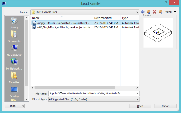
Figure 9.10 Selecting a supply diffuser
- Now download
VAV_SingleDuct_4-16inch_break object styles.rfalocated at www .sybex.com/go/masteringrevitmep2015, and insert it into your model (see Figure 9.11).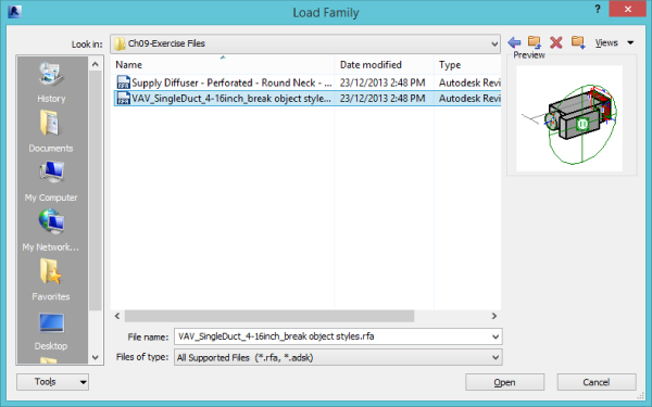
Figure 9.11 Loading a VAV single-duct family
- After downloading all of your components, you will want to place some diffusers onto the ceiling shown in the 1 – Ceiling Mech view. Because this family is a face-based family, it will automatically attach to the ceiling surface. Make sure to select Place On Face located under Modify | Place Air Terminal. If you don't, the diffusers will try to attach to the wall, or any vertical surface for that matter (see Figure 9.12).
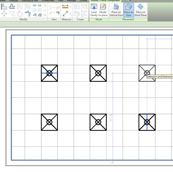
Figure 9.12 Placing the ceiling diffuser into the ceiling grid
- Once you have placed the diffusers, use the Mechanical Equipment tool on the Home tab to place the downloaded VAV box above the ceiling at an elevation of 10′-0″ (3 m). You can adjust the elevation by changing the elevation offset in the properties (see Figure 9.13). Set the elevation prior to placement if you are in a reflected ceiling plan view or you may not see the VAV box when it is placed.
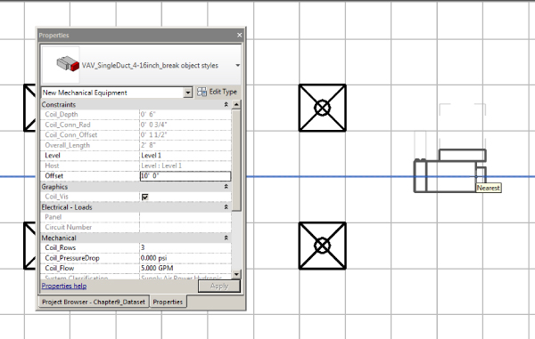
Figure 9.13 Changing the elevation offset for the correct elevation of equipment
- Now that the VAV box and diffusers are in place, make them part of a system. Select any diffuser and click the Duct button on the Create Systems panel of the Modify | Air Terminals contextual tab (see Figure 9.14). This activates a dialog box, shown in Figure 9.15, that allows you to choose the system type and to assign a name to the system. You can assign a system name if you wish, or you can leave it as the default name that Revit supplies. Note that, as these are supply diffusers, you can choose only system types that are also of a supply system category.
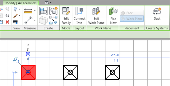
Figure 9.14 Creating a supply duct system
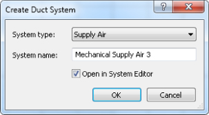
Figure 9.15 Create Duct System dialog box
- Once you have made the system by clicking OK, the Modify | Duct Systems contextual tab is active on the ribbon. Click the Edit System button. Confirm that Add To System is selected, and select the other air terminals (see Figure 9.16).
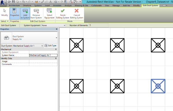
Figure 9.16 Editing supply duct systems
- Now click the Select Equipment button, and select the VAV box to be the equipment for your system. Click the Finish Editing System button to complete the system.
- With the system created, open the System Browser and select any of the diffusers. Notice that this selection also selects the appropriate diffuser in the drawing area. Now select the VAV as indicated in Figure 9.17. Notice that this also highlights Unassigned because the inlet to the VAV is not yet assigned to a system.
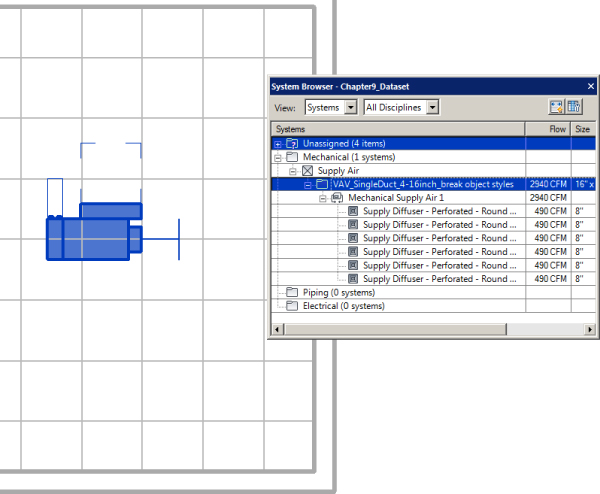
Figure 9.17 Selecting in the System Browser
Now that you have created your system, you can route your ductwork and it will take on the characteristics of the system parameters you set up. Understanding how to make mechanical systems enables you to create any duct system you may need for your design. For further instruction on how to route ductwork, refer to Chapter 10, “Mechanical Systems and Ductwork.”
You also have the ability to automatically create systems on the go as you route your ductwork/pipework. This means you don't need to create systems manually as in the previous exercise. Simply connect the supply duct to any diffuser and watch it become part of that system. But disconnecting the duct that “pushed” the system to the diffuser will not remove the diffuser from the system. Therefore, it will still be necessary to understand how to create and manage systems manually.
You can remove elements from a system using the Remove From System button when editing the system. You can also do this by right-clicking the connector symbol and selecting Remove From System. You can use either method only if the element is not physically connected to any other piece of the system (including ductwork). Once all elements have been removed from the system, the system itself will be removed from the Revit file. You can also delete the system from the System Browser. This will reset all elements in the system to Unassigned and set the ductwork to Undefined.
Setting Up Piping Systems
Mechanical piping benefits greatly from systems in Revit MEP 2015. Graphics, annotations, flow, and pressure loss can all be handled with a small amount of setup in your project template. Pipe systems also allow filters to apply to all components in the system, including the fittings. Also, the System Browser acts as a graphical pointer to the designer with regard to how objects are connected in systems; it also provides benefits in terms of how the actual systems perform.
The first of these benefits is the ability to predefine the system in which pipes (and ducts) are created, allowing layouts to be designed without the need to set up systems in the first place. This allows the designer to create hot-water (HW) and cold-water (CW) pipe runs with graphical filters already in place to display the different systems being created.
Second, this allows for different systems to be interconnected. In order to do this, you just need to specify which system you wish to use before placing each piece of pipe.
Figure 9.18 displays sanitary and vent pipe systems with the system Sanitary 2 selected. When you are working with multiple systems that are connected, a fitting, an accessory, or equipment is needed between the two pipes or ducts for the separation of the systems to work. When the system change occurs at an elbow or tee, all is good. However, when you want to change the system but continue the pipe/duct in the same direction as the original one, you need to use the Split tool to insert a coupling fitting so you can have two systems. Even though everything seems to work visually when you have multiple systems connected in such a way, it is only for graphical purposes. The reality is that the ducts/pipes will lose all the calculations such as flow, pressure drop, and so forth.
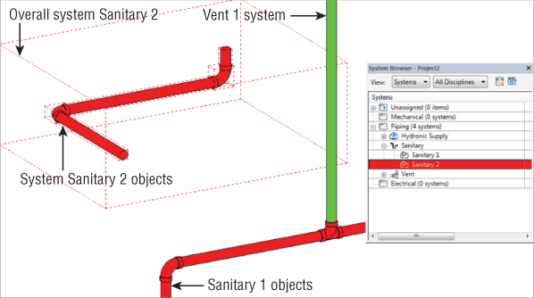
Figure 9.18 Dual-pipe systems
As the design progresses, systems may need to be merged with these new systemless systems. All the user has to do is connect the two systems. Figure 9.19 shows that after the two sanitary systems are joined, they effectively become one system with no further interaction required.
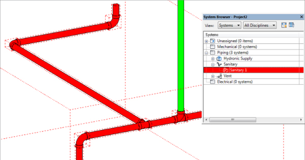
Figure 9.19 Merged systems
Understanding Pipe Connectors
Parameters required for piping connectors are similar to the parameters for air systems such as Flow Factor, Calculated, Preset, Flow Direction, and so on. The available pipe system types are as follows:
- Hydronic Supply This pipe system can also be used for chilled-water supply, cold-water supply, steam, hot-water supply, and process-piping supply.
- Hydronic Return This pipe system can also be used for chilled-water return, cold-water return, steam condensate, hot-water return, and process-piping return.
- Sanitary This pipe system can also be used for grease waste, oil waste, storm drainage, acid waste, contamination drainage, and condensate drainage.
- Vent This pipe system can be used for sanitary vent or any fume systems.
- Domestic Hot Water This pipe system can also be used for hot-water systems such as 140-degree (60°C), 110-degree (43°C), and tempered water.
- Domestic Cold Water This pipe system can also be used for filtered water, deionized water, and chilled water for remote drinking fountains.
- Other This pipe system can be one of the most utilized if you have a large piping project. This can be used for medical gas piping, vent piping, liquid propane piping, natural gas piping, and air piping, as long as they don't require flow or pressure calculations.
- Fire Protection This can be used for the building sprinkler piping, or it can be used for the utility fire protection coming into your building to connect the base of your fire-protection riser.
- Wet Fire Protection This pipe system type normally is used for the layout of the piping from the riser to the sprinkler head.
- Dry Fire Protection This pipe system is used for layout from the fire riser to the sprinkler head or standpipe to keep the system from freezing.
- Pre-Action This pipe system can also be used for a deluge system.
- Fire Protection Other This pipe system can be used for glycol antifreeze systems and for chemical suppression systems.
Creating Pipe Systems
There are several things to consider when setting up the components of a pipe system. You will need to define pipe types, load some fitting families, and create the necessary systems from the Project Browser by duplicating systems out of the box.
From the pipe type properties, you can assign routing preferences by size, as shown in Figure 9.20. For example, you may want to use a certain type of fitting only when routing pipes smaller than 6″ (150 mm) and another type of fitting for pipes larger than 6″ (150 mm). You may even want to choose different pipe segments (and therefore different materials) according to size, as shown in Figure 9.21. The pipe types should all reflect real-world values and the company standards and specifications. Even if you are not using Revit to size or lay out pipe automatically, not setting up the appropriate pipe types can cause headaches down the road because the Routing Preferences values still control which pipe fittings to use even if you are modeling the pipe manually. Pipe types should not be left at Standard and PVC. Those hardly cover the necessary piping systems that a building requires, and there will be fighting over what fittings should be standard and what materials should be used. Mechanical piping and plumbing piping should have their own pipe types. Even if exactly the same materials and fittings are being used, changes may arise, and splitting out pipe types late in a project will undoubtedly eat up a lot of time. This is one area of Revit MEP that enables you to have as many types as you want, so take advantage of it.
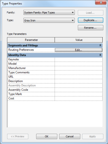
Figure 9.20 Pipe type properties
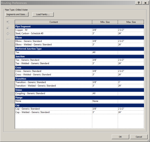
Figure 9.21 Routing preferences
Pipe segments and sizes are set up in the Mechanical Settings dialog box, shown in Figure 9.22. All of these settings should also be determined by using company standards and specifications and created using industry standards. It may seem tedious to set up, but if the inside diameter of a 6″ (150 mm) hot-water pipe is not correct, and you are using a lot of it, your pipe volume calculations can be skewed.
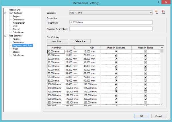
Figure 9.22 Pipe sizes
Fittings should be assigned after sizes and materials for a couple of reasons. First, the connection type needs to match. A solvent-welded PVC fitting and a flanged steel fitting are vastly different. Second, the fittings need to be defined at all the available sizes for that type of pipe; if it goes down to 3/8″ (10 mm) or up to 36″ (900 mm), the fitting needs to accommodate. Fittings are specific to the type of system, which is another reason to separate pipe types for plumbing and mechanical uses.
Hydronic systems have value even if the equipment is not piped together. Terminal box reheat coils are a good example because details generally cover their final connections. By simply adding all the terminal boxes to a hydronic supply and hydronic return system, you can see the total flows for the entire model. You can use this flow summation to ensure that systems are adding up to what you expect and to compare flows between systems. That's just another way of using the benefits of systems during early design, when not everything is connected yet.
Creating Fire-protection Systems
Fire-protection systems in Revit MEP are a sort of hybrid between air systems and hydronic systems. Sprinklers, from a system standpoint, are similar to air terminals. Sprinklers are designed to distribute a fluid evenly over a given area, with pressure as the driving force of distribution. In the case of fire protection, water is the fluid, and the fire pump or city connection provides the pressure.
The key to a good, manageable fire-protection system is the families. Decide what type of system you will be using, and make sure appropriate families are developed before you or other users start laying out components. Revit does have the ability to load a family in the place of another, but that tends to cause issues with system connections, pipe connections, and hosting. Sprinklers, standpipes, hose cabinets, and fire pumps may have to be created for the systems to work properly.
Setting Display Properties of Systems
Pipe systems are similar to duct systems, but they do have more parameters. These can be found in the piping systems Type Properties dialog box, as shown in Figure 9.23, accessed from the Families section of the Project Browser under Piping Systems.
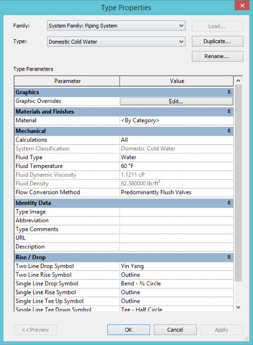
Figure 9.23 Piping Systems
The parameters for pipe systems start the same as for duct systems: you have Graphic Overrides, Material, Calculations, and System Classification. Then we get some specialized values. Which values are available depends on the system category.
Fluid Type, Fluid Temperature, Fluid Dynamic Viscosity, and Fluid Density are available only in Domestic Hot Water, Domestic Cold Water, Hydronic Flow, and Hydronic Return systems:
- Fluid Type Most of the time this will be water, and Revit MEP 2015 provides choices for Propylene Glycol and Ethylene Glycol; however, you can create other fluid types in Mechanical Settings for refrigerant systems or medical gases or any other fluid type you require.
- Fluid Temperature This is where you specify the temperature of the fluid.
- Fluid Dynamic Viscosity This value is determined by the fluid type and temperature previously selected. It does require that the correct values are entered when setting up fluids other than water.
- Fluid Density This value is determined by the fluid type and temperature previously selected. It does require that the correct values are entered when setting up fluids other than water.
Flow Conversion Method is available only in domestic cold and hot-water systems:
- Flow Conversion Method Here you have a choice of Predominantly Flush Valves or Predominantly Tank Valves. Your choice here will determine how Revit converts a Fixture Unit value to a Flow Rate for pipe sizing and pressure calculations.
The identity data is the same as for duct systems and the Rise/Drop parameters are similar to the parameters for duct systems but include both single line and double line options and Tee Up and Tee Down options.
Understanding Child and Parent Relationships in Revit Systems
To fully understand systems, there is one more thing you should know about: the child-to-parent relationships they must form in order to work properly. This knowledge is especially critical when you are building families. Without understanding the child and parent and their purposes, you likely will have problems with system flow and any sort of calculations using Revit.
Figure 9.24 shows an example of a supply air system and its child and parent relationships that must be formed.
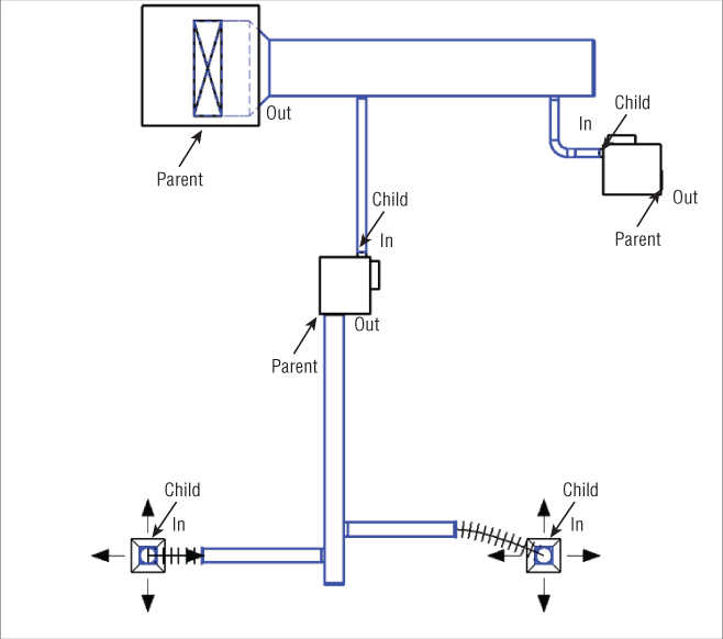
Figure 9.24 Children and parents in systems
There is a pattern in the child and parent formation. The system should always start with a child (for example, an air terminal) and end with a parent (for example, an air handling unit). The child will be a connector whose flow configuration is set to Preset. A flow configuration set to Calculate will be a parent. A flow configuration set to System can be a parent or an intermediary. For example, a chilled water system with multiple chillers will need system connectors to be able to divide the flow between them, and they will still be the parent. Pumps and fans use system connectors because they will split the flow into two or more paths, each with a pump/fan, and then recombine it into the single path before it continues on to the parent.
It is not the families themselves that are the child or the parent but rather the connectors within those families. Generally, the outlet of a VAV box will be the parent to the diffusers it is supplying, but the inlet will be a child of the primary air system. A heat exchanger would have inlets and outlets of both child and parent type. This can be confusing for the user and is a good reason to make sure the Connector Description parameter is filled out.
Flow direction is also important to enable systems to function correctly. The Flow Direction parameter for the connector of a supply air diffuser should be set to In (as the air is flowing from the system into the connector), and as such the parent for that system needs to have Flow Direction set to Out. If these are not set this way, the system cannot calculate the airflows because there is not a definite direction of flow along the duct.
Using System Filters
Mechanical engineering documents describe complex systems and design intentions. It is easy to overwhelm the person trying to understand those intentions. Revit filters offer us additional control over the visibility of certain elements in views as well as the appearance those elements will have (if you chose filters to control color and linetype). Without filters, we wouldn't be able to create sheets for the various subdisciplines—separating medical gas systems from plumbing and mechanical, for example. Filters help us create high-quality documentation as well as provide a better way to examine our design and improve the coordination of our projects.
To set up system filters, you can open any model view (plan, ceiling, elevation, section, and 3D are model views; nonmodel views are drafting views and legends) and type VG to access the Visibility/Graphic Overrides dialog box. Next, select the Filters tab and click Edit/New to open the Filters dialog box, shown in Figure 9.25. Notice that in this dialog box several filter names are in Revit by default. Remember that any changes made to filters after clicking Edit/New are global changes to the entire project, so adjusting filters should be left to the more experienced Revit users.
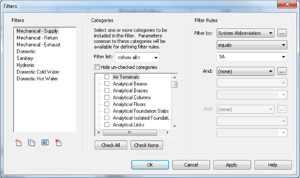
Figure 9.25 System filters
When you select any of the existing filters, certain categories have been selected. These are the categories for the items you want to have affected by the filter. Next, notice under Filter Rules that, by default, System Classification is selected. Because of the large number of filters typically created for a project, you should change the Filter By setting from System Classification to System Abbreviation. This helps identify and separate your systems properly.
If you try to use the default System Classification, soon you will find its limitations. The mechanical supply air system rule is set to System Classification to contain supply. This may not be a problem for small projects, but for larger ones that could have multiple supply systems, it won't work. This limitation is especially obvious when you have piping systems with numerous supply and return systems and distinguishing between all of them is critical. System Abbreviation has the necessary flexibility to allow for distinguishing hundreds of systems.
To create new system filters, the easiest method is to select an existing system filter and then click the Duplicate icon. After the system filter is duplicated, make sure the proper category elements are selected and then rename the filter rule to the name by which you want to filter.
When you are finished creating new filters or modifying existing ones, click OK to get back to the Filters tab in the Visibility/Graphic Overrides dialog box. Click Add. This brings up the filters that you have created, so select those that are needed in the current view of your project. After the filters are loaded, you can turn the filters on and off and adjust line weights, colors, and patterns, as shown in Figure 9.26. You can apply those filters to other views by opening a view, clicking the View tab on the ribbon, and then selecting Visibility/Graphics. Next, select the Filters tab.
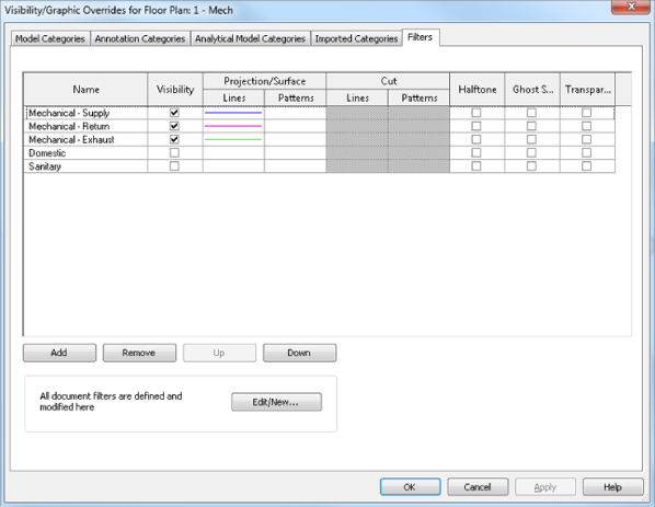
Figure 9.26 View filters
Mastering filter options enables you to create your models with the standards that your office has developed over years of producing CAD drawings.
The Bottom Line
- Create and manage air systems Knowing how to manage air systems can help productivity by organizing systems so that items can be easily interrogated to verify that the systems are properly connected.
- Master It True or false: Outside air cannot be modeled because there is no default system type from which to select.
- Create and manage piping systems By understanding how to change and manage piping systems, the user can create and maintain different systems effectively.
- Master It A designer has been asked by an engineer to create a Grease Waste system to accommodate a new kitchen that has been added to a project. What would be the quickest way to accomplish this feat?
- Configure duct connectors Everyone who needs to create Revit MEP families should know how to properly configure pipe, duct, conduit, and cable tray connectors in the Family Editor.
- Master It
In order to proceed with the design, a mechanical engineer needs to create a custom air handling unit family that is not available from the manufacturer. One of the challenges is that he has to configure the duct connectors for supply, return, and outside air. What are the proper settings for those connectors?
Hint: We already mentioned the proper configuration of the supply and return air systems in this chapter. The only oddball here is the outside air. This is the same kind of decision that will have to be made when creating systems such as fuel, medical gas, and so on that do not exist as a system classification in Revit.
- Master It