Chapter 11
Mechanical Piping
Mechanical piping is the lifeblood of a heating and cooling system. Incorrect piping can lead to problems in the field, and locating the pipes may take months. There are simple two-pipe systems and more complex multipipe systems. When using the Autodesk® Revit® MEP 2015 software to lay out your systems, you can easily see your routing options and even calculate the total volume of fluid in your system.
In this chapter, you will learn to do the following:
- Adjust the mechanical pipe settings
- Select the best pipe routing options for your project
- Adjust pipe fittings
- Adjust the visibility of pipes
Mechanical Pipe Settings
When setting up the mechanical piping to route, apply the proper pipe material. This provides a more accurate layout by showing the correct pipe sizes and fittings for that system. You have to adjust several areas to set this up properly. Most important are the piping systems and pipe types settings. You can also adjust pipe segments and sizes as well as the fluids table as needed. Each is described here in more detail. After you set up these areas, you can concentrate on the autorouting or manual routing of pipes.
- Piping Systems These are the pipe system types that are hard-coded into Revit projects and families. You have the options of creating new types, changing the names, and customizing the object styles for these system families within your project.
- Pipe Types This is where choices can be made regarding the fittings, segment types, and material for each pipe type. As you model with a selected type, these fittings, segments, and parameters automatically populate the pipe system and the model. The pipe fittings must be loaded into the project in order for you to select them in the Type Properties dialog box.
- Pipe Segments and Sizes These are set by choosing Mechanical Settings
 Segments And Sizes. You can select or duplicate a pipe segment, rename it, and apply the piping specifications for material, schedule/type, common sizes, and roughness of pipe walls.
 - Fluids Table You access the fluids table by choosing Mechanical Settings Fluids. You can duplicate, rename, and adjust the fluid type as well as its viscosity, temperature, and density.
- Slopes Table From the slopes table, you can preset the pipe slopes that will be used for the project. You access the slopes table by choosing Mechanical Settings Slopes. The list of slopes will be available when you are a drawing pipe with a slope.
- Angles From Mechanical Settings Pipe Settings Angles, you can choose whether the project can use any angles for pipe fittings or specific angles that are an industry standard.
Creating Piping Systems
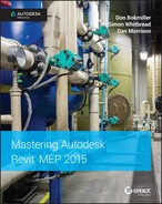
Piping systems are an essential part of designing piping layouts in Revit MEP 2015. They allow you to separate pipes from one another based on the function they are serving, the color and line pattern they should be displayed with, the fluid type they carry, and so on. The Piping Systems properties can be accessed and customized from Families Browser ![]() Piping Systems (see Figure 11.1).
Piping Systems (see Figure 11.1).
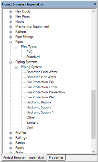
Figure 11.1 Accessing Piping Systems through the Project Browser
You can see the piping systems required in all projects in the Project Browser:
- Domestic piping systems (covered in other chapters):
- Domestic Cold Water
- Domestic Hot Water
- Sanitary
- Vent
- Fire-protection piping systems (covered in other chapters):
- Fire Protection Dry
- Fire Protection Other
- Fire Protection Pre-Action
- Fire Protection Wet
- Mechanical piping systems:
- Hydronic Return
- Hydronic Supply
- Other (You can't use any calculations for this option, so this option is appropriate only for systems that don't require calculations.)
Each of these items is what we call a system classification. System classifications are hard-coded in Revit, and you can't create new ones. However, you can create additional system types by right-clicking any of the existing piping systems in the Project Browser and selecting Duplicate. When duplicating piping systems, it is important to determine what the system classification should be and to select an existing piping system that is already assigned to that system classification. Once you create your piping system and realize that the system classification is incorrect, there is nothing you can do but delete it and start over with another one that has the correct system classification. In other words, system classifications have limitations: You are not allowed to change the system classification of piping systems or create or delete any system classifications. In addition, you must have at least one piping system for each of the 11 system classifications, and you cannot delete any of them even if you don't need them for your project.
Selecting the correct system classification can seem obvious for some system types—for example, chilled water is always going to be hydronic flow and return. However, lesser used systems can be more difficult—for example, medical gases and lab gases could fit into a number of different categories. It's essential to ensure that the system classification selected is then communicated to the entire team and used consistently throughout.
Each piping system can be assigned its own project-wide graphic override from within the system type properties (see Figure 11.2). This, combined with the ability to assign a segment of pipe to any of these piping systems without attaching it to a fixture or equipment, lets you improve the documentation produced earlier in the design process, when equipment families had not yet been built.
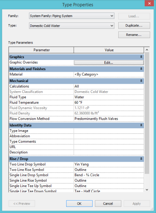
Figure 11.2 Properties for piping systems
One important drawback is that, because the linetype settings for piping systems are applied in all views, the common dashed-line patterns that are used with single-line pipe display (coarse or medium detail) will also dash the double-line pipe views (fine detail). For this reason, you can apply view filters to override any piping system graphic overrides. View filters are discussed in more detail later in this chapter in the section “Defining Systems Visibility through Filters.”
Creating Pipe Types
Pipe types are typically set up in your company template. They represent the level of detail that your pipes and pipe fittings should display. There are many approaches to organizing your pipe types; in this section, you will examine the most common ones:
- Exact materials and fittings as they would be installed
- Generalized materials and fittings
The first approach is to think of pipe types from the perspective of the installer. The pipe type is related to the material and style of fitting used. For instance, both chilled- and hot-water mechanical pipes, 3′ (900 mm) in diameter and under, are commonly constructed from copper with soldered or brazed sweat-joint fittings. This should be the basis of your pipe type. The benefit of this approach is a more detailed and accurate model. But the downsides can be overwhelming as well. Many systems could vary in materials and fittings, and the engineers may or may not know the material for the system at the time of modeling. And of course, in some cases, having too many material choices and fittings can overwhelm even the most knowledgeable modelers. This is a significant challenge when a company wants to target a high-detail level of the BIM model, but at the end of the day it would accomplish only what the person behind the computer is capable of. And in this case we are not talking about computer skills but engineering knowledge.
The second approach is to simplify things a bit and create pipe types that would cover more real-world systems under a single pipe type—for example, Gravity and Pressure. The gravity pipe type can be used for systems such as waste, grease waste, storm drain, and overflow leader. Pressure can be used for domestic hot water, domestic cold water, hydronic supply, hydronic return, and glycol. The limitations of this method are less-accurate models and volumes of the individual systems. Perhaps a combination of the two can be considered: generalization could be applied to most systems, except those for which volume calculations or the real size of fittings is of significant importance.
To modify and create new pipe types, in the Project Browser choose Families ![]() Pipes
Pipes ![]() Pipe Types and then right-click the Standard type. Select Duplicate. This creates the additional pipe types you will need for your project. Next, right-click the duplicated pipe types and rename them to the pipe types you require. It is preferable to rename them to the pipe material type selected under Pipe Segment. You can find out or change the pipe material under the Pipe Segment selection by right-clicking the pipe type and choosing Type Properties
Pipe Types and then right-click the Standard type. Select Duplicate. This creates the additional pipe types you will need for your project. Next, right-click the duplicated pipe types and rename them to the pipe types you require. It is preferable to rename them to the pipe material type selected under Pipe Segment. You can find out or change the pipe material under the Pipe Segment selection by right-clicking the pipe type and choosing Type Properties ![]() Routing Preferences.
Routing Preferences.
Now that you have created your pipe types, you will want to change some of the parameter options. First, start the Pipe command and click Edit Type from the Properties palette. This opens the pipe type parameters. With regard to careful space planning, the accurate selection of fittings is the most important and most time-consuming task when setting up your pipe types.
Revit MEP 2014 introduced an improved pipe Type Properties dialog box with access to Routing Preferences settings (see Figure 11.3). In the past, you could assign only one elbow or tee family per pipe type; now you have the option to set different fittings based on the pipe size you are drawing (see Figure 11.4). You can also designate different pipe segments at different sizes. For example hydronic piping (whether chilled, condenser, or heating water) may be copper up to about a size of 4″ to 6″ (100 to 150 mm) and be carbon steel pipe above that size. If you are going to designate different pipe segments, you must also make sure you set the fittings accordingly at the same sizes.
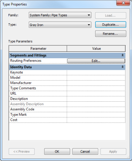
Figure 11.3 Type Properties dialog box
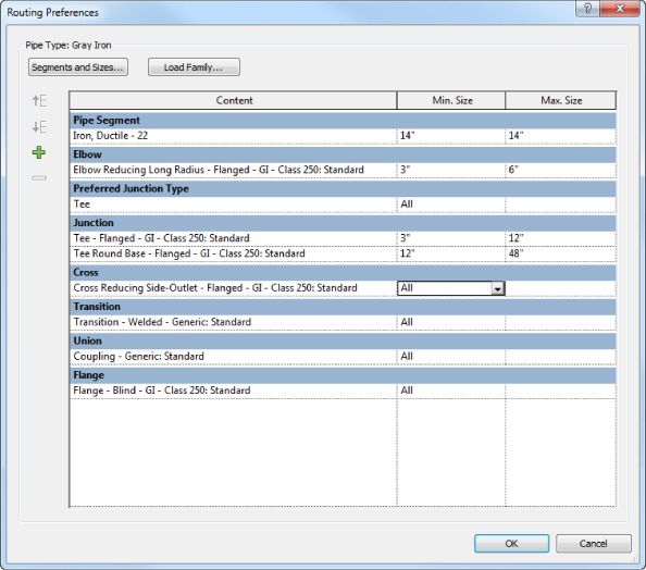
Figure 11.4 Routing Preferences dialog box
Under the Identity Data parameters group in the Type Properties dialog box, the following parameters are available: Keynote, Model, Manufacturer, Type Comments, URL, Description, Assembly Description, Assembly Code, Type Mark, and Cost. If you have a certain manufacturer, model, or other special note that you want to denote on the plans, you can use these settings to describe your pipe type further.
Defining Fitting Angles
From Manage ![]() MEP Settings
MEP Settings ![]() Mechanical Settings (see Figure 11.5), you can allow the user to use any angle, allow an angle increment to be used, or predefine the angles of pipe and duct fittings that Revit can use when you are laying out piping. When you are drawing pipes, Revit still displays all angles in their temporary dimensions, but once you click to finish the pipe, the created elbow is rounded to the closest angle you have allowed from the Angles settings. This can enforce the use of industry-standard angles, thus ensuring the use of cheaper fittings for the project instead of custom angle fittings, which usually come at a premium price.
Mechanical Settings (see Figure 11.5), you can allow the user to use any angle, allow an angle increment to be used, or predefine the angles of pipe and duct fittings that Revit can use when you are laying out piping. When you are drawing pipes, Revit still displays all angles in their temporary dimensions, but once you click to finish the pipe, the created elbow is rounded to the closest angle you have allowed from the Angles settings. This can enforce the use of industry-standard angles, thus ensuring the use of cheaper fittings for the project instead of custom angle fittings, which usually come at a premium price.
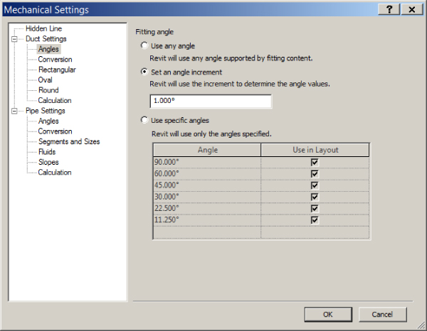
Figure 11.5 Pipe fitting angles
Selecting Fittings for Routing Preferences
Before you can adjust the routing preferences, you need to create the fittings that will go with your system pipe types. To accomplish this, open the Family Browser and choose Pipe Fittings. Then select the fittings that will be required for your Pipe Type parameters. You can either load the appropriate family from the Autodesk library or download manufacturer-specific fittings.
One noteworthy option that is missing from the fitting parameters is a pipe spud. To date, Autodesk has not included this pipe fitting family with its content. However, several pipe spud families can be downloaded from the Internet. If you would like to use one in your Steel-Welded pipe type, you first have to load the family into your project. Next, duplicate your pipe type and rename it Steel-Welded-Tap. It is critical that you have a separate pipe type because the Preferred Junction Type fitting parameter is set here. Change it to Tap, set Tee to None, and set the Tap parameter to Pipe Spud (the name of the family you have downloaded or created). Now you will be able to easily choose whether to model pipe with tee fittings by selecting the pipe type Steel-Welded or to model with spud-style tap fittings by selecting Steel-Welded-Tap.
Choosing Pipe Materials and Sizes
To access the pipe material settings, choose Systems ![]() Plumbing & Piping and then select the small arrow in the lower-right corner of the ribbon panel. This opens the Mechanical Settings dialog box. (Alternatively, choose Manage
Plumbing & Piping and then select the small arrow in the lower-right corner of the ribbon panel. This opens the Mechanical Settings dialog box. (Alternatively, choose Manage ![]() MEP Settings
MEP Settings ![]() Mechanical Settings.) Next, choose Pipe Settings
Mechanical Settings.) Next, choose Pipe Settings ![]() Segments And Sizes. If you want to create a new pipe segment, you can duplicate an existing pipe segment and rename it (see Figure 11.6). From here you can also change the Roughness setting and segment description or create a new pipe size.
Segments And Sizes. If you want to create a new pipe segment, you can duplicate an existing pipe segment and rename it (see Figure 11.6). From here you can also change the Roughness setting and segment description or create a new pipe size.
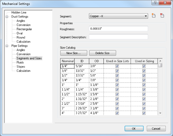
Figure 11.6 Creating new segments and sizes
Adjusting the Pipe Sizing Table
If you want to adjust the sizing table, choose Systems ![]() Plumbing & Piping, and select the small arrow in the lower-right corner of the panel to open the Mechanical Settings dialog box. Next, choose Pipe Settings
Plumbing & Piping, and select the small arrow in the lower-right corner of the panel to open the Mechanical Settings dialog box. Next, choose Pipe Settings ![]() Segments And Sizes. You can duplicate the schedule of pipe and apply the pipe wall thickness as required. You can also select and deselect the piping sizes to match your design standards (see Figure 11.6).
Segments And Sizes. You can duplicate the schedule of pipe and apply the pipe wall thickness as required. You can also select and deselect the piping sizes to match your design standards (see Figure 11.6).
Using the Fluids Table
Revit MEP uses the fluids table when you are sizing your pipes or determining pressure drop. You can add information concerning temperature, viscosity, and density to the fluids table. To do this, choose Systems ![]() Plumbing & Piping, and select the small arrow in the lower-right corner of the panel to open the Mechanical Settings dialog box. Next, choose Pipe Settings
Plumbing & Piping, and select the small arrow in the lower-right corner of the panel to open the Mechanical Settings dialog box. Next, choose Pipe Settings ![]() Fluids. Then duplicate one of the fluid categories that is close to the one you need, and modify it as required (see Figure 11.7).
Fluids. Then duplicate one of the fluid categories that is close to the one you need, and modify it as required (see Figure 11.7).
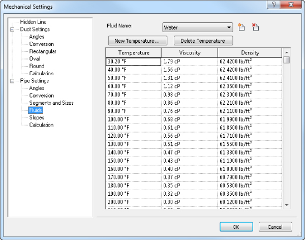
Figure 11.7 Fluids table settings
Pipe Routing Options
The size of a mechanical piping model can grow quite large because of the amount of fluids constantly transferred, so it is very important that routing is closely coordinated. Using Revit MEP 2015, you can improve visual coordination with color-coded systems and use interference checking to monitor conflicts with cable trays or sprinkler piping. Two routing options are available when you set out to design your piping model: the autoroute option and the manual routing option. Both are described in this section.
In smaller systems, the autoroute feature may be beneficial. However, in most circumstances, manual routing will be of greater benefit. This is because a good design engineer can optimize a system with regard to construction of pipe and coordination with other trades, especially structure.
Automatic Pipe Routing
Ideally, you have everything set up in your pipe types before you begin routing piping. To start automatic pipe routing, first assign your equipment to a piping system. Select two or more pieces of mechanical equipment, and from the Modify | Mechanical Equipment tab, click Create Systems ![]() Piping (see Figure 11.8a) and then name your piping system (see Figure 11.8b).
Piping (see Figure 11.8a) and then name your piping system (see Figure 11.8b).
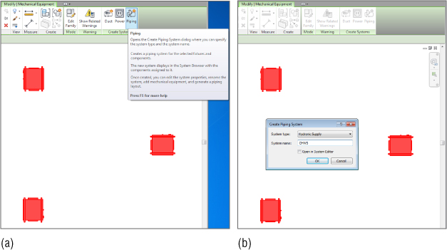
Figure 11.8 Creating your piping system
Next, select any piece of equipment assigned to the system and click the Generate Layout button. You have four options for generating the layout: Network, Perimeter, Intersections, and Custom. Each one has several routing solutions from which you can choose, consisting of a main pipe route (blue) and branches (green):
- Network This solution creates a bounding box around the components selected for the piping system and then bases several solutions on a main segment along the centerline of the bounding box with branches coming from the main segment.
- Perimeter This solution creates a bounding box around the components selected for the system and proposes several potential routing solutions. You can specify the Inset value that determines the offset between the bounding box and the components. Inset is available only when the Perimeter option is selected.
- Intersections This solution bases the potential routing on a pair of imaginary, perpendicular lines extending from each connector for the components in the system. There are potential junctions in the proposed solutions along the shortest paths, where the lines from the components intersect.
- Custom This solution becomes available after you begin to modify any of the other solutions.
The autoroute feature is most useful in small, simple layouts. Usually, the greatest benefit comes from using the autoroute pipe as a starting point and finishing with the additional manual layout. You can set the mounting height by clicking the Settings button from the Options Bar and inputting a new offset. Make sure to define the offset for both Main and Branch, as shown in Figure 11.9. When you're working with the autorouting command, several factors can affect the outcome—incorrect configuration of connectors, settings conflicting with the proximity of the equipment, elevation of the main pipe route and the branches, selecting flex duct type to be used, and so forth. For optimal results, have a plan view and a 3D view tiled to provide the most feedback about the final layout.
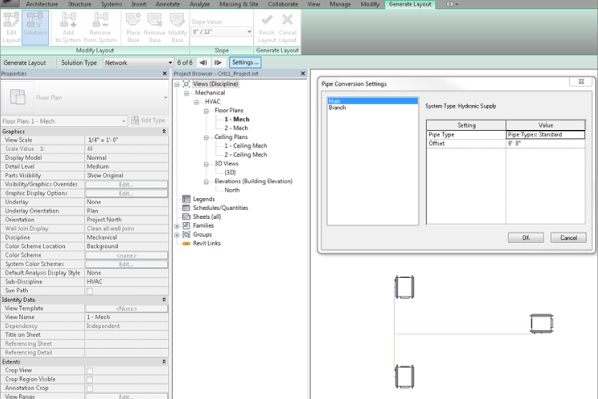
Figure 11.9 Autoroute piping layout
Manual Pipe Routing
When you are modeling pipes in Revit, develop good habits at configuring all the necessary settings while in the Pipe command. This is especially valid for inexperienced Revit users. Developing good modeling habits will serve you in the long run. Don't rush yourself. Take your time to confirm that all the settings are properly configured before you even draw the pipe. Some of the settings to pay attention to are Diameter and Offset from the Options Bar; System Type from the Properties palette; and Justification, Automatically Connect, Inherit Elevation And Size, Slope Off, Slope Up, Slope Down, Slope Value, and Tag On Placement, all available from the ribbon. You see that there are lots of settings to control, and they will certainly affect the outcome. So take your time to develop good habits when you are just starting with Revit.
When routing, manually start the piping run at the elevation that you know will most likely be out of the way of other disciplines. Use the following steps to set up and place mechanical equipment, create a hydronic supply and return, and manually route pipe to all pieces of equipment:
- Open the
Ch11_Project.rvtfile found at www.sybex.com/go/masteringrevitmep2015. - One of the best practices is for the architectural model to be linked into the mechanical model. Download the model
C11_base.rvtfile found at www.sybex.com/go/masteringrevitmep2015. - Choose Insert Link Revit, select the directory into which you downloaded the Revit base, select Auto – Origin To Origin from the Positioning drop-down, and then select Open. By selecting Origin To Origin, you are assured that the model will be properly located (see Figure 11.10). Open the default 3D view {3D}, to review the architectural model.
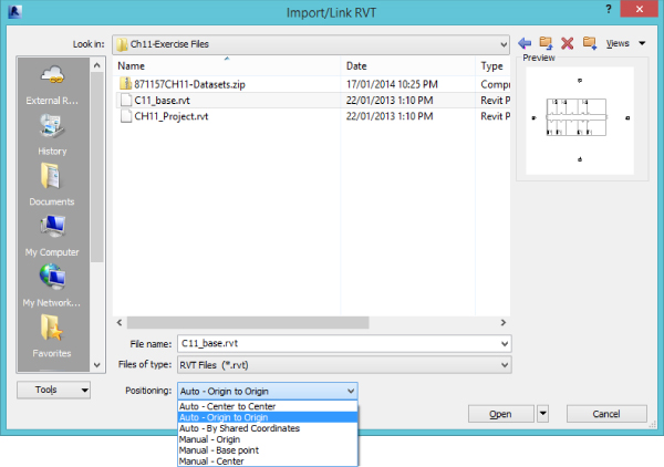
Figure 11.10 Linking the Revit model, Auto – Origin To Origin
- Open the North Elevation and, from the Collaborate tab, click Copy/Monitor, pull down and click the Select Link choice, and then move the mouse over any architectural element to select the linked file and enter Copy/Monitor mode.
- Click the Options button. For Reuse Matching Levels, choose Reuse If Within Offset and click OK. This ensures that your existing levels and floor plans will be reused instead of creating duplicates.
- While still in the Copy/Monitor tool, select the Copy command to copy Level 1 and Level 2, and then click Finish.
- Open view 1 – Mech. Download the file
WSHP - Horizontal.rfafrom www.sybex.com/go/masteringrevitmep2015. Choose Insert Load Family. Select WSHP - Horizontal.rfafrom where you saved it and then click Open (see Figure 11.11).Note that this is a standard Revit file that is included within the U.S. Imperial Content library, and as long as U.S. Imperial Content has been loaded with Revit, the file can also be found at Insert
Load Family Imperial Library Mechanical MEP Air-Side Components Heat Pumps.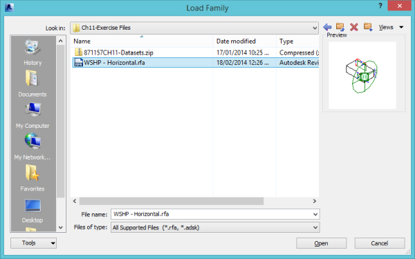
Figure 11.11 Water source heat pumps
- Choose Systems Mechanical Equipment, and start placing the water source heat pumps (type 006) into each room. If needed, you can use the spacebar before placing the equipment to rotate it 90 degrees. After you have placed all the heat pumps into the model, right-click the water source heat pump you first placed and choose All Instances Visible In View. Then, in the Properties palette, change the Offset parameter to 9′-0″ (2,750 mm). This will allow you to set the correct elevation of equipment (see Figure 11.12).

Figure 11.12 Verifying the offset for the correct elevation
- Your system will require a fan coil unit and a closed-circuit cooling tower. Both families are already loaded into your project. Place them into the appropriate locations, as shown in Figure 11.13.
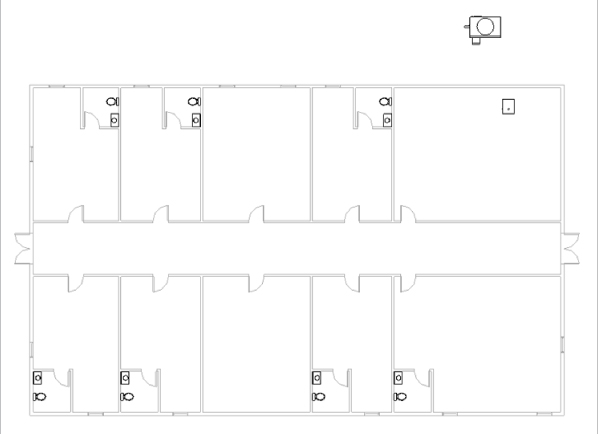
Figure 11.13 Placing mechanical equipment
- Next you need a centrifugal pump. Choose Insert Load Family Imperial Library Mechanical MEP Water-Side Components Pumps. Select
Centrifugal Pump - Horizontal.rfaand then click Open. Place the pump where you want it to be located in the mechanical room (see Figure 11.14).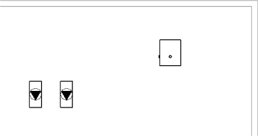
Figure 11.14 Placing the pump in the mechanical room
- You are now in a position to start routing piping. Route your mains first so you can make sure that most of the piping will fit before connecting all the branches to the mains. Select the proper piping material before starting your layout. This will help if you need to do a quantity takeoff for budgeting purposes. To route your pipe, choose Systems Pipe. Change the Offset parameter to 8′-6″ (2,600 mm) and Pipe Size to 2″ (50 mm); also make sure to select the pipe system type and route piping mains in the corridors and into the mechanical room (see Figure 11.15).
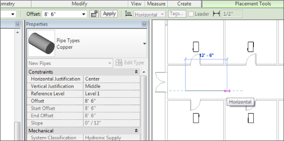
Figure 11.15 Routing pipe mains
- Before you start connecting piping, you will need to make sure that your mechanical equipment is set up for both hydronic supply and return systems. To do this, select one of the pieces of mechanical equipment, and then choose Modify | Mechanical Equipment Piping. In the System Type list box, select Hydronic Return, as shown in Figure 11.16.
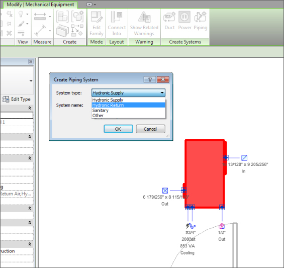
Figure 11.16 Creating mechanical piping systems
- After you have selected the hydronic return, go to the Edit Piping System tab, select Edit System, and edit the Hydronic Return system name. Then select Add To System (see Figure 11.17), and select all mechanical equipment that contains Hydronic Return connections. Repeat with Hydronic Supply.
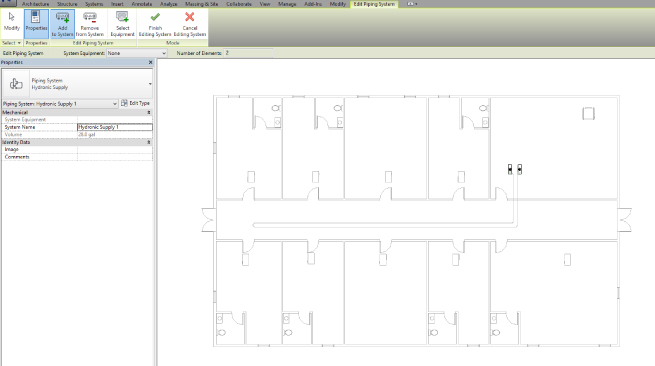
Figure 11.17 Adding equipment to systems
- Cutting sections when routing piping can really improve the coordination success of your Revit model. If you want to automate things a bit, instead of drawing all the pipes yourself, you can select any equipment with pipe connectors, select Connect Into from the Modify | Mechanical Equipment tab, shown in Figure 11.18, and then select the equipment connector you want to connect to an existing pipe (see Figure 11.19).
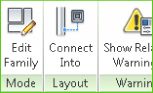
Figure 11.18 Selecting Connect Into
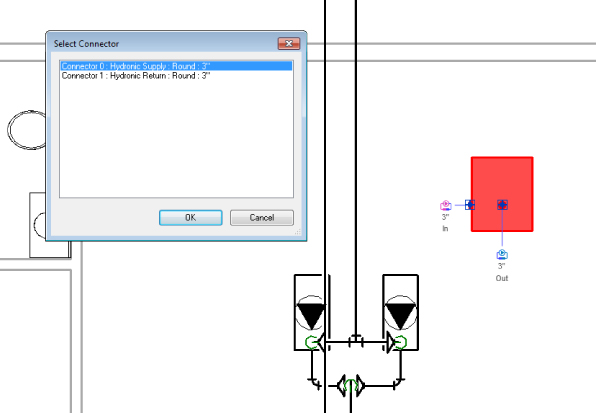
Figure 11.19 Using Connect Into
- Repeat steps 6 through 13 for all your piping systems. Taking a few minutes to review any clashes between the structure, mechanical, and architectural models can really cut down on potential field conflicts. After you have coordinated with other services/structures and verified your layout, the layout will be complete.
Pipe Fittings
Without fittings, piping would not be worth a whole lot. Fittings help shut off the flow, help regulate temperature, and help save lives. In Revit, most fitting families have the following functions:
- End Cap These can be placed only at the end of pipes.
- Tee, Tap, Wye, or Cross These can be placed anywhere along pipe runs.
- Transitions, Couplings, or Unions These can be placed only at the end of pipes. They are used to join a smaller, larger, or same-sized pipe.
- Flange These can be placed at the end of pipes or face to face with another flange.
Using Pipe Fitting Controls
Understanding pipe fitting controls can really make life easier if you are routing a lot of piping. When you are laying out your piping, turn 90 degrees to create an elbow. If you click the elbow, you will notice a plus (+) sign. If you click that sign, it will change from an elbow to a tee, allowing you to add more piping and continue your pipe routing. If you click the minus (–) sign, it will downgrade the fitting. When you see the ![]() symbol on a fitting, it allows you to rotate the fitting, and the
symbol on a fitting, it allows you to rotate the fitting, and the ![]() symbol allows you to flip the fitting.
symbol allows you to flip the fitting.
The display of both fittings and valves can be challenging as you rotate the elements to represent the actual needed position. In some cases, they may become invisible. For example, when you place a valve in plan view at either coarse or medium detail level, you will see its symbolic representation, but if you go to a section, you won't see the valve at all. However, if you change it to fine detail level, you can see the geometry of the valve. This is because the valve is displayed as a symbol when showing single-line pipes, and with all of its 3D modeled geometry when in double-line pipe views. Currently the symbol can be displayed in only two opposite views (two sections, or floor plan and ceiling—in all other views it will be invisible). This is a known limitation with Revit, and to avoid it you should consider developing a standard for displaying valves and fittings, and at a certain level of detail.
Placing Valves
When you need to add valves to your piping, select the System tab and then select Pipe Accessory. Use the Type Selector to select the type of valve you want to use. Most valves are break into types, so you can place them into a pipe run and they will break into the piping, maintaining connections at either end (see Figure 11.20). This behavior works even when you remove the valve: The pipes automatically fill in the gap where the valve used to be.
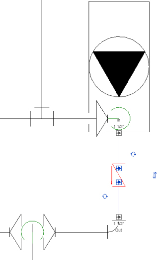
Figure 11.20 Valve breaks into a piping system
For some logical family categories, you can set this break into functionality in the Family Editor; choose Create ![]() Properties
Properties ![]() Family Category And Parameters (see Figure 11.21).
Family Category And Parameters (see Figure 11.21).
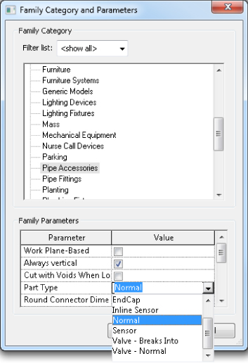
Figure 11.21 Defining Breaks Into behavior
Adding Piping Insulation
Certain pipes require insulation. In some cases, this may be accomplished by simply annotating the insulated pipe, but in other cases you may need to model and display the pipe insulation. Pipe insulation in most cases is required when pipes are displayed as double lines. Currently, in order to place pipe insulation in Revit, the pipes need to be laid out already. You can do that by selecting individual pipes or entire runs of pipes and fittings and using the Add Insulation command under Modify | Pipes (see Figure 11.22). Pipe insulation visibility can further be controlled from the Visibility/Graphic Overrides dialog box and Object Styles, like any other Revit category. Once insulation has been added, it cannot be selected straight from the model. Rather, select the duct pieces and then click the Edit Insulation button.
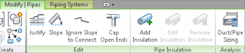
Figure 11.22 Adding pipe insulation
Defining Systems Visibility through Filters
Revit MEP 2015 automatically creates logical piping systems for you when you lay out pipes, even when pipes are not connected to equipment. When drawing pipes, you need to specify the system type they belong to. The system type can define the line weight, linetype, color, and system abbreviation. The system abbreviation can be used to define what system will appear on what sheet via filters. This helps you hide the mechanical pipes in the plumbing views, and vice versa.
Establishing a good naming convention for the filters is important, because that would be the order in which you see them in your Properties palette when drawing pipes. The default examples of filters and their settings are not going to get you too far with your projects. We recommend that you take your time and come up with a complete list of systems that your company uses and create them as system types and filters in Revit MEP. Organizing all of them in Microsoft Excel can be very beneficial! Notice that the Filter By setting is set to System Abbreviation Equals AV, as shown in Figure 11.23. Bear in mind that the parameter System Abbreviation was not available prior to Revit MEP 2012, and the settings would be different for those projects and templates. To create new filters, simply click the New button in the lower-left corner.
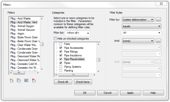
Figure 11.23 Sample filters and their settings
Once the filters have been created, go into each view where you want the different disciplines to show up and type VG to bring up the Visibility/Graphic Overrides dialog box. Click the Filters tab, and add the newly created filters. If the view is controlled by a view template, then you must do this through View ![]() View Templates
View Templates ![]() Manage View Templates. Using the Visibility check boxes on the Filters tab, you can define the systems to be visible in that view. In the past, filters were used to also define color, line patterns, and in some cases line weights. Since Revit MEP 2012, the recommended place to control those is in the System Type settings for the pipe. This way, those settings will be global rather than per view. However, the filters would still be managed and would control what system is visible in what view (see Figure 11.24), and they would still control line patterns, color, and line weights for specific cases. An example of this would be when you are using a 3D view. When you control the colors and line patterns of your systems in the 3D views, it will color the contour of the pipe, making the pipes hard to see. You could then override those in the filters with a solid pattern; this way, your 3D views would be a lot easier to view and understand (see Figure 11.25 and Figure 11.26).
Manage View Templates. Using the Visibility check boxes on the Filters tab, you can define the systems to be visible in that view. In the past, filters were used to also define color, line patterns, and in some cases line weights. Since Revit MEP 2012, the recommended place to control those is in the System Type settings for the pipe. This way, those settings will be global rather than per view. However, the filters would still be managed and would control what system is visible in what view (see Figure 11.24), and they would still control line patterns, color, and line weights for specific cases. An example of this would be when you are using a 3D view. When you control the colors and line patterns of your systems in the 3D views, it will color the contour of the pipe, making the pipes hard to see. You could then override those in the filters with a solid pattern; this way, your 3D views would be a lot easier to view and understand (see Figure 11.25 and Figure 11.26).
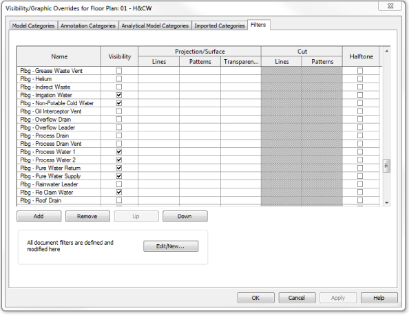
Figure 11.24 Adjusting visibility of pipe and duct systems through filters
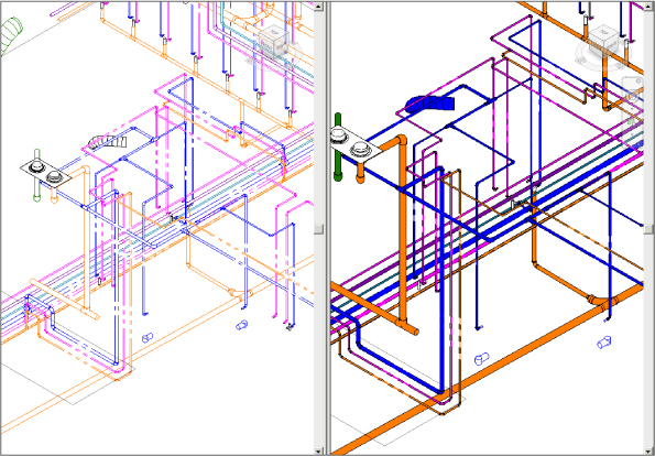
Figure 11.25 The same model displayed without filter overrides (left) and with overrides (right)
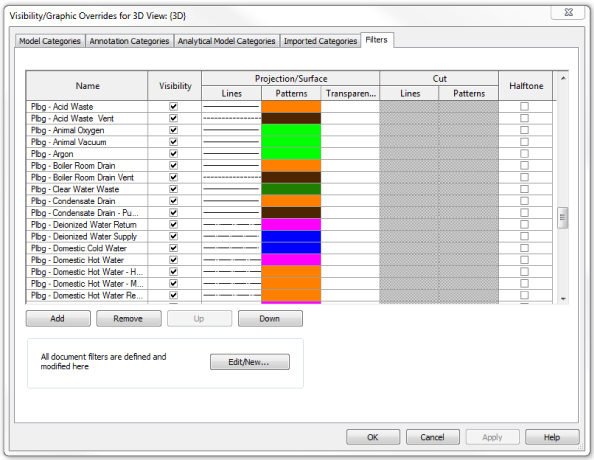
Figure 11.26 Applying filter overrides for 3D views
Now that your plans are coordinated and are displayed the way you require, you are well on your way to completing your documentation.
The Bottom Line
- Adjust the mechanical pipe settings Making sure the mechanical piping settings are properly set up is crucial to the beginning of any project.
- Master It A designer has just been asked to model a mechanical piping layout, and the engineer wants to make sure the designer will be able to account for the piping material used in the layout. What steps must the designer take to complete this request?
- Select the best pipe routing options for your project When using Revit MEP 2015 for your mechanical layouts, you must understand the functions of automatic pipe routing and manual pipe routing. After mastering these functions, you can lay out any type of piping system.
- Master It The engineer has just come back from a meeting with the owner and architect, and it has been decided that there will be a heated-water system and a chilled-water system rather than a two-pipe hydronic system. How would you modify your hydronic layout to accommodate the change?
- Adjust pipe fittings Pipe fittings are needed in systems to make the systems function properly and to produce documentation for construction. Being able to add or modify fittings can increase productivity.
- Master It You have printed a check set for review and have noticed that there are no shutoff valves. Now you need to load the shutoff family. In what directory should you look for pipe fittings?
- Adjust the visibility of pipes Being able to adjust the visibility of pipes gives the mechanical designer or user the ability to set up multiple views and control the graphics for documentation.
- Master It The engineer has just come back from a meeting with the owner and architect, and it has been decided that there will be a heated-water system and a chilled-water system. You have just modified your hydronic layout to accommodate the change. Now the owner wants the pipes to be color-coded so it's easier to visualize the changes. Describe how this would be done.