Chapter 15
Plumbing (Domestic, Sanitary, and Other)
The process we used to route plumbing piping has come a long way from drawing circles and lines on paper. Over the past 30 years, tools such as the straight edge, 30/60 triangles, and the Timely template have been replaced by CAD systems. With more owners requiring BIM, a plumbing designer has to become a virtual pipe installer. Instead of just drawing circles and lines, you have to understand more about how fittings go together to construct your piping design. This is where the Autodesk® Revit® MEP 2015 software excels; it can help you create your designs more accurately and efficiently. But make no mistake—now more than ever before, you need to plan in advance for your plumbing projects. What are the BIM goals for the project? What is the level of detail you are targeting? Develop and document new workflows between you and the architect; create custom content; be much more dependent on accuracy and any changes made by the architect. Those are just a few of the challenges you face, and if you take the time to open the conversation with the architect and internally in your company, you will have accomplished the biggest challenge that people ignore when starting their first plumbing project—planning and setting the expectations!
In this chapter, you will learn to do the following:
- Configure plumbing views
- Customize out-of-the-box Revit plumbing fixtures for scheduling purposes
- Adjust the plumbing pipe settings
- Select the best pipe routing options for your project
- Adjust pipe fittings
Configuring the Plumbing Views
One of the most important parts of a successful plumbing project is configuring the view settings. Many companies tried the plumbing portion of Revit in their early stage of the Revit implementation, and most of them walked away from it saying, “It's not ready yet.” Without the proper configuration, it will never be ready for your company either.
Global Settings and View-specific Settings
You need to adjust several settings so your pipes are properly displayed. The following list is certainly not comprehensive, but it should point you in the right direction and show what to pay attention to when setting up your plumbing sheets:
- All plotted views should be set to Hidden Line.
- Detail Level should be set to Coarse, because most regulatory authorities still require single-line plumbing drawings.
- View range should be adjusted to display necessary pipe systems.
- Visibility Graphics categories should be set to display the appropriate object categories. If worksharing is enabled, it is more efficient to turn off other disciplines' objects by using worksets instead of managing every single object. However, good worksharing practices must be in place, and all objects must be associated with the appropriate workset.
- Pipes going under plumbing fixtures will be completely hidden. To resolve this, plumbing fixtures should be set to Transparent for your model and any linked Revit models containing plumbing fixtures. Note, however, that plumbing fixtures with a high level of detail may start displaying unnecessary lines.
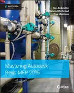
- Wall cut patterns should be turned off. For example, architects often assign cut patterns for their walls to display the fire rating. While this is not important for the mechanical or electrical plans, it is crucial for the plumbing plans, where most objects are in the wall (see Figure 15.1).
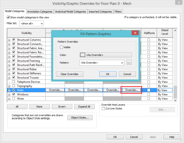
Figure 15.1 Turning off wall cut patterns
- Pipe Rise/Drop Annotation Size under Mechanical Settings should be changed to suit. If you're not sure what you will need, 7/128″ (1. 5 mm) is a good starting point.
- For buildings that are not orthogonally oriented, scope boxes should be set up and associated with the views. Another, simpler method is to rotate the crop region so you can lay out your pipes orthogonally to your screen.
- Configure the Single Line gap under Mechanical Settings to match your company standard. If you do not have one, 3/128″ (0.6 mm) is a good starting point.
Defining Systems Visibility Through Filters
Revit MEP 2015 automatically creates the piping systems for you when you lay out pipes, even when pipes are not connected to plumbing fixtures. When drawing pipes, you need to specify the system type they belong to. The system type can be used to define the line weight, linetype, color, and system abbreviation. The system abbreviation can be used to define what system will appear on what sheet via filters. This helps you hide the mechanical pipes in the plumbing views, as well as separate your sheets between domestic and sanitary pipe layouts.
Establishing a good naming convention for the filters is important, because that defines the order in which you see them in your Properties palette when drawing pipes. The default examples of filters and their settings are not going to get you too far with your projects. We recommend that you take your time and come up with a complete list of systems that your company uses and create them as system types and filters in Revit MEP. Organizing all of them in Excel can be beneficial. Notice that the Filter By setting is set to Equals under the System Abbreviation, as shown in Figure 15.2.
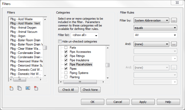
Figure 15.2 Sample filters and their settings
Once the filters have been created, go into a view where you want the different disciplines to show up and type VG to bring up the Visibility/Graphic Overrides dialog box. Click the Filters tab, and add the newly created filters. Using the Visibility check boxes, you can define the systems that would be visible in that view. You can then use this view to create a view template that can be applied to all views that require these settings. Filters can also be used to define color, line patterns, and in some cases, line weights. There are times when you will need filters to do this; however, the recommended place to control these is in the system type. This way, those settings will be global rather than per view. However, the filters will still be managed and they will control what system is visible in what view (see Figure 15.3).
Figure 15.3 Adjusting the visibility of pipe and duct systems through filters
Now that your plans are coordinated and displayed the way you require, you are well on your way to completing your documentation. Consider using the same filters to display 3D views that can enhance the design, making it easier to understand and further reducing errors.
Every rule has its exception, and here is a great example for it. Controlling the colors and line patterns of your systems in the 3D views would color the contour of the pipes, making the pipes hard to see. Instead of going that route, we suggest you override those in the filters with a solid pattern; this way, your 3D views will be a lot easier to see and understand (see Figure 15.4).
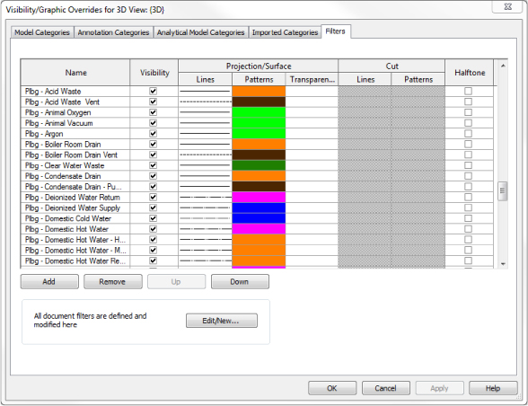
Figure 15.4 Applying filter overrides for 3D views
One common drafting standard is to show all piping serving a given floor in the same view. For instance, on the sheet showing the restroom located on the second floor of a three-story building, you would expect to see all the sanitary piping below the second floor and the vent piping in the second-floor attic serving that restroom. You would not want to see the sanitary pipe serving the third-floor restroom, even though it also occupies the second-floor attic, and you would not want to see the vent piping serving the first floor.
One way to accomplish this selective visibility in projects with overlapping view ranges is with workset visibility. You can assign all the piping serving the first, second, and third floors to specific first-, second-, and third-floor worksets. This will allow you to turn off the first- and third-floor worksets, cleaning up your second-floor view. See Chapter 3, “Worksets and Worksharing,” for more information.
Working with Plumbing Fixtures
Plumbing fixtures are as important to the look of an architectural design as granite countertops or marble tile. Plumbing fixtures, when properly selected, not only enhance the visual design but also promote cleanliness and hygiene. Plumbing fixtures normally are placed by the architect during schematic design to coordinate usability and meet the requirements of governing codes. For this reason it is essential to have good communication between architects and engineers. The power that Revit gives you in collaboration does not reduce the need for a good working relationship with other consultants but rather increases it.
From a plumbing design point of view, different criteria must be examined. What are the water conservation guidelines? Are the plumbing fixtures required to meet LEED standards? Other questions should be asked during design: Will you, as the designer, want to use the same plumbing fixtures that the architect's model uses to connect to your piping, or will you substitute your company's standard fixtures? If so, do you need to apply shared parameters that reflect the design standards required? For example, in the United States there are two major plumbing codes: the Uniform Plumbing Code and the International Plumbing Code. To complicate matters further, some states adopt one of these two codes and then add their own amendments, creating their own state code.
With Revit MEP 2015, you can apply this information through the use of parameters. This can be done in a couple of ways. First, you can edit the information in the family itself by selecting a plumbing fixture family and editing the information through the Type Properties dialog box, shown in Figure 15.5.
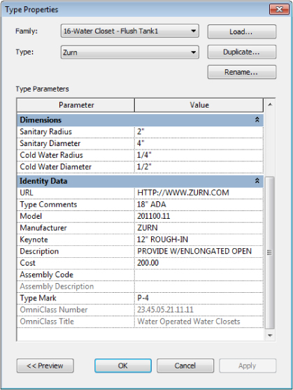
Figure 15.5 Editing the Type Properties
The second way to edit the information is to create a type catalog. Using type catalogs enables the user to easily produce more information about different types or models of the same family. For example, most bathroom manufacturers use model numbers to show the differences in finishes, rough-in locations, handle locations, and handicap accessibility information. Also, type catalogs allow the plumbing design to be easily changed from one manufacturer to another.
The easiest way to create a type catalog is to first open a family and then choose Application Menu ![]() Export
Export ![]() Family Types. This creates a TXT file with all the parameters that are already in that family. The advantage of this method is that it quickly formats the type catalog the way it should be; the disadvantage is that it exports all parameters within the family, and you may need to clean up the type catalog if you don't want all parameters included.
Family Types. This creates a TXT file with all the parameters that are already in that family. The advantage of this method is that it quickly formats the type catalog the way it should be; the disadvantage is that it exports all parameters within the family, and you may need to clean up the type catalog if you don't want all parameters included.
Another method is to create a TXT file manually that will populate the information. To create this TXT file, do the following:
- Open Microsoft Excel. (If you do not have Excel, you can use Notepad or Apache OpenOffice to achieve the same goal. OpenOffice can be downloaded from www.OpenOffice.org.) Save the spreadsheet as a comma-separated values (CSV) file, making sure to name it by using the plumbing fixture's family name.
- Leave cell A1 blank. This is necessary for the type name of the family, such as Kohler or American Standard, to be listed in column A properly.
- Next, you will add the parameter name followed by the parameter unit in row 1. For this example, you will be using the following system parameters from the identity data located in the plumbing fixture family:
Keynote Keynote##other## Model Model##other## Manufacturer Manufacturer##other## Type Comments Type Comments##other## URL URL##other## Description Description##other## - Add the information for each row that you want to be able to schedule (see Figure 15.6).
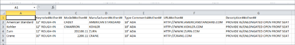
Figure 15.6 Creating a CSV file for type catalogs
- Once everything has been input, save the file. Make sure that when the file is created, it is located in the same directory as the family it references.
- Go to the directory where you saved your file, and rename the extension from
.csvto.txt. To review what the TXT file looks like or to make quick edits without converting back to a CSV file, you can open this file with Notepad (see Figure 15.7).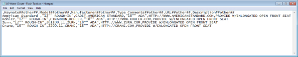
Figure 15.7 Opening the TXT file in Notepad
If you created your file properly, you should see a catalog of information when inserting the family (see Figure 15.8). For more information on type catalogs and their uses, see Chapter 6, “Parameters” and Chapter 19, “Creating Equipment.”
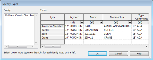
Figure 15.8 Type catalog
Now that you have information added to your plumbing fixture family and you have placed the plumbing fixtures into the plan, you will want to schedule that information.
To accomplish this, go to the Analyze or View tab on the ribbon, and then select Schedule/Quantities. This opens the Schedule dialog box, shown in Figure 15.9. Select Plumbing Fixtures from the Category group, and then click OK.
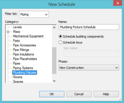
Figure 15.9 Select Plumbing Fixtures from the Category group.
Next, select the information from the Available Fields dialog box and add it to the Schedule Fields (In Order) dialog box. Then click OK, which will create your schedule (see Figure 15.10).
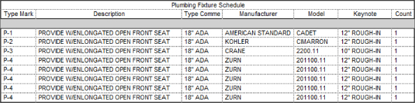
Figure 15.10 Plumbing fixture schedule
Now that you have created the Plumbing Fixture Schedule, you may not want to see duplicate information or blank lines, so you will need to sort the data. To do this, go to the Properties palette, select Sorting/Grouping, change the Sort By option to Type Mark, and then deselect the Itemize Every Instance check box. Now your schedule will show only the items that have unique information (see Figure 15.11). For more information on customizing the appearance and content of schedules, see Chapter 7, “Schedules.”
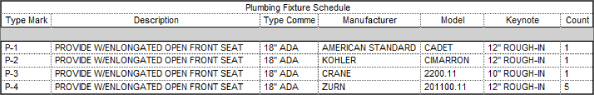
Figure 15.11 Sorted schedule
Working with Architectural Linked-in Plumbing Models
When using Revit MEP for plumbing, you have two main options for coordinating plumbing fixtures between architectural linked-in models and plumbing models. The first option is to manually place the plumbing designer's edited plumbing fixtures over the architectural plumbing fixtures. The second option is to use the Copy/Monitor feature.
Using the Copy/Monitor feature either places an exact copy of the architect's fixture family or allows you to select your family. You can use a family that has already been edited with proper connectors and scheduling information. When you are placing fully modeled plumbing fixtures with connectors, you will need to turn off the architectural plumbing fixtures. Otherwise, any slight difference in graphical representation or location between your plumbing fixtures and the architectural plumbing fixtures will be a disaster for your final plot sheets. Using plumbing fixture assemblies or connector placeholders is more forgiving. In this case, the architect is in control of the graphical representation of the plumbing fixtures, and you are in control of the plumbing fixture information and specifications. By fixture assemblies or connector placeholders, we mean placing your own families, which could be as simple as cylinders that are hosting the necessary connectors and all parameters for scheduling purposes. When you place those, you can decide where to put them and how to orient them, whereas with the Copy/Monitor tool as mentioned earlier, you are dependent on the architect's family building skills.
With either method, you have to take care that your fixtures remain coordinated with any architectural plan changes. If you place your families manually, you have to check locations visually. If you use the Copy/Monitor function, Revit will notify you that there has been a change via the Collaborate ribbon tab ![]() Coordination Review. Also, the Copy/Monitor feature does not automatically update to show any new fixtures that the architect may have added.
Coordination Review. Also, the Copy/Monitor feature does not automatically update to show any new fixtures that the architect may have added.
You should also consider how the architectural families and your families are made. The two major points of consideration are the orientation and the insertion point of the architectural families and your families. If they don't match, Copy/Monitor most likely will create more work for you because you will have to move and rotate every instance of a family that doesn't match orientation and position. But by doing that, you would also produce a Copy/Monitor alert. So, the bottom line is that if the orientation and insertion point don't match, it is easier to place the families manually, and if you like the benefits of Copy/Monitor alerting you when the architect moves those elements, you can still monitor your manually placed fixtures against the architectural fixtures. We'll talk more about this later in the chapter.
Instead of duplicating the fixtures in the architectural and plumbing files, another scenario you could consider is to have the engineering company take them over and let the architect display the plumbing fixtures from the plumbing model. This will certainly eliminate inconsistency between the two models, but it could be hard to achieve for some companies based on their culture and workflows.
With either of the options, you can use plumbing fixture families that represent only the piping portion of each fixture. These custom pipe assemblies are fittings preassembled or modeled to line up in the locations of the linked architectural plumbing fixtures. These are created as plumbing fixture families.
Creating Custom Pipe Assemblies
Many piping conditions are not worth modeling piece by piece, such as piping beneath counters for p-traps and supply lines or complicated pipe and valve assemblies. If a plumber can preassemble these off site or perhaps prefabricate them as an assembly on site and then just move them into place; it may be logical to emulate this by building custom families that represent a complete assembly instead of using individual families that must be connected to one another repeatedly in the model.
Custom pipe assemblies can be represented in one of two ways in the Family Editor. First, you can use sweeps to represent the p-trap, wye, and associated piping, as shown in Figure 15.12. This method creates a smaller file size and reduces the size of the overall plumbing model. Assemblies representing fittings with sweeps and extrusions would not allow you to schedule the fittings directly. However, if quantity takeoffs are important to you, they can be achieved by creating shared parameters that store the number and type of fittings that are used in the assembly.
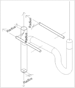
Figure 15.12 Representation of a pipe assembly created with sweeps
The second method is to assemble nested families, which can allow for better quantity takeoffs for all the fittings, create more-accurate dimensional information when supplied by manufacturers, and be easier for the plumbing designer to create. The downside is that it produces a larger family file. This second option will help you achieve more of the building information modeling (BIM) status as well as a more accurate visual representation of the plumbing systems in addition to taking advantage of already existing content, hopefully reducing modeling efforts (see Figure 15.13).
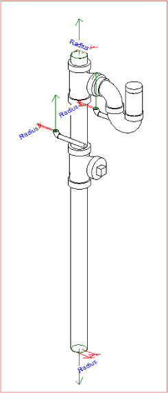
Figure 15.13 Nested pipe assembly
Now let's examine how nested piping assemblies are put together and some key areas to be mindful of:
- Open the
PR-Sinks and Lavs.rfafile found at www.sybex.com/go/masteringrevitmep2015. - Several modified pipe-fitting families are nested into this family that make up the assembly. They are
Trap P - PVC-DWV.rfa,Tee Sanitary-PVC-DWV.rfa,PVC-DWV Pipe Section.rfa,Plug-PVC-DWV.rfa,Elbow -Copper Type L.rfa, andCopper Type L Pipe Section.rfa. These can all be found at www.sybex.com/go/masteringrevitmep2015, or you can get the originals from thePipe Fittingdirectory located in the Imperial library. - When placing the fittings together, make sure to align, lock, and dimension each one, as shown in Figure 15.14. If not, the fittings will pull apart.
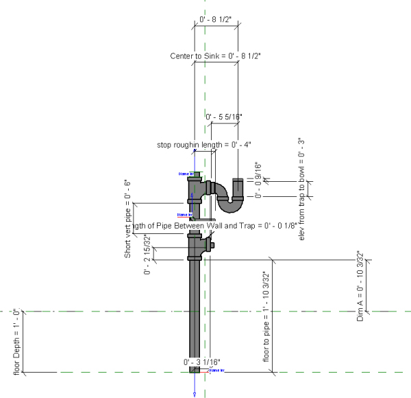
Figure 15.14 Aligning, locking, and dimensioning nested families
- When creating your pipe assembly, make sure that the Center Front/Back reference plane is placed at the wall's finish face in the project. When you do this, the family will easily snap into place.
- You can add parameters to flex your piping to align it under a sink or lavatory or to give a certain depth to account for a floor slab. You can make these parameters as complex or as simple as you want (see Figure 15.15).
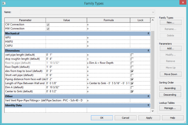
Figure 15.15 Using parameters to flex the piping assembly
- Make sure that when adding a water piping connection to a rough-in pipe, you add an elbow pointing in the direction of the pipe routing (for example, from the floor or from the ceiling). This will help with autorouting and manual routing (see Figure 15.16).
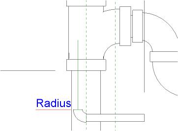
Figure 15.16 Adding a simple elbow pointed in the direction of flow
Now that you have reviewed some of the items that make up a pipe assembly, you can place the pipe assembly family in your plumbing model and align it with the architectural plumbing fixtures without having to turn them off. If the architect adds a plumbing fixture, you now have the capability to view it. By following this workflow, you can both tag and schedule the pipe assembly family while the graphic representation needs are satisfied by the family in the architectural linked file.
Copying/Monitoring Plumbing Fixtures
Now let's take it a step further. If the plumbing fixtures that the architects are using match the same orientation and insertion point of your pipe assemblies, you can copy/monitor the pipe assemblies directly behind the plumbing fixtures. Then, when the architect moves a plumbing fixture, you will receive a warning that you need to coordinate your view (see Figure 15.17).
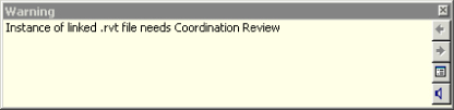
Figure 15.17 Coordination Review warning
You will also have the capability to copy and change all of the plumbing fixtures on multiple levels at one time. This can be a huge time-saver.
To use Copy/Monitor, do the following:
- Choose Collaborate
 Copy/Monitor Select Link, and then select the architectural background.
When you click the architectural file, the ribbon should change to Copy/Monitor. If it doesn't, that means you didn't click the architectural file. Trying to select objects by clicking on their surface is a common mistake. In Revit, all selection is done by clicking the contour of the object, not on the surface. If that happens to you, you will need to start over with the Copy/Monitor command.
- In the Copy/Monitor panel, select Batch Copy. Click Specify Type Mapping Behavior & Copy Fixtures.
- A Coordination panel opens, displaying Category and Behavior selection tables. Select Type Mapping, and replace the plumbing fixtures from the architect with the ones you created (see Figure 15.18).
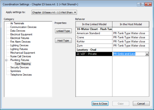
Figure 15.18 Type Mapping option
- Click Copy and then select the plumbing fixtures you want to copy (see Figure 15.19).
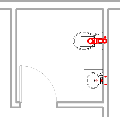
Figure 15.19 Copying and replacing fixture types
- If you are working on multiple floors, you can select the plumbing fixtures from all levels while in an elevation view, and then you can use the Filter command to isolate only the plumbing fixtures.
If you highlight the assembly, you should see the monitoring symbol on the assembly, as shown in Figure 15.20.
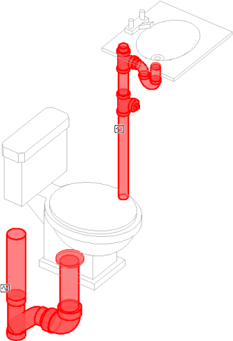
Figure 15.20 Monitoring symbol shown on the assembly
To take full advantage of the Copy/Monitor feature, you will need to coordinate all of your plumbing fixtures with your pipe assemblies, but you will find it is time well spent.
A less traditional way of using the Copy/Monitor tool, especially when the insertion point and orientation between the architectural fixtures and yours don't match, is to batch-copy all of the architectural plumbing fixtures and place a little dot or a cylinder. The idea is to create a relationship between your model and the architectural model that will provide you with alerts whenever the architect moves or deletes plumbing fixtures. Remember, you will not be notified when the architect places new fixtures, but the workaround for that is to batch-copy/monitor all fixtures with every update of the architectural background. This way, you will be able to see the number of newly copied/monitored elements (that is, new plumbing fixtures) in the architectural model. You will still need to manually place your own plumbing fixtures or pipe assemblies, but knowing what changes the architect made to the plumbing fixtures will be a huge time-saver.
Choosing Pipe Settings and Pipe Routing Options
When setting up piping to route, you should apply the proper pipe material so that quantity takeoffs can be easily scheduled. Another reason to apply the appropriate pipe material and pipe fittings is to get the invert elevation for sloping systems. If the pipe material and fittings are incorrect, the invert elevation value will not be reliable.
There are several areas you have to adjust to set this up properly. Most important are the Piping Systems and Pipe Types settings. These and other piping parameters are discussed at length in Chapter 11, “Mechanical Piping.” Also covered in that chapter are the two routing options, autoroute and manual. Here, you will examine the options available for sloped piping. One thing to note is that currently Revit doesn't come with no-hub fittings. Some manufacturers are making them, but be aware that they can be over-detailed and you may experience performance issues with your projects. As a start, using the PVC fittings that come with Revit MEP 2015 should produce reasonable graphical results.
Sloping Pipe
When modeling pipe, you can use either the autoroute or the manual routing feature. You are more likely to have success with a manual layout when using sloped pipe. Before you lay out your pipes, it is a good idea to check the Slopes settings located under Manage ![]() MEP Settings
MEP Settings ![]() Mechanical Settings
Mechanical Settings ![]() Pipe Settings
Pipe Settings ![]() Slopes. From here you will be able to add or delete slopes that would be available for you to use when drawing pipes.
Slopes. From here you will be able to add or delete slopes that would be available for you to use when drawing pipes.
For sloping pipe to work properly, it needs to have start and end points. To set up sloping pipe, open Ch15_plumbing.rvt and Ch15_base.rvt. This file is found at www.sybex.com/go/masteringrevitmep2015. Next, do the following:
- Open the Sanitary view and make sure that you have your view range set correctly because you are going to be routing pipes below 0′-0″ (0 mm). Select View Range from the Properties palette, and change Bottom and View Depth to Unlimited for your lowest-floor views, as shown in Figure 15.21. A good starting point for upper-floor view ranges is –3′-0″ (–1 m). (This setting will vary according to your project.)
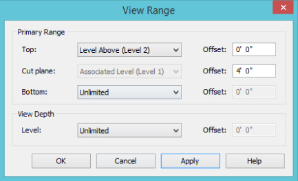
Figure 15.21 View Range settings
- Look at your routing choices for your main. Then locate your end run fixture, floor clean-out, or wall clean-out.
- Locate your sanitary point of connection (POC) outside the building. Locate the sanitary piping at –4′-0″ (–1.2 m), below the finished floor.
- Select the Pipe toolbar located on the Systems tab of the ribbon. Before you start routing your pipe, be sure to select Slope Up, as shown in Figure 15.22, and set the Slope Value to 1/8″ / 12″ [25 degrees]. Make sure you have the justification set to your preference. You can also enable the Show Slope tooltip, which would display Start Offset, Current Offset, and Slope right next to your cursor as you draw your pipes.
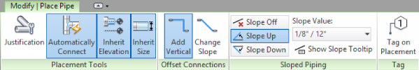
Figure 15.22 Recommended settings for drawing nonsloping pipe layouts
- Start your run from the sanitary point of connection, and route into your last fixture or clean-out. You now have a main trunk off of which you can build your system.
- Select the Pipe toolbar, and then select the point on the main from which you want to route. After starting your pipe run, you can select the Inherit Elevation and Inherit Size buttons from the toolbar, as shown in Figure 15.23, or you can press the spacebar one time. This makes the new piping connect at the same elevation and size as the pipe main you selected to start the run. Then route out to the water closets or any other components that take a 1/8″ [25 degree] slope.
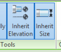
Figure 15.23 The Inherit Elevation and Inherit Size options
- Route all of your sloped pipe that contains the same degree of slope first. Then route all of the next matching slope. Having a redundant pattern will add to your efficiency and productivity. Now you should have a sloped system (see Figure 15.24).
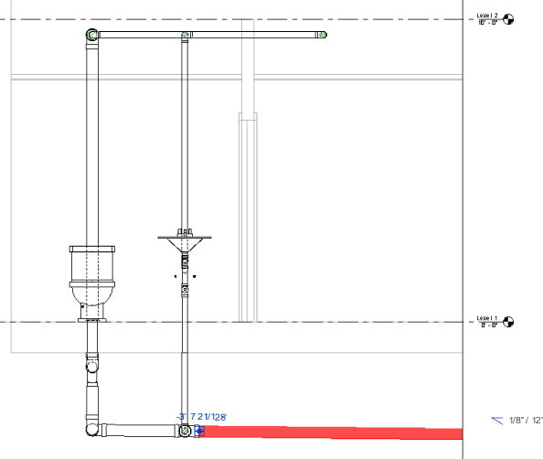
Figure 15.24 Sanitary layout with sloped piping
- New to Revit MEP 2015 is the ability to choose whether you want to use Add Vertical or Change Slope when connecting from A to B (see Figure 15.25). This replaces the Ignore Slope To Connect option found in previous versions of Revit.
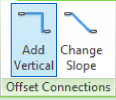
Figure 15.25 Add Vertical and Change Slope options
Annotating Invert Elevation and Slope
Once your piping model is at the desired slope and elevation, you can easily apply parametric elevation and slope annotations. Choose Annotate ![]() Dimension
Dimension ![]() Spot Slope or Spot Elevation. The slope tag is very simple; it can be placed at any point along a pipe run while you're viewing single- or double-line pipe.
Spot Slope or Spot Elevation. The slope tag is very simple; it can be placed at any point along a pipe run while you're viewing single- or double-line pipe.
The elevation tag is more complicated. The Spot Elevation tag can show only the top and/or bottom elevation of the pipe selected. You must be able to see double-line pipe (Fine Detail) in order to place the Spot Elevation tag. This tag exists only within the project. It is a system family, and it cannot be edited in the Family Editor. This means that all changes are done in the Properties and Type Properties palettes within the project interface. In the Options Bar, you will want to make sure to set the elevation to reference the correct level. Also in the Options Bar, you should set the Display Elevations option to either Bottom Elevation or Top And Bottom Elevation. In the Type Properties dialog box, you will likely want to change the Units Format value and the Display Elevations format to match your standard for labeling pipe elevation—for example, B.O.P. = bottom of pipe (see Figure 15.26).
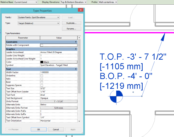
Figure 15.26 Customizing the Spot Elevation tag
If you prefer to annotate the elevation of the pipe centerline, you will have to use a pipe tag. This is the same type of annotation family as the common pipe diameter tag. You can duplicate and edit that family to change the label to include the parameters Start Offset and End Offset. Note that these parameters can display the elevations of only the two endpoints of each pipe segment. Like the Spot Elevation tag, they cannot display the elevation at any point along the pipe segment.
Using Fittings
Without fittings, piping would not be worth a whole lot. Fittings help shut off, regulate, and open up flow of fluid in systems—and, most important, save lives. In Revit, most fitting families have the following functions:
- End Cap These can be placed only at the end of pipe.
- Tee, Tap, Wye, and Cross These can be placed anywhere along pipe runs.
- Transitions, Couplings, and Unions These can be placed only at the end of pipe. They are used to join a smaller, larger, or same-size pipe.
- Flange These can be placed at the end of pipe or face to face with another flange.
Using Pipe Fitting Controls
Understanding pipe fitting controls can really make life easier if you are routing a lot of piping. When you are laying out your piping, turn 90 degrees to create an elbow. If you click the elbow, you will notice a plus (+) sign. If you click that sign, it will change from an elbow to a tee, allowing you to add more piping and to continue your pipe routing. If you select the minus (–) sign, it will downgrade the fitting. When you see the ![]() symbol on a fitting, it allows you to rotate the fitting, and the
symbol on a fitting, it allows you to rotate the fitting, and the ![]() symbol allows you to flip the fitting.
symbol allows you to flip the fitting.
Placing Valves
When you need to add valves to your piping, select the Home tab and click Pipe Accessories. Use the Type Selector to select the type and size of valve you want to use. Most valves will break into the piping and connect as you simply select a piece of pipe (see Figure 15.27).
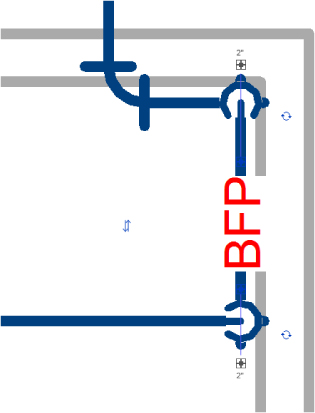
Figure 15.27 A fitting breaks into the piping system.
The Bottom Line
- Configure plumbing views Learning the proper way to set up your template will ensure a consistent graphical representation across projects and improve efficiency.
- Master It When you are setting up your project/template views, where would you control the linetypes and colors of pipe systems?
- Customize out-of-the-box Revit plumbing fixtures for scheduling purposes Out-of-the-box plumbing fixtures (or any other equipment for that matter) do not have all the necessary parameters to complete a typical plumbing schedule.
- Master It What would you need to do in order to create a plumbing fixture schedule?
- Adjust the plumbing pipe settings Pipe settings are crucial to the ability to have Revit MEP model your plumbing layout, the way it will look, and the way it will perform.
- Master It Do fitting parameters have to be set up in the system pipe types?
- Select the best pipe routing options for your project When using Revit MEP 2015 for your plumbing layouts, you must understand the functions of automatic pipe routing, manual pipe routing, and sloping pipe. Once you master these functions, you can lay out any type of piping system.
- Master It A plumbing designer has just been asked to lay out a sloped plumbing system and has only a day to pipe up a clubhouse. Where should the designer start the pipe route?
- Adjust pipe fittings Pipe fittings are needed in systems to make the systems function properly and to produce documentation for construction. Being able to add or modify fittings can increase productivity.
- Master It You have just finished your modeled layout and have given it to your employer for review. Your boss asks you to remove a couple of elbows and replace them with tees for future expansion. What would be your method to accomplish this quickly?