Chapter 19
Creating Equipment
The equipment families used for the design of your MEP engineering systems are important—not only for coordinating the physical model but also for establishing the components that serve as the equipment for your engineering systems. The properties you assign to your equipment families will define how they can be used in relation to other components within a system.
Many mechanical and electrical equipment items require clearance space for maintenance and installation. With the Autodesk® Revit® MEP 2015 software, you can define the required clearances for equipment families either directly in the family files or as a separate component. This gives you the ability to coordinate your model fully to avoid costly conflicts during construction.
Creating equipment families that are generic enough for use early in the design process, yet parametrically changeable, will help you transition through design phases and changes to systems smoothly and efficiently. The physical properties of MEP equipment are similar enough in most cases to use simple geometry that can be sized according to specified equipment.
Whether you are creating equipment for mechanical, plumbing, or electrical systems, knowing how the equipment will be used from an engineering standpoint as well as a modeling standpoint will help you create the types of families that fit your workflow and processes best.
In this chapter, you will learn to do the following:
- Create MEP equipment families
- Add connectors to equipment for systems
- Create clearance spaces for equipment
- Add parameters to equipment
Modeling MEP Equipment
With the rising popularity of building information modeling (BIM), more and more manufacturers are providing their products for use in a virtual model environment. This can be very useful when you get to the stage in your design where you can specify the exact equipment to be used. Early in the design, however, you may not know what equipment will be used. Furthermore, you may not yet have done calculations that would determine the size of the equipment needed.
All of this boils down to a need for MEP equipment families that are realistic in size and function but also parametrically editable to compensate for changes in the design of both the project and the systems used. These families need to be flexible enough to handle the seemingly constant change that occurs early in the design process, but they also need to have the functionality to represent their intended purpose accurately.
Some of the resistance to adopting a BIM approach for designing a project stems from the fact that too much information is required early on that is not known in a typical project environment. Having usable equipment families can alleviate some of that concern and allow you to move forward with your design processes.
Hosting Options
When planning for a family, there are plenty of things to consider. One of the first is how the family will be placed into a project model. Is the equipment inline with duct or pipe? Does the equipment require a building element to which it will be attached? Knowing the answers to these types of questions will help you start with the right family template so that the equipment you create can be used properly in your projects.
Generally speaking, there are three hosting family behaviors: generic, face based, and object based. The generic families are the most common families, and they are not constrained to any adjacent geometry; instead, they are constrained to the level they are placed on. Face-based families are commonly used as grills, diffusers, plumbing fixtures, and so on. In order to place those families, you need to have a present host (wall, floor, counter, and so on). The host can be either in your MEP model or in any Revit-linked files. Object-based families are almost never used in Revit MEP. This is because they require the physical presence of the host in your model and they can't be placed on hosts that exist in any of the linked Revit models. In other words, you can't place any object-based diffusers on the architectural ceiling unless you have ceiling objects modeled in your own MEP model (not through the link).
To make the right decision about what hosting behavior you should choose, you need to know the pros and cons of those behaviors.
Generic (nonhosted) families behave pretty much like any other object in Revit—they change location only if you move them.
Object-based families behave like face-based families for the most part, except that they need the host to exist in the model and not be part of a linked Revit file.
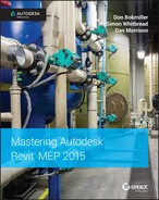
Face-hosted families have one major advantage: they follow the plane of the host. Anytime the architect adjusts the ceiling location, your diffusers will adjust accordingly. Cool, right? Ceiling diffusers follow the elevation of the ceiling, and the water closet follows the plane of the wall (not the elevation, but the actual plane of the wall finish). Ironically, this advantage is its biggest disadvantage. It is important to understand that as your objects move with the hosted element, any connected pipes or ducts will adjust to fit and can potentially disconnect and break the integrity of the system. When you receive the new architectural background and try to open your MEP model, you will get the message shown in Figure 19.1.
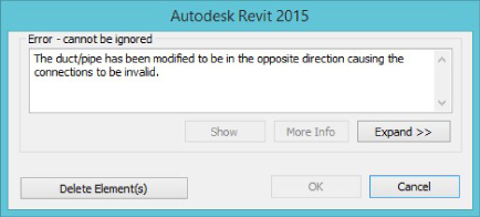
Figure 19.1 Message that appears when you're using face-hosted families
This message, as you can see, has only two options: Delete Element(s) will delete some pipes, pipe fittings, ducts, and duct fittings; Cancel will cancel the process of opening your project. The bottom line is that in order to open your project, you must delete certain elements. It is good practice when you are designing with Revit MEP to have all pipes and ducts connected, and as you move a main piece of pipe, any branches that exist should extend or shorten. Knowing that fundamental behavior of Revit, let's translate it to a face-hosted family that is following the host. Let's say you have placed a plumbing fixture on top of the architectural plumbing fixture; the only difference is that your plumbing fixture has a connection point where you can connect your pipes, as shown in Figure 19.2.
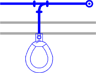
Figure 19.2 Connected plumbing fixture
When the architect relocates the hosting wall (toward or away from the main), your plumbing fixture will follow. Revit will do its best to maintain the integrity of any connected pipes. Therefore, the short pipe coming off the main will either extend or shorten. If this pipe is shortened so far that the elements can't remain connected, Revit will not know how to reconfigure the whole system and will simply try to delete the short pipe. This is why you'll get the message that certain elements need to be deleted.
Once you accept the message and open your model, the only way to find which pieces have been deleted is to inspect the entire model visually. This can be a time-consuming and frustrating process.
Face-based families are powerful and at the same time dangerous. As a rule of thumb, you should consider creating face-based families for any objects that require following the host but don't have any connected elements (receptacles, thermostats, switches, and so on). When you have elements connected to the object, proceed with caution because those connections may break.
Equipment that sits on the floor of a room or at the exterior of a building does not need to be created as a hosted family. When you place a generic (nonhosted) family into your project, it will be associated with the level of the view in which it is placed. However, if the equipment requires a pad for housekeeping or structural support, you may want to make the family face hosted so it can be attached to the face of the pad. This will allow for coordination with changes to the pad, assuming that the structural engineer or architect provides the pad. If the equipment you are creating always requires a pad, you can build it directly in the equipment family—that's assuming that you are responsible for placing and sizing the pad. When the structural engineer is responsible for the equipment pad, you can use the Offset parameter of your mechanical equipment to elevate it on top of the pad.
You can also use the Align tool to align your equipment to the architectural wall, floor, or ceiling; however, your equipment will not move with the architectural element if that model is adjusted.
Once you have determined the hosting behavior of an equipment family, you can build the solid geometry of the equipment in relation to the host object or reference plane that represents how the family will be placed into a model.
Family Categories
There are essentially two choices for categorizing your equipment families: Mechanical or Electrical Equipment. This may seem limiting, but keep in mind that you can make any subcategories you choose. It may be necessary to categorize an equipment family as some other model category, depending on how it is used in your projects. This is typically done for visibility control or scheduling purposes, although for scheduling the most common way is to use a parameter for filtering out just the equipment you want to display in your schedule. Variable air volume (VAV) boxes need to be in a different schedule than boilers, although both of them are mechanical equipment. By creating a parameter such as Schedule Filter and assigning the value in the VAV box family to, say, VAV, you will be able to schedule (filter out) VAV boxes separately from the other equipment in the project. Alternatively, if you use a rigid naming structure in your family names or type marks, these can be used to separate out the different equipment elements in schedules.
You can set the category of a family by clicking the Family Category And Parameters button on the Create tab in the Family Editor, as shown in Figure 19.3.
Figure 19.3 Family Category And Parameters button
When you categorize a family as Mechanical Equipment, you can set its behavior with the Part Type parameter, as shown in Figure 19.4. The Normal option is for equipment that is simply placed into the model and stands on its own, while the Breaks Into option is for equipment that is inline with ductwork or pipe. The Breaks Into option allows you to insert the family directly into a run of duct or pipe without having to first create an opening for the equipment.
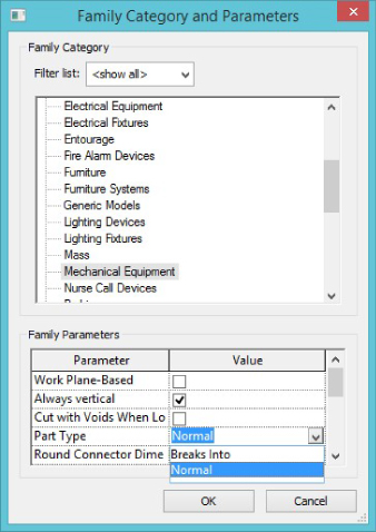
Figure 19.4 Part Type options for Mechanical Equipment families
The Part Type parameter for Electrical Equipment families also has options for defining the equipment behavior, as shown in Figure 19.5. These options let you define how the equipment is used in an electrical system.
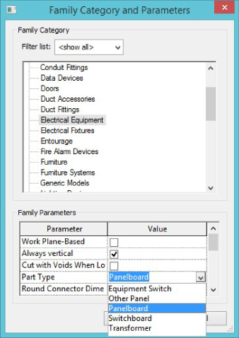
Figure 19.5 Part Type options for Electrical Equipment families
If you choose the Panelboard option, you can set the configuration of the breakers and circuit numbering in the panel. This corresponds to the template used for panel schedules, as shown in Figure 19.6. Panel Configuration, along with Part Type parameters, define the relationships between panels in the project schedules. Therefore, careful consideration is advised.
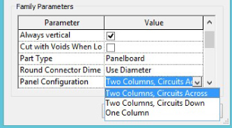
Figure 19.6 Panel configuration for electrical equipment
Since Revit MEP 2014 there has been an option for Round Connector Dimension. It is here that you can select whether you wish to use Radius or Diameter to dimension your round connectors, be they ducts, pipes, or conduits.
Another family parameter that you should consider is the Always Vertical option. Selecting this option causes the equipment family to always appear vertical at 90 degrees, no matter how the host is sloped. This setting is used for nonhosted families. If you are creating a nonhosted family and you want to be able to place the family in any orientation, you can set the Work Plane-Based option. This allows you to place a nonhosted family onto any workplane defined in your project. Otherwise, if you place a nonhosted family into a project and it is associated with the level of the view placed, you will not be able to rotate the family in section or elevation views.
Setting the family to Work Plane-Based does not mean that you can rotate the family in section or elevation, but you can create a reference plane that is at the desired rotation in the project and associate the family with that plane, as shown in the section view in Figure 19.7. When you place a Work Plane-Based family into a project, the option to place the family onto a face is available on the Placement panel of the contextual tab.
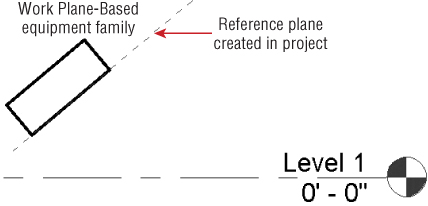
Figure 19.7 Work Plane-Based equipment in a project
This functionality is useful because it allows you to use nonhosted families in a face-hosted fashion.
Detail Level
When you are modeling your equipment families, consider the amount of detail required to represent the equipment. Mechanical components can be complicated structures that include many intricate parts. It is not necessary to model your equipment families to a high level of detail for them to function properly in your projects. If you need to show equipment with a lot of detail, you can use model lines or symbolic lines to represent the equipment in views where the high level of detail is needed while keeping the family geometry simple.
Most equipment families can be modeled using simple geometric forms such as cubes and cylinders. If the equipment family you are creating requires more complex geometry, you will need to use the other modeling tools available in the Family Editor, such as the Sweep, Blend, and Revolve tools.
For instances where you need to show only the amount of space required for equipment, you can model it as a box that is visible in Coarse detail views. More-detailed geometry can be modeled to show in views with a finer level of detail. The important thing to remember when using this technique is that the connection points for ductwork or pipe should be located on the outer edges of the box geometry. Otherwise, you might end up with pipes and ducts that appear disconnected, as shown in Figure 19.8.
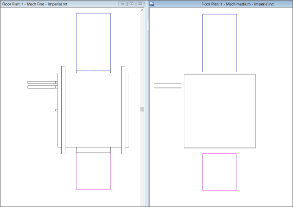
Figure 19.8 Pipes and ducts that appear disconnected when in Medium detail level
Geometry for Connection Points
MEP discipline equipment families can include connectors for ducts, pipes, conduit, and even cable tray if necessary. These connectors are added to define the function of the equipment from an engineering standpoint. Connectors are added by one of two methods: either by placing them on a face of the solid geometry or by associating them with a workplane within the family. When you associate a connector with a workplane, it can be located anywhere in that plane. Connectors placed with the Face option on the Placement panel of the contextual tab will automatically attach to the center of the face.
Using the Face option is useful when you know that the connection point is always at the center of the geometry—because if the geometry changes size, the location of the connector will adjust, or if the geometry changes location within the family, the connector will move with it. This method requires less constraint within the family for the location of the connector, but it may be necessary to model extra geometry to provide a correctly located face for a connector.
Creating geometry for the location of connectors is an easy way to manage not only connector locations but also connector sizes. The size of a connector can be associated with the size of its geometry host face. This allows for accurate modeling of connection points of different family types within a family.
Geometry used for connection points may be more easily dimensioned than connectors themselves because you can dimension to the edges of geometry, whereas connectors can be dimensioned only to their center points. For example, if you have a rectangular duct connection that varies in size yet needs to maintain a certain distance from the edge of the unit, you can model geometry that is constrained to the dimensional requirements and then host the connector to that face. Figure 19.9 shows an example of an extrusion used in this manner. The 0′-6″ (150 mm) and 0′-4″ (100 mm) dimensions are locked to hold the extrusion in place when the Unit Height and Unit Width parameters are changed and when the SupplyHeight and SupplyWidth parameters change.
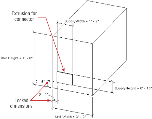
Figure 19.9 Extrusion used for connector host
Using extrusions for connection points can make it easier to identify where to connect pipes, duct, or conduit to your equipment when working with the family in a project. More information on connector geometry is provided in the section “Adding Connectors to Equipment Families,” later in this chapter.
Equipment Pads
When you are creating an equipment family that needs to be mounted on a pad, it may be best to include the pad geometry directly in the equipment family. This enables you to ensure that the appropriate dimensions are used for the pad without having to make any changes in another file, such as a structural or architectural link. If the equipment does not always require a pad, you can use parameters to control the display of the pad. Family types can be created for easy selection of pad-mounted versions of the equipment.
The key to creating pad geometry in an equipment family is to provide a reference for the top of the pad so that the equipment geometry can be modeled in the correct location and maintain a proper relationship with the pad. If you are creating a face-hosted family, the pad should be modeled so that it is associated with the host extrusion, as shown in Figure 19.10. Keep in mind that pads don't always have a parallel top and bottom. If the roof is sloping, obviously the pad needs to follow the slope, but it still needs to create a level top surface for the equipment. In those cases, the pads can be a bit more complicated. A common approach is to create multiple extrusions within the same pad family and control which one is visible and when (through visibility parameters) based on the sloping conditions in the project.
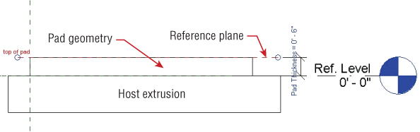
Figure 19.10 Pad modeled in equipment family
Adding Connectors to Equipment Families
The connectors that you add to an equipment family will ultimately determine the types of systems for which that family will be available in your Revit projects. Connectors can be added for the completion of air, fluid, and electrical systems when the family is selected as the system's equipment in your project.
In most cases, the location of connectors on equipment families is easily handled by geometry modeled specifically for the connector. However, it is not always necessary to have connector geometry. Some equipment families are simply used for equipment location and do not need to be modeled to any level of detail. Early in the design of a project, you may want to use placeholder equipment families until specified equipment can be chosen based on calculations. It is still helpful for these types of families to have connectors so that duct, pipe, and conduit can be connected and system analysis can be performed.
If you place the connectors by reference planes, you can dimension directly to a connector by selecting it and then activating the temporary dimension to the center of the connector. Once it is activated, you can associate the dimension to a parameter. This can be done only if you use the Work Plane option for placing the connector. Using the Face option constrains the connector to the center of the face so its location cannot be changed without changing the host face. Figure 19.11 shows how a connector placed on a Work Plane can be dimensioned and parametrically managed.
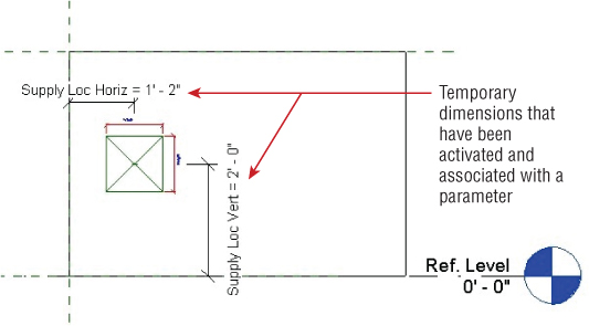
Figure 19.11 Connector location dimensions
In this example, if you want to keep the right and bottom edges of the connector static when the connector changes size, you would need to write a formula for the connector dimension parameter. For example, with a parameter that defines the connector width, such as SupplyWidth, the left edge of the connector can be made to stay at 0′-8″ (200 mm) from the left edge of the equipment by using a formula for the Supply Loc Horiz parameter, as shown in Figure 19.12.
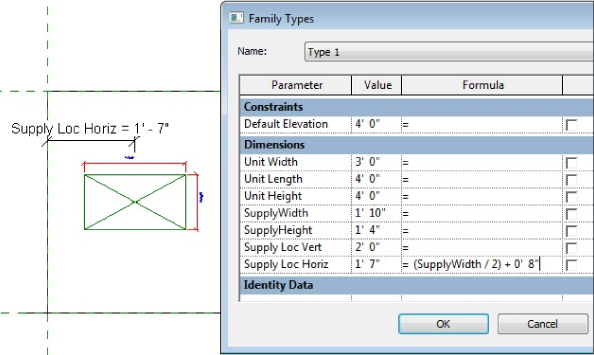
Figure 19.12 Connector location using formula
When you have equipment that has several pipe connectors, it is helpful to create geometry for the connectors. Otherwise, you would have to define a reference plane for each connector unless they all connect at the same plane. With geometry used to indicate a point of connection, you can dimension and constrain the geometry and then use the Face option for connector placement. This does not eliminate the need for dimensions or constraints; it only takes them off the connector object itself.
When you sketch a circle to create a cylinder, the point at which you draw the center can be dimensioned while you are in sketch mode. This dimension can be used for the location of the connector, as shown in Figure 19.13. The radius of the sketch can also be dimensioned and associated with a parameter for easy size adjustment. Remember, when creating circular connectors, use a circle for the sketch, not an arc that is copied/mirrored. This is because the center point of the pipe connector will snap to the centroid of one of the arcs, not that arc's center point.
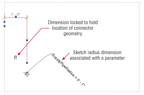
Figure 19.13 Geometry for cylindrical connector
Revit MEP 2013 was the first version to introduce the Diameter dimension. This allows you to control round extrusions and connectors with one parameter, and without the additional formulas that were required in the past.
Reference planes or lines can also be used to determine the location of the connection point geometry. This is easily done for pipe connections by activating the Center Mark Visible parameter of the circle you are sketching, as shown in Figure 19.14.
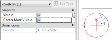
Figure 19.14 Using the parameter Center Mark Visible
While you're in sketch mode, the center mark allows you to align and lock the sketch to reference planes or lines used to control the geometry location, as shown in Figure 19.15.
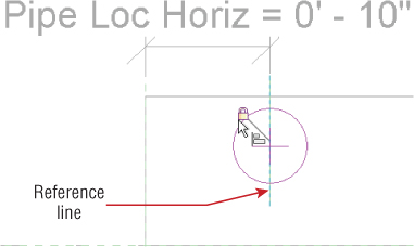
Figure 19.15 Sketch center mark aligned to reference line
With the geometry in place, a connector can be added by using the Face option for placement.
You can adjust the connector properties to associate the size of the connector with the parameter created for the geometry diameter, as shown in Figure 19.16. Associating the values to parameters in this way is known as parameter mapping. Parameter mapping allows you to make connector parameters visible and accessible in project environments.
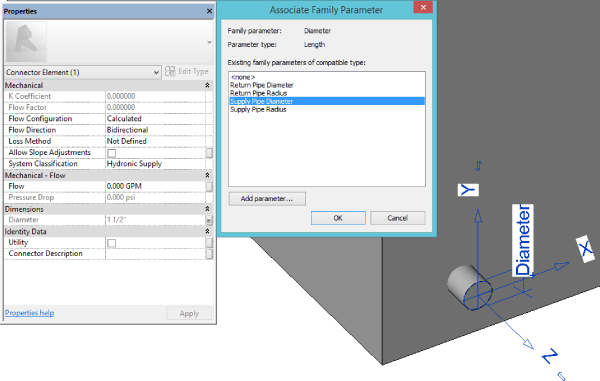
Figure 19.16 Associating a parameter with the connector diameter
The Diameter parameter has been available only since Revit 2014. As mentioned earlier, you can switch between radius and diameter by using the Round Connector Dimension parameter in the Family Category And Parameters section. Alternatively, you could also do this via the Properties palette (see Figure 19.17).
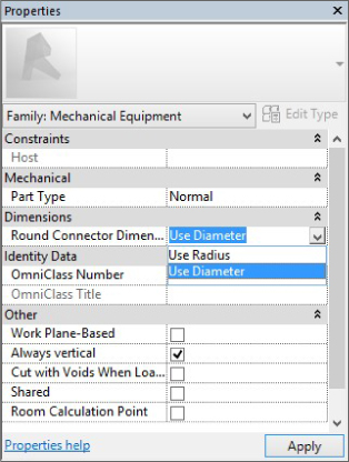
Figure 19.17 Changing between radius and diameter
Using the Face option is the easiest way to place connectors into a family. The direction of the connector can be easily flipped by using the blue arrows grip ![]() that appears when you select the connector. The direction arrow of a connector indicates the direction that pipe, duct, conduit, or cable tray will be drawn from the connector.
that appears when you select the connector. The direction arrow of a connector indicates the direction that pipe, duct, conduit, or cable tray will be drawn from the connector.
When using the Face option to manage the location of a connector parametrically, you will need to create additional geometry that gives you much more accurate control over the location of the connector within the family.
When you place connectors by using the Work Plane option shown in Figure 19.18, they may not be facing in the right direction. If you placed the connector by using a named reference plane and selecting it from the list, as shown in Figure 19.19, the blue arrows grip will not work to flip the direction. Instead, you will have to rotate the plane with which the connector is associated or redraw the plane in the opposite direction. If you are going to place connectors by named reference planes, it is probably a good idea to remember that you should be drawing your reference planes clockwise. This way, the orientation of the connectors will be always defaulted appropriately.
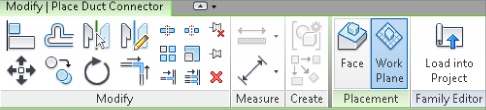
Figure 19.18 Placing a connector by work plane
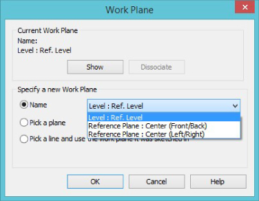
Figure 19.19 Placing a connector by work plane using the Name pull-down
The benefit of using the Work Plane option is that you can locate a connector anywhere on the plane. In case you created your reference plane in the wrong direction, and rotating it is not an option at this point because this would break the constrained geometry, you can still work around this limitation. Drag the reference plane grip past the other end, which will flip the orientation of the reference plane and the connector. Another option is to use named reference planes, choose the Pick A Plane option, and select the hosting plane from the drafting area.
The decision of whether to use the Face or Work Plane option for connectors depends on how you want to control the location of the connector. Whatever method you choose, once a connector is placed, you can adjust its properties so that the equipment family will behave as desired in your projects.
Duct Connectors
You can select the system type of a duct connector from the Options Bar, as shown in Figure 19.20, when you click the Duct Connector button on the Create tab in the Family Editor.
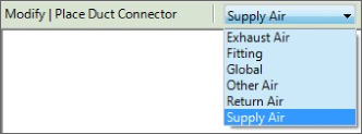
Figure 19.20 Defining the system type for duct connectors
The Global option enables the air system to be based on the system the equipment is connected to when the family is used in a project. A good use of the Global option is for fans, where the same fan family could be used for any system type. Fitting connectors do not have parameters to define air system behavior, and they are typically used on duct-fitting families to establish connectivity.
For air systems equipment, your duct connectors should be set with the properties that coincide with the behavior of the equipment that the family represents. Figure 19.21 shows the properties of a duct connector that has just been added to a family.
- Flow Configuration The Flow Configuration parameter sets how the flow is determined at the connector point, as shown in Figure 19.22.
- Calculated This option adds up all the flow values from objects downstream in the system.
- Preset This option is for direct input of the flow value at the connector point.
- System This option can be used if the flow at the connector point is a percentage of the entire flow for a system. With the System option, you will have to provide a value for the Flow Factor parameter. For example, if the equipment you are creating is used in a system with other equipment in your project and it provides 30 percent of the flow, Flow Configuration would be set to System and Flow Factor would be set to 0.33.
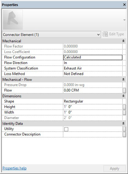
Figure 19.21 Duct connector properties
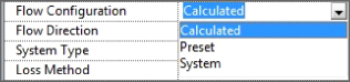
Figure 19.22 Flow Configuration parameter in duct connector properties
- Flow Direction
The Flow Direction parameter defines the direction of the air at the connector point.
- System Classification
System Classification determines which system type can be connected to the connector. For duct connectors, the choices are Supply Air, Return Air, Exhaust Air, or Other Air, or you can choose Fitting or Global.
Selecting Supply, Return, or Exhaust Air will mean you can connect to (or create) those types of systems, remembering that if you set up an outside air system type in your project using supply air, then you can only use a supply air connector for this system. Other Air is used for purely graphical representations of ductwork that will not create an intelligent system.
By selecting Fitting, you will remove all parameters other than angle, shape, and size, and the connector will act as a fitting, not able to calculate or preset a flow rate but instead just pass it through the family.
Global is used for families such as fans with connectors that can be used for more than one system category.
- Loss Method The Loss Method parameter allows you to assign either a coefficient, by placing a value in the Loss Coefficient parameter, or a specific loss, by placing a value in the Pressure Drop parameter. Keep in mind that these values are for the selected connector. If you have additional connectors in the family, you can also assign unique values to them.
- Shape Use the Shape parameter to define the connector as round, rectangular, or oval. The dimensions of a connector can then be assigned in the connector properties. Placing values for the Height, Width, or Radius parameters of a connector sets the size of duct drawn from that connector. If you want to change the size of the connector in the family properties, you can associate its dimensions with parameters created in the family, as shown in Figure 19.23.
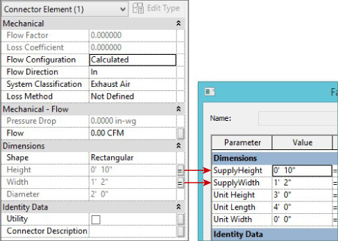
Figure 19.23 Connector dimensions associated to family parameters
- Utility The Utility parameter for a connector is used to define whether the connector indicates a utility connection. This allows for coordination when your project is exported for use in AutoCAD® Civil 3D® software. The connection points defined as utilities will be available in the exported file for coordination of things such as service entrance locations and invert elevations.
The dimensions of a connector can be associated with a parameter by clicking the + sign grip that appears near the connector label when the connector is selected in a view, as shown in Figure 19.24.
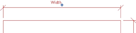
Figure 19.24 Associating parameters with a dimension using the + sign grip
It is important to establish the orientation of the Width and Height dimensions of a connector on your equipment. Otherwise, duct or duct fittings that are connected to the connection point may not be oriented properly. Connectors located on the side of the equipment should be easy to orient and configure. The height of the connector is the Z axis (up). However, connectors on the top or bottom surface of families can be a little tricky because there is no clear up direction. In those cases, testing the family in the project environment is best in order to see what makes the most sense.
The most common way to identify the “correct” orientation is to draw a duct and make sure that you are not getting any transitions. If you are getting transitions, you need to rotate the connector and change the mapped parameters for duct height and duct width. You can rotate a connector placed with the Face option by clicking and dragging it; however, this is an inaccurate method of rotation. Using the Rotate tool allows you to set a specific angle of rotation. If you use the Pin tool to lock the location of a connector, you will also not be able to rotate it. This can be useful if you find that you are accidentally clicking and dragging the rotation of your connectors when working in the Family Editor.
Pipe Connectors
Connectors for pipes can be placed on your equipment families in the same manner as duct connectors. You can find options for setting the system type on the Options Bar, as shown in Figure 19.25, when you click the Pipe Connector button on the Create tab in the Family Editor.
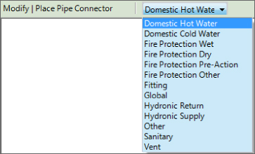
Figure 19.25 Defining the system type for a pipe connector
The properties for a pipe connector are similar to those of a duct connector, except that they deal with the flow of liquid instead of air. Because liquid flows differently, there are some different choices for the same parameters you would find in a duct connector:
- Flow Configuration The Flow Configuration setting for a pipe connector has options depending on the system type. Systems related to plumbing pipes have an additional Flow Configuration option called Fixture Units. This establishes that the flow at the connector is based on the value given to the Fixture Units parameter, as shown in Figure 19.26. Notice that the Flow parameter is not active when using the Fixture Units option for Flow Configuration.
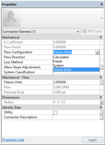
Figure 19.26 Properties of a pipe connector for plumbing pipe
- Radius/ Diameter The size of the connector is determined by the Radius or Diameter parameter depending on which is selected for the Round Connector Dimension parameter. If you are using the radius, then unless the connector does not need to change size with different family types, you should associate the Radius parameter with a family parameter for easy editing, as shown in Figure 19.27. Since pipe sizes are usually given as the nominal diameter of the pipe, you can also create a parameter for pipe size and use a formula to derive the radius from the size given. That way, your input is consistent with industry standards.
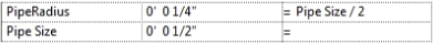
Figure 19.27 Pipe radius formula
- Allow Slope Adjustments
The Allow Slope Adjustments parameter lets you establish whether the pipe attached to the connector can be sloped. If you do not select the box, then when you apply a slope to pipe that is connected to the connector, you will receive an error message that the angle between the elements is too great and the pipe will become disconnected from the equipment.
If you draw a sloped pipe from a connector that allows for slope adjustment, the Pipe Connector Tolerance angle defined in the MEP settings of your project will determine the maximum angle that a sloped pipe can enter a connector. If the angle is exceeded, a straight run of pipe and an elbow fitting will be drawn from the connector prior to the sloped pipe.
Electrical Connectors
There are three kinds of connectors for electrical systems—conduit connectors, cable tray connectors, and electrical connectors:
- Conduit Connectors These can be added by clicking the Conduit Connector button on the Create tab in the Family Editor. The Options Bar provides two choices for conduit connectors, as shown in Figure 19.28.
- Individual Connector This option is for placing a single connection point in a specific location on the equipment. These connectors have properties for adjusting the angle and setting the radius of the connector.
- Surface Connector
Surface Connector is a unique and powerful option because it allows you to establish an entire surface of the equipment geometry as a connection point for conduit. Figure 19.29 shows a conduit surface connector that has been added to the top of an electrical panel family. This allows for the connection of multiple conduits at any location on the top of the panel. The Angle parameter can be set to allow for adjustments in the angle of the surface to which the connector is attached. This parameter is typically used in fitting families, but it may also have an application in an equipment family.

Figure 19.28 Selecting an individual or surface connector from the Options Bar
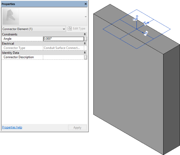
Figure 19.29 Conduit surface connector on the top surface of a panel family
When an equipment family with a surface connector is used in a project, conduit can be drawn to or from the surface by using the Conduit tool on the Systems tab. The surface containing the connector will highlight when you place your cursor over it. Selecting the surface will activate the Surface Connection mode, which allows you to drag the connector location to any point on the surface. This process can be repeated several times for the same surface connector, allowing you to model multiple conduits from your equipment, as shown in Figure 19.30. See Chapter 13, “Power and Communications,” for more information on modeling conduit.
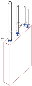
Figure 19.30 Multiple conduits from a surface connector
- Cable Tray Connector The Cable Tray Connector button on the Create tab in the Family Editor allows you to place a point of connection for cable tray. These connectors are similar to the individual conduit connector, having properties for the angle and for setting the height and width of the connector.
- Electrical Connector Clicking the Electrical Connector button on the Create tab in the Family Editor allows you to place a point of connection for wiring, which will also define the type of system in which the equipment can be used. The Options Bar allows you to define the system of the connector prior to placement.
When placing an electrical connector, you need to specify what electrical system type it is going to serve, as shown in Figure 19.31. Many properties of an electrical connector can be associated with family parameters for easy management and creation of family types.
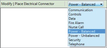
Figure 19.31 Defining the system type for the electrical connector
The Voltage parameter determines the distribution systems in your project where the equipment can be used. This must be coordinated with the value of the Number Of Poles parameter.
The Load Classification parameter enables you to assign a load classification to the connector that will determine the demand factor when the connector is used in a project. Even though you can create a new load classification in the family, and it will be available in the project when the family is loaded, it is not recommended to do it that way. You should map the Load Classification connector parameter to a Load Classification shared parameter. This way, you would be able to select the load classification from the project. Managing your load classifications from one place (in the project) is much more efficient than managing them in every family with an electrical connector. If you create custom load classifications in your families, they will be available in your project; however, you will not be able to delete them from the project!
Multiple Connectors in Families
Many MEP equipment families have multiple types of connectors. Your work environment may determine the connectors that you add to equipment families. For example, if your projects contain all MEP systems in one model, you may want to have electrical connectors in your HVAC equipment families that require electricity. If you have a separate model for each discipline, there is no need to have an electrical connector on any of the mechanical equipment families because the connection cannot be made through a linked file.
It is possible to link connectors in a family. This is useful when you want the system behavior to pass through from one connector to the other—for example, when you have a pipe fitting. Linking the connectors propagates system information through the fitting, so fluid flow in is related to fluid flow out of the fitting. You don't need to use the Link function for most families that contain parameters storing the fluid or air flow. However, the Link functionality is needed for fittings because they don't have those parameters and that's the only way to pass the flow through the fitting. You can link connectors by selecting one of the connectors and clicking the Link Connectors button on the Connector Links panel, as shown in Figure 19.32.
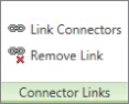
Figure 19.32 Linking connectors
Linked connectors will take on the Flow Configuration value of the primary connector. So even if you have a connector in the family that has a Flow Configuration set to Preset, if it is linked to a primary connector set to Calculated, the behavior of the connector in a project will be as if the connector is set to Calculated. You can tell whether connectors are linked in a family by selecting one of the connectors in the Family Editor. Red arrows will appear between linked connectors, as shown in Figure 19.33.
Figure 19.33 Linked connectors in an equipment family
The primary connector in a family is the first connector of each type added to the family and is indicated by crosshairs in the connector graphics. Figure 19.34 shows an equipment family with multiple types of connectors. You can change which connectors are the primary ones by clicking the Re-assign Primary button that appears on the Primary Connector panel of the contextual tab when you select a connector. Clicking the button allows you to select another connector, which will become the primary for that type.
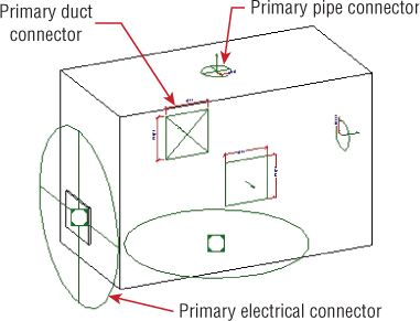
Figure 19.34 Equipment family with primary and secondary connectors
Naming connectors in a family makes it easier to understand which one you are connecting to when working in a project. You can name a connector in the Connector Description parameter in the connector's properties. When you use the Connect Into tool in a project on a family with multiple connectors, the connectors will appear in a list with their names so you can choose the correct one.
Now that you have learned about creating an equipment family, practice some of the basic skills by completing the following exercise. No matter what your discipline of expertise, these steps will help you become more familiar with the process of creating equipment families:
- Open the
Ch19_equipment.rfafile found at www.sybex.com/go/masteringrevitmep2015. - In the Ref. Level view, a corner of the equipment pad is at the intersection of the reference planes. Create a vertical reference line to the right of the vertical plane and a horizontal reference line above the horizontal plane, as shown in Figure 19.35. These lines will be used to define the length and width of the pad. Reference lines are mostly used if you need to control an angle parameter for geometry, such as a door swing.
Figure 19.35 Creating reference planes for the pad
- Create a dimension from the vertical reference plane to the vertical reference line. Select the dimension, and click the Label drop-down on the Options Bar. Select the Add Parameter option. In the Parameter Properties dialog box, name the parameter PadLength. Set the parameter to an instance parameter and click OK. Repeat the process for the horizontal reference line, using PadWidth for the parameter name, as shown in Figure 19.36.
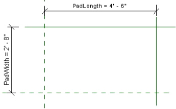
Figure 19.36 Creating dimensions and parameters for the equipment in plan orientation
- Open the Front elevation view. Draw a horizontal reference plane above the Ref. Level. Select the plane, and name it TopOfPad in its element properties. Create a dimension from the Ref. Level to the horizontal plane. Create an instance parameter for the dimension called PadDepth; see Figure 19.37.
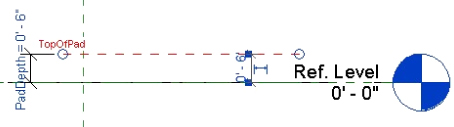
Figure 19.37 Creating dimensions and parameters for the equipment in elevation orientation
- Open the Ref. Level view. Click the Extrusion button on the Create tab and sketch a rectangle. Align and lock the sketch lines to the reference lines and planes. Click the green check mark button to complete the sketch. Open the Front elevation view. Align and lock the top of the extrusion to the TopOfPad reference plane drawn in step 4.
- Click the Family Types button on the Properties panel of the Create tab. Create a Yes/No instance parameter called Pad, grouped under Construction, as shown in Figure 19.38.
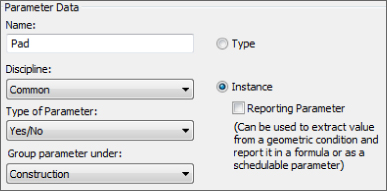
Figure 19.38 Creating a Yes/No visibility parameter
- Select the extrusion created for the pad. In the Properties palette, click the small box at the far right of the Visible parameter and associate the parameter to the Pad parameter created in step 6; see Figure 19.39. Click OK.
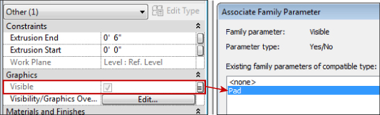
Figure 19.39 Associating the Yes/No visibility parameter with the Pad
- Open the Ref. Level view. Create a vertical reference plane 4″ (100 mm) to the right of the Center (Left/Right) vertical plane. Create another vertical plane 4″ (100 mm) to the left of the vertical reference line drawn in step 2. Create a horizontal reference plane 4″ (100 mm) above the Center (Front/Back) horizontal plane and another one 4″ (100 mm) below the horizontal reference line drawn in step 2, as shown in Figure 19.40.
You'll notice that in this step we broke a few rules. However, those rules will be more important from a consistency standpoint and for families that are having connectors that are hosted on the reference planes. If you are making such a family, you should consider keeping the Center (Left/Right) reference plane as is and creating two reference planes (one to the left and one to the right) for the UnitLength. This way, the name Center (Left/Right) will actually represent the reality.
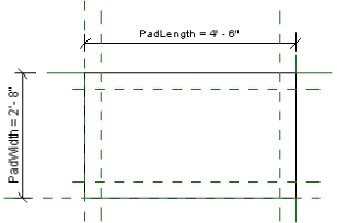
Figure 19.40 Creating reference planes for the equipment
- Dimension between the two vertical planes drawn in step 8, and create an instance parameter for the dimension called UnitLength. Repeat the process for the two horizontal planes drawn in step 8, with UnitWidth as the parameter name. Add a dimension for the 4″ (100 mm) distance from the initial vertical plane and the vertical plane drawn in step 8. Repeat the process for the 4″ (100 mm) distance between the initial horizontal plane and the one drawn in step 8, as shown in Figure 19.41. Be sure to lock the dimensions by using the padlock grip that appears when the dimension is placed.
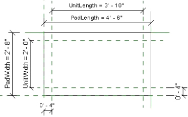
Figure 19.41 Creating dimensions and parameters for the equipment in plan orientation
- Click the Set button on the Work Plane panel of the Create tab. Select the TopOfPad reference plane from the Name drop-down list in the Work Plane dialog box. Click OK.
- Click the Extrusion button and sketch a rectangle. Align and lock the sketch lines to the reference planes drawn in step 8. Click the green check mark button on the Mode panel to finish the sketch.
- Open the Front elevation view. Draw a reference plane from left to right above the extrusion created in step 11. Name the reference plane TopOfUnit. Add a dimension between the TopOfPad reference plane and the TopOfUnit plane. Create an instance parameter for the dimension called UnitHeight. Align and lock the top of the extrusion created in step 11 to the TopOfUnit plane. Refer to Figure 19.42.
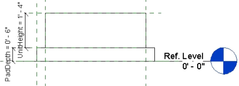
Figure 19.42 Creating dimensions and parameters for the equipment in elevation orientation
- Click the Family Types button on the Properties panel on the Create tab. Create an instance parameter called SupplyHeight and one called SupplyWidth using the settings shown in Figure 19.43. Give each of the parameters a value of 10″ (250 mm).
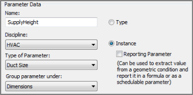
Figure 19.43 Configuring settings for a parameter
- Repeat step 13, creating parameters called ReturnHeight and ReturnWidth. Click OK to exit the Family Types dialog box.
- Open the default 3D view. Click the Duct Connector button on the Create tab. From the drop-down on the Options Bar, select Supply Air for the system. Place your cursor at an edge of the top extrusion to highlight the end face. You can use the Tab key if the desired face will not highlight when your cursor is on one of its edges. Click to select the face, and place the connector as shown in Figure 19.44.
Figure 19.44 Placing the supply duct connector in 3D view
- Rotate the view to show the opposite end of the extrusion. From the drop-down on the Options Bar, set the system type to Return Air. Select the face opposite from the Supply Air connector, and click to place the connector; see Figure 19.45.
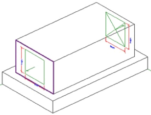
Figure 19.45 Placing the return duct connector in 3D view
- Click the Modify button or use the Esc key to finish placing connectors. Select the Supply Air connector, and access its element properties. Confirm that the Flow Configuration parameter is set to Calculated. Set the Flow Direction parameter to Out. Click the small rectangle to the far right of the Flow parameter, and then click Add Parameter to create a new parameter called SupplyAirFlow. Make it an Instance parameter and click OK twice to finish. Repeat the same process for the height and width of the connector. Click the small rectangle to the far right of the Height parameter to associate it with the SupplyHeight family parameter, as shown in Figure 19.46. Click OK to close the Associate Family Parameter dialog box.
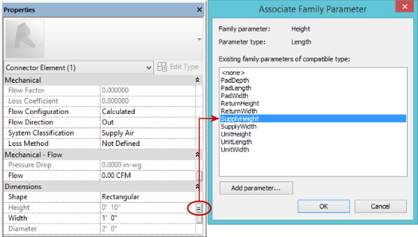
Figure 19.46 Associating a connector parameter to a family parameter
- Associate the Width parameter of the Supply Air connector to the SupplyWidth family parameter. Click OK.
- Select the Return Air connector in the view, and access its element properties. Set the Flow Configuration parameter to Calculated. Set the Flow Direction parameter to In. Click the small rectangle to the far right of the Flow parameter and click the Add Parameter button to create a new parameter called ReturnAirFlow. Make the parameter an instance parameter; fluid and air flow parameters should always be instance parameters because they should be adjustable values in the project environment. Associate the Height and Width parameters to the ReturnHeight and ReturnWidth family parameters.
- Click the Electrical Connector button on the Create tab. From the drop-down list on the Options Bar, set the system type to Power – Balanced. Place the connector on one of the side faces of the equipment extrusion. Click the Modify button or use the Esc key to finish placing connectors.
- Select the electrical connector and access its element properties. Set the Number Of Poles parameter to 3. Set the Load Classification parameter to HVAC by clicking the small box that appears in the value cell, as shown in Figure 19.47, and choosing HVAC from the Load Classifications dialog box.
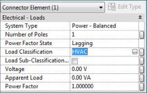
Figure 19.47 Configuring the properties of an electrical connector
- Click the small rectangle at the far right of the electrical connector's Voltage parameter to associate it with a family parameter. Because no family parameter is available, click the Add Parameter button at the bottom of the Associate Family Parameter dialog box. Create an instance parameter named UnitVoltage. Because the Voltage parameter was selected, the other properties of the parameter are already selected. Click OK to close the Parameter Properties dialog box. With the UnitVoltage parameter highlighted in the list, click OK to close the Associate Family Parameter dialog box.
- Repeat step 22 for the Apparent Load parameter of the connector. Name the family parameter UnitLoad.
- Click the Family Types button on the Properties panel of the Create tab. Set the value of the UnitVoltage parameter to 480. Set the value of the UnitLoad parameter to 5000. Click OK to close the dialog box. Select the electrical connector in the view, and access its element properties. Confirm that the values have been associated with the connector parameters.
You can save this family and use it to practice techniques for creating equipment. Load the family into a test project to test its behavior and usability.
Creating Clearance Spaces
Most MEP equipment requires some sort of clearance space for safety or maintenance reasons. Modeling the clearance spaces directly in your equipment families is useful for model coordination. Because the space is part of the family, any objects encroaching on the space will show up when you run an interference check of your model. You can choose to keep the spaces visible during modeling for visual reference to avoid such interferences. Even if you choose to turn off the visibility of the spaces, any interferences will still be detected.
Figure 19.48 shows an electrical panel family with clearance spaces modeled for the front of the panel and the space above the panel.
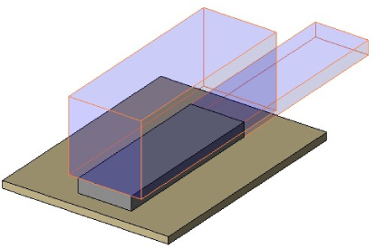
Figure 19.48 Clearance spaces in an equipment family
You can create clearance spaces by modeling an extrusion in the family that is associated with a reference plane at the appropriate face of the equipment. You can use other reference planes to control the size of the clearance space and constrain it to the equipment. In the example of the electrical panel, reference planes were created to constrain the top of the panel so that the front clearance space will always be 6″ (150 mm) above the top of the panel. The dimension for the space height was done in the extrusion sketch, as illustrated in Figure 19.49, which shows the plan view of the face-hosted family.
Figure 19.49 Clearance space reference planes in an equipment family
Once you have modeled a clearance space extrusion, there are properties that you can apply to it for visibility, as shown in Figure 19.50. In the panel example, a unique material type was created and applied to the extrusions for their semitransparent display. This keeps them from blocking out the actual equipment when shown in a model view.

Figure 19.50 Associating material for the clearance
A subcategory was created for the clearance space extrusions so they can be turned off in model views without turning off the equipment category. The subcategory is given a color for the edge lines of the clearance space extrusions to stand out from other solid geometry, as shown in Figure 19.51.
Figure 19.51 Display of the clearance extrusion in Visibility Graphics
You should always ask yourself the following question: “Just because I can do it, does that mean I really should do it?” In the preceding example showing you how to create a subcategory to control the visibility of the clearance separately from the rest of the geometry, it may seem like a great way to achieve what you need at the time. But as your library grows, you will find it hard to manage those custom subcategories in individual families. Having a standard for when to create them and what to name them can help. In addition, you should consider other available options. In this case, you could assign the clearance to the Hidden Lines subcategory, which comes with most 3D-based Revit family templates. You could also use the Visibility parameter to control when it is turned on or off. Essentially, you can achieve similar functionality by taking a different route.
Although having solid geometry in an equipment family to represent clearance spaces is useful for interference coordination, you may not want to have the solid geometry displayed in plan views. Model or symbolic lines can be used to represent the clearance space for plan views. The visibility of these lines can be controlled by a Yes/No type parameter or by a subcategory. Figure 19.52 shows clearance space lines in the Front elevation view of the panel family. The lines exist in the Front elevation view so that they will be visible in plan views when the panel is attached to a vertical host.
Figure 19.52 Lines representing clearance space in a family
Another option for adding clearance spaces to your equipment is to create unique clearance-space families. These families should be categorized as mechanical or electrical equipment families, but you could categorize them as any of the available subcategories, depending on how you want to control their visibility. In a project file with worksharing enabled, a workset could be created for equipment clearance spaces, as an option for making it easier to control the visibility of all equipment in a view. There is a downside to relying on worksets for visibility control, however, because you may also be using worksets as an option to load selected parts of the project. This can lead to confusion, not just within your company's project team but also for those working collaboratively with you.
Clearance space families can be face-hosted families for easy attachment to the solid geometry of your equipment families. Consider making individual families with the dimensions for each unique type of clearance or for specific types of equipment.
The example of displaying solid geometry (the clearance) with linework can be applied to most families' solid geometry. Displaying lines instead of geometry will improve your overall project performance with your families because Revit will need to regenerate lines instead of surfaces. This can be especially noticeable for round objects such as pipe connectors and their extrusions, because the software will try to simplify those round surfaces by breaking them down to multiple flat surfaces.
Adding Parameters and Constraints
The key to having equipment families that are usable in the early stages of your designs is to have families that are easily modified to meet the demands of frequent changes to your project model. Using parameters gives you the flexibility to change not only the size of equipment but also the values of connectors.
Three simple dimensions can define most equipment: length, width, and height. By using these parametrically, you can be confident that your equipment families occupy the space required for them in the model, even if they do not look exactly like the object they represent. Be consistent with your use of these parameters and particularly the naming convention you use. They do not need to be shared parameters unless the information is to be included in schedules. However, you could create them as shared parameters for consistent naming. Because there may be other dimensions in your families, it is best to give these parameters a descriptive name, such as Unit Length or Equipment Width, to distinguish them as the overall size. Of course, having these parameters in your families is not enough; you need to have the family geometry associated with them.
MEP equipment schedules vary in size and information, not only from one company to another but even in the same company, depending on the project standards or client demands. Mechanical equipment schedules are particularly difficult to manage without the proper use of parameters in your equipment families. The use of shared parameters is necessary for scheduling the systems information required from equipment schedules. The problem is that all mechanical equipment families are in one category.
To avoid having families with unnecessary parameters, it may be best to apply your shared parameters directly in the equipment families instead of using project parameters. That way, you can be sure that you have only the parameters required for the scheduling of the specific families in your mechanical equipment schedules.
Connectors have parameters that you may need to change based on the performance of your engineering systems. Creating parameters in your families with which the connector parameters can be associated allows you to change the connector values without having to open, edit, and reload your families. The main thing to remember when creating these parameters is that they must match the units of the connector parameter in order for them to be associated. For example, you cannot associate a connector's Voltage parameter with a number or integer parameter.
When you are creating equipment, you will often find yourself creating many types of the same equipment at different sizes, such as, for example different sizes of a terminal box based on inlet sizes. This is where type catalogs can be helpful. Each parameter in the type catalog must be a valid Type and use a valid unit selection. Also each parameter must actually be present in the family before the type catalog can insert the desired values. See Chapter 6, “Parameters,” for more information on how to set up type catalogs.
For more information on parameters, see Chapter 6, and for more information on schedules, see Chapter 7, “Schedules.”
The Bottom Line
- Create MEP equipment families The ability to create the types of equipment families needed for accurate modeling of components and systems is a major factor in the success of your Revit projects.
- Master It MEP equipment can be quite complex in its structure. Complex geometry can have an adverse effect on model performance. What are some ways to model equipment in its simplest form yet still convey the proper information on construction documents?
- Add connectors to equipment for systems Adding connectors to equipment families will make them functional for use in the design of engineering systems.
- Master It It is important to know how your equipment families will be used in your projects from an engineering standpoint as well as for model coordination. Explain how connectors determine the behavior of an equipment family.
- Create clearance spaces for equipment Space for safety and service of equipment is crucial to building design. The ability to coordinate clearances around equipment improves project quality and can reduce construction and design cost.
- Master It Equipment families with built-in clearance spaces allow you to determine quickly and easily whether the equipment will fit into your project model. Describe some options for controlling the visibility of clearance spaces so that they are not shown when not needed.
- Add parameters to equipment Parameters in your equipment families can be useful for creating schedules in your Revit projects that report data directly from the equipment used in the design. Family parameters can enable you to make equipment families that are changeable without having to create new families.
- Master It Shared parameters must be used in your equipment families if you want to schedule the data they provide. If you are creating parameters for parametric behavior of the solid geometry, do they also need to be shared parameters?