
Floors and roofs are two of the main elements for any building project, and you must contend with them when you are modeling a structure. The various floor construction types that you will encounter on a regular basis include concrete slabs-on-grade and supported decks constructed with concrete and metal, wood, or formed concrete. Along with modeling the basic slab or deck profile, you will be required to add slab edges, depressions, ramped floors, and openings to your project in order to accurately develop the design.
Although the techniques seem similar, roof modeling is quite different from floor modeling because you will be spending a lot of time and effort sloping the roof for drainage purposes. Roofs come in many forms, from a residential wooden Cape Cod–style roof to a commercial roof that warps from ridges to drains. A roof is one of the most difficult elements to model in your projects; therefore, the tools and workflow required to create and edit roofs must be up to the task. It is essential to gain a solid understanding of how to model these difficult elements to maintain the integrity of your model.
Revit Structure has many excellent tools to add to your modeling tool chest that help in the creation of these floor and roof entities. In this chapter, you will see those tools in action.
Of course, the slabs will have reinforcing bar or mesh in them, but you will learn how that works later in the book in Chapter 12.
In this chapter you will learn to:
The first part of this chapter will deal with slabs-on-grade as well as elevated slabs and decks. An understanding of their basic properties and the tools used in their creation is an essential step to mastering Revit Structure. In this section you will have a chance to work with these elements in order to create various slab conditions. You will learn how floor types are made within the foundation slab and floor system families and how you can modify them to satisfy the many conditions that you will be required to model in the virtual environment. To that end, you will examine many forms of supported decks as well as slabs-on-grade.
You can find the Slab command on the Foundation panel on the Home tab of the Ribbon; you use the Slab command to make slabs-on-grade and slab edges. When you click the Slab icon, you enable Sketch mode. Sketch mode isolates you from the rest of the model as you are working on the slab so that you can create its outline without disturbing other elements. Sketch mode is used not only for making slabs but for many other functions as well. You should have a thorough understanding of it if you want to use Revit Structure effectively. You will find the Floor command on the Structure panel of the Home tab of the Ribbon; the Floor command is used for making supported decks. For slabs supported on ground, use the Slab function on the Foundation panel.
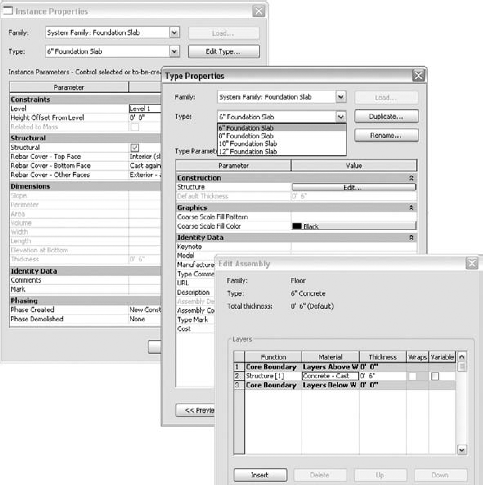
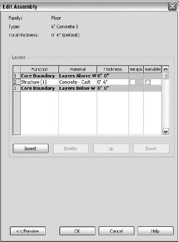
As discussed in earlier chapters, most elements that you model have Instance and Type parameters (see Figure 5.1). The Type parameters apply to every occurrence of an element of that type in your project. In the case of slabs, an example of a Type parameter is the thickness of the slab. The Type parameters for defining the slab structure are found in the Edit Assembly dialog box and include the following:
Function
Material
Thickness
Wraps
Variable
We will discuss those more in a bit. Instance parameters apply to a particular insertion of an object. An example of a slab Instance parameter is the height from the level to which the slab is attached. Rebar Cover is an important group of Instance parameters for slabs.
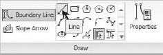
Once you're in Sketch mode you will create the slab by using the available suboptions found on the Draw panel: Boundary Line and Slope Arrow. Boundary Line (see Figure 5.2) offers the following Draw options:
- Line and other sketching options
Use this option to sketch the boundary of the slab with lines or using a variety of common forms.
- Pick Lines
Use this option to pick other lines or reference planes that define your slab boundary.
- Pick Supports
Use this option to select beams or girders.
- Pick Walls
Use this option to select walls that support the slab.
- Slope Arrows
Slope arrows permit you to define the desired slope of an entire slab or a portion of slab. The head and tail define elevation change over a distance, the distance between the head and the tail. The slab will slope from tail to head, and the slope of the slab will change over the length of the slope arrow regardless of where the slab edges are. This means I could draw a 10′ long slope arrow and offset each end 10′, and the slab will "tilt" overall, but between the head and the tail it will slope exactly 10′. This is a subtle difference, but functionally this means that I can define a specific slope in a critical area without regard for what it does at the extremes of the slab and find out what that does to my assumptions about that particular area of the slab.
Using one of those methods, you draw the boundary of the slab. The slab boundary lines must be a closed sequence of lines or arcs, so you must be sure that your elements are trimmed and connected to each other. Otherwise, Revit Structure will not allow you to complete the sketch.
Once the boundary has been established, you will assign a slab type to the element (see Figure 5.3) by clicking Floor Properties on the Element panel of the Modify Slab tab and then choosing the desired type from the drop-down list. Some slab types are available as defaults, and some you will need to create yourself in the Type Properties dialog box. A good template will have the right collection of slab types ready and waiting for you. See Chapter 2 for an explanation of templates.
Within the foundation slab and floor families, you can create many types of floors. Let's now explore the workflow you will use to produce these elements in various forms, starting with a slab-on-grade.
The most basic type of slab you can make is a simple slab poured against the ground, known as a slab-on-grade, or a foundation slab. You may have gotten out the hoe and wheelbarrow and mixed some concrete in your own backyard at some point to make a new slab for parking, or a basketball court, or a walkway perhaps. You began by laying out the boundary with boards or digging and letting the earth be your form, adding in some reinforcing if needed, and then pouring the concrete. You may also have had to block out certain portions to create openings or depressions. That is exactly what you have to do here: create a slab boundary and then apply a certain type of slab to it.
Let's examine the general method that you will use to create a slab-on-grade within Revit Structure:
Click the Slab icon and then choose Foundation Slab from the drop-down list to enter Sketch mode.
Once in Sketch mode, you use the various Draw tools on the Draw panel. You can choose to either draw the lines or other shapes or select an existing line that will be duplicated in the same location.
In the Floor Properties dialog box, choose an appropriate slab type for your project, like a 6″ concrete slab.
Complete the slab boundary (see Figure 5.4).
If necessary, use the Trim command to ensure that all lines are connected; otherwise you cannot complete the sketch.
Click the Finish Floor icon at the right side of the Ribbon, and the slab is complete.
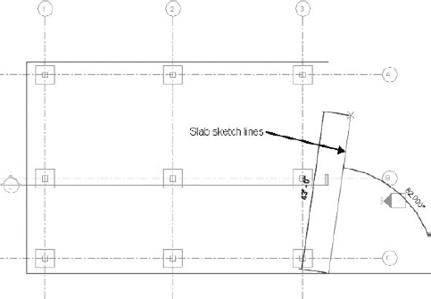
The slab lines can be locked to grid lines or to the architectural stud line in order for the slab lines to adapt automatically to a change in size or location. But you need to be careful that you don't over-constrain the model because performance could suffer. Sometimes you might not want to lock your sketch lines to their boundary for this reason. It takes some time and experimentation to get a feel for those limits.
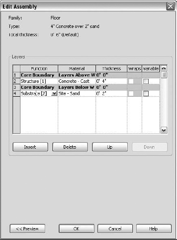
That was easy enough to do, but what if you need a 4″ thick slab for your project, and you want a 2″ layer of sand below it? In that case you will create a new slab type by duplicating the existing 6″ concrete slab and then adapting its properties. You will also add a new layer to the 4″ slab. The following section shows how the basic procedure works.
Creating a new slab type is not very difficult at all. Follow these steps:
Once you enter Sketch mode, access the Floor Instance Type properties.
Click Edit Type and then Duplicate to create a new slab.
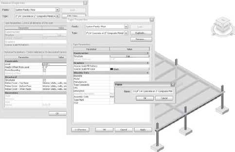
Give the slab a name, and then click on the Structure tab, which will bring up the Edit Assembly dialog box (see Figure 5.5). This allows you to alter the deck or slab structure.
Now you can adjust the Material type and the Thickness value of the new slab.
When you click into the Material parameter, the Materials dialog box opens, and you can choose from various materials, alter the existing materials, or create new materials for that layer. Layers such as sand or metal deck can be added here (see Figure 5.6).
The different layers are placed inside or outside the core boundary as required.
The Variable field of the Edit Assembly dialog box allows your layer to vary in depth, for instance, for the purpose of drawing a sloping roof deck layer.
Now that you have seen how to add a slab and create a slab, let's look at the procedure to edit one already created and placed in your project.
Editing the slab once it has been created is not difficult. Just follow these steps:
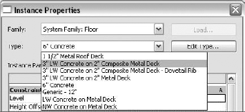
To change the slab type, select the slab and then choose a new type in the Type Selector.
To edit the boundary of the slab, select the existing slab.
Click Edit Sketch on the Edit panel of the Modify Structural Foundations tab, which puts you back in Sketch mode.
Click Finish Floor on the Modify Structural Foundations Floor panel.
We'll put all this together in the next exercise, where you create a new multilayered slab element for your project.
Exercise: Creating a Slab-on-Grade
In this exercise, you will create a basic concrete slab-on-grade with a vapor barrier below it. First, you sketch a basic rectangular shape. Then, you create a new slab type consisting of 4″ of concrete with 2″ of sand beneath it for the shape.
To sketch the basic slab shape:
Open a new project in Revit Structure.
In the Project Browser, double-click on Level 1 to open the view.
On the Ribbon click the Home tab.
Choose Slab

Click the Rectangle icon on the Draw panel.
In the drawing area draw a rectangle for the slab boundary; any size will do for this exercise.
Now let's create the new slab type:
On the Ribbon click the Floor Properties icon.
In the Type pull-down list, select 6″ Foundation Slab.
Click Edit Type; then in the Type Properties dialog box, choose Duplicate.
In the Name dialog box, type 4″ Foundation Slab over 2″ Sand, and click OK.
In the Structure field click Edit.
In the Edit Assembly dialog box, change the Thickness to 4″.
Click the Insert button to create a new layer below the concrete.
Click the Material field and change the material to Site-Sand. Click OK, and then click OK again to exit.
Click the Thickness field for the sand layer and change the value to 2″.
Click OK in the remaining dialog boxes.
Click Finish Floor to complete your slab. Then go to a 3D view and check out your new slab.
Leave your model open for the next exercise.
Creating the basic slab-on-grade is not too difficult. But each slab will have an edge condition that will also have to be modeled. For the basic slab-on-grade that we have been working on, there will most likely be a thickened slab 12″ to 18″ in depth around the perimeter of the slab, with a bearing surface of 8″ to 12″ (see Figure 5.7).
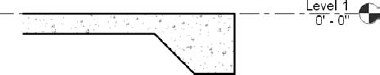
Of course, that is a simple slab edge shape in which you can add a new type to the default slab edge family. You can also start your own profile family file and create any shape you might need as long as it is a single closed boundary of lines. You can then add constraints to the basic shape to make it become a parametric family whose shape can flex to different sizes. The existing families are a good place to start by reverse engineering how they were built.
Figure 5.8 shows a more complicated slab edge profile. For this advanced case you will need to create a new profile family since the shape varies so much from the default slab edge family.
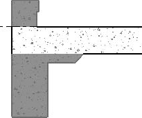
One important point to remember is that you want the slab edge material to be the same as the slab material so that when you cut a section, the final display of the slab and edge appears monolithic.
The parametric nature of Revit Structure families means you can create and manage literally thousands of modeling shapes in a well-coordinated, easy-to-understand fashion. The Slab Edge function is located on the Ribbon on the Foundation panel in the Slab drop-down list. The shape of the slab edge is controlled through the use of slab edge profile families. These families are parametrically driven, giving the profile family the ability to flex to different sizes of the same basic shape. There are limited types loaded into the default template, so you will most likely need to add new profile types, which you will learn to do later in this chapter. For now, let's explore the basic procedure for adding a slab edge type to your project.
On the Home tab of the Ribbon, on the Foundation panel in the Slab drop-down, click Slab Edge.
Then select the slab edge type you want to use from the Type Selector.
To add the slab edge to the slab, just begin clicking on its edges and make your way around the slab. The slab edges can be connected into chains of similar edge types if different types are required for different parts of the slab.
To start a new set of edges, click the Finish Current icon on the Profile panel, choose a new profile from the Type Selector, and then start picking edges again. By making groups of slab edges, you can better control and define their behavior, especially if you have multiple types.
When viewed in section, the slab edges will "clean up" or appear monolithic with the foundation slab as long as the two elements have the same material, so make sure when you create the edge type that its material matches your slab material.
Now you've completed your basic slab edge. But during the period while you are designing your structure, you will undoubtedly need to revise the slab and its edges several times. You might want to eliminate one or more segments that you have added. How do you do that?
First, you select a slab edge segment that you want to change.
On the Options bar click the Add or Remove Segments button.
Then select the edge that defines the segment you want to remove or an edge where you want to add a slab edge.
After placement, the slab edges can be offset vertically or horizontally from the slab element. To offset the slab edge, follow these steps:
You can also flip the slab edge profile 180 degrees in plan view:
First, select the segment to flip.
Then click the double-arrow control that appears next to the slab edge and that will mirror the segment about the edge of slab.
The control will flip all the connected slab edges as well. If you need to flip just one of them, then you will need to define it by itself first.
In practice, you will contend with many different types of slab edges, and it can become difficult to keep them accurately modeled and displayed. This tends to be a time-consuming activity, but in order to display the model accurately, it is a necessary concern. Let's look at the profile-creation process a little closer and see how a new profile type can be made and loaded into your project.
One of the real powers of Revit lies in the parametric nature of its model and annotation families. You should learn to create parameters in your own families that allow the family elements to flex into new shapes. But if you get overly frustrated in your first attempt to do this, stick with creating the single-shape family. Later you can evolve to the higher-level creation process where your families become more parametric in nature.
Figure 5.9 shows the profile family for the edge of slab. It could be just a single four-sided shape for use as a profile. You could then create many different files, each with a similar four-sided shape but with different widths and thicknesses, such as 12 × 36, 10 × 20, or 18 × 36, all in a library of edge types. AutoCAD works that way. That approach is not parametric. Having one profile family represent similar shapes with the ability to flex the shape easily into new types is the parametric approach. Revit Structure works that way.
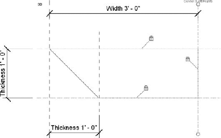
Figure 5.9. Parametric constraints in the slab edge family file lock the shape lines to reference planes.
Next, let's see how to convert a simple single shape (see Figure 5.9) to a parametric one. You would do the following in the Family Editor:
Draw reference planes where a surface edge will be placed.
Draw lines along the reference planes to create the shape of the slab edge.
Lock the lines to the reference planes as you are drawing them. You can also lock the ends of the lines to the reference planes.
Create dimension strings between the reference planes.
Select one of the dimensions, right-click, and choose Edit Label. In the resulting pull-down box, click Add a Parameter, or choose to edit an existing one.
In the resulting dialog box create or edit the parameter label.
Finish attaching flexible parametric labels to the dimensions, which act either as Type or Instance parameters within the family.
Create a new type.
Flex the model to make sure it is working properly.
This general process gives you an insight into how to adapt and extend your modeled shapes into more generalized families.
If you have to make a new slab edge type in your project, most likely you will also have to add a new type to the slab edge profile family because they work together. The default slab edge profile family can be found under Profiles on the Project Browser. The next exercise will show how this is accomplished.
Exercise: Creating a Slab Edge Type and Adding It to Your Slab
In this exercise, you will create a new slab edge type from the loaded slab edge profiles, and then you will add it to the slab that you made in the previous exercise. When you complete the exercise, make a section through the slab and check to see if the slab edge displays correctly.
First, have a slab available in an open model from the previous exercise, or create one in a new model; a basic four-sided slab is sufficient. You can now create a new slab edge type in the profile family:
Navigate to Project Browser
In the Type Properties dialog box click Duplicate.
Name the new profile type 30″×20″; click OK.
Enter the values 30″ for the Width and 20″ for the Thickness.
Click OK to exit the dialog boxes.
Navigate to Project Browser
In the Type Properties dialog box click Duplicate; then give the new type a name: Thickened 30″×20″.
In the Profile drop-down list pick the new profile type you created: Slab Edge - Thickened 30″×20″.
Set the Material of the slab edge to Concrete Cast-in-Place.
Click OK to exit the dialog box.
Now you can add the new profile to a slab edge type by doing the following:
On the Home tab of the Ribbon select Slab from the Foundation panel and choose Slab Edge from the drop-down list (or navigate to Project Browser
On the Ribbon click Element Properties; then choose Type Properties from the drop-down list.
Click Duplicate and give the new slab edge a name.
Assign the new slab edge type the name Thickened 30″×20″. Then click OK.
In the Type Profile field, select the Slab Edge - Thickened 30″×20″ profile type that you created.
Click in the Type Material field to display a small button; then click it to open the Materials dialog box.
Select Concrete – Cast-in-Place Concrete, and click OK in each dialog box to finish your editing.
Click each edge of the slab successively to form a chain of edges around your slab. Click Finish Profile on the Profile panel of the Place Slab Edge Ribbon tab.
Click Modify on the Selection panel of the Place Slab Edge tab of the Ribbon (this completes the command).
On the View Control bar change the view to Hidden Line, if it isn't already, to show correctly the inside bottom edge as hidden below.
Select the slab edge you just created.
On the Options bar, click the Add or Remove Segments button.
Click on the right and left edges of the slab to remove those two segments.
Remember that we suggested you create a section through your slab to see if it turned out as you hoped, similar to Figure 5.7.
Now that you have learned how to use foundation slabs, let's move on to the next discussion, which is about supported slabs and decks.
The next important feature we will explore is working with floor decks in Revit Structure, with a focus on the nature of multilayered decks. Here are some examples of floor decks you might encounter in your projects:
A steel project might have a floor deck consisting of 3

A wood floor deck on the second floor of an elementary school could be 2″ of lightweight concrete fill over a ¾″ layer of wood sheathing.
A concrete flat slab over a basement could have fill topping at the street level for drainage purposes.
The process of creating different types of floor decks (see Figure 5.10) and placing them is the same as for the foundation slab, but with a few differences, most notably creating composite metal decks. The metal deck family has several default types, as shown earlier in the chapter. You learned how to add layers when you added a layer of sand below the slab-on-grade. Now let's see what we need to do to create a metal deck slab.
The process of making steel and concrete composite decks is much the same as for the basic slab-on-grade type except the deck is multilayered. It is important to define a composite deck type in such a way that it can be cut in section and accurately show the fluted metal deck filled with concrete. This helps make your section views more complete, which means that finishing them will require much less effort. Let's see how to make the slab:
In the Project Browser scroll down to Families, and expand the list of families by clicking on the plus (+) sign on the left. Scroll to Floors and expand the list again and you'll see a few types.
From the list of Floors double-click on one that seems close to what you need. The Type Properties dialog box opens.
Click the Duplicate button, and then give the new deck a name.
In the Structure parameter, click the Structure button. Depending on which floor you choose to duplicate, you may need to add a layer. Refer to Figure 5.11 to see whether you do.
If necessary, within the core boundary insert a layer for your concrete.
If necessary, insert a layer for your metal deck.
In the Function column for the bottom layer, click in the Function field and choose Structural Deck [1]. This is a special feature of Revit Structure to define the relationship between this layer and the layer above so the concrete can blend into this layer.
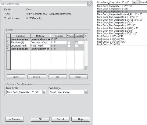
Choose a deck profile from the Structural Deck Properties area (see Figure 5.11) at the bottom of the dialog box. Those profiles are families and can be edited separately if desired.
From the Deck Usage drop-down list, choose Bound Layer Above. This choice causes Revit to include this layer as part of the layer above it; thus, the entire thickness of this slab is defined in that layer. The deck profile is bound into the layer above. The Standalone deck option treats the deck as a separate entity, making the deck thicker than required.
If the structural deck profile you want does not exist, you can create one by editing the deck profile family and adding new types, similar to the way you did with the slab edge profile.
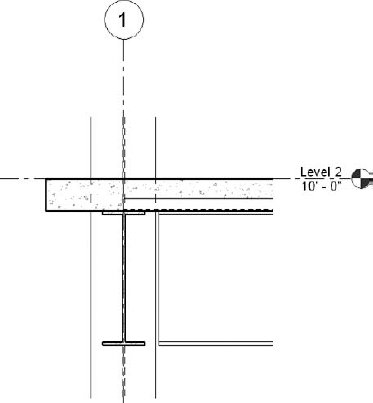
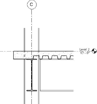
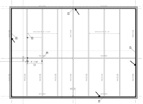
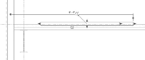
Edge conditions are a major consideration for floor decks. Typically the metal deck stops at the support girder, and then only concrete extends out to the inside face of the stud supported by an angle or a bent plate (see Figures 5.12 and 5.13). In order to accurately represent the edge condition in your model, the deck family has to accommodate the discontinuity of the metal deck. Fortunately this is not difficult to accomplish. Each boundary sketch line for a slab has a property for Cantilever - Concrete or Steel. To configure this you need to work in the slab's Sketch mode. While in Sketch mode select one of the boundary lines. Then on the Options bar, set the concrete or steel cantilever distance (see Figure 5.14) as required for your project. You should notice that a positive value makes the extension go to the inside of the support line, and a negative value makes the extension go to the outside of the support line.
The span direction for a supported slab is another important practical element to consider. When the deck is first created, a span direction symbol is added. The half arrows shown in one direction indicate the strong direction (the span, flute direction) of the deck. You can also add the span indicator at any time by selecting the Annotate tab from the Ribbon and from the Symbol panel choosing Span Direction. If you select the span direction symbol that is already placed and rotate it, you can change the direction of the deck for a placed deck element. This will be essential in order to show the deck correctly in your section views.
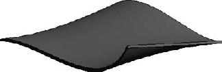
Now that you have started to get a feel for creating floors, you will find that roofs are created in much the same fashion. The big difference lies in the many varieties of wood, steel, and concrete roof shapes that you must be prepared to accommodate in your project. It could require a residential gable roof, a saltbox roof, a flat commercial-style roof deck, or perhaps even a freeform, wavelike shape.
To contend with these possibilities, you will use special tools to help create and slope your roof elements. You will then also be able to combine different roof shapes and slopes into one roof system. In Chapter 7, you will learn how to best frame your roof for these different roof conditions. Of paramount concern in constructing your roof system is the ability to edit the roof sloping and the framing that supports it as easily as possible as the design progresses.
As you will see in Chapter 7, a sloped and warped roof will necessitate that your beam and girder system supporting the diaphragm flex automatically when you edit the diaphragm. Since each beam will most likely have a different elevation at its end, editing a complex roof shape can be time consuming. Therefore, you will need to give special consideration to your approach.
One big issue that often crops up in many projects concerns the interaction with the architectural designers as you develop the roof for your model. If the architects still use 2D techniques, they will normally not be too concerned in the design development stage about the slope of the roof. But for the person doing the modeling, that can mean trouble. Best practice is to try to work with the architect to get an idea of ridge and drain locations that you can then readily edit later in the project. To create your roof element, you will need enough information about the sloping so that you can at least get a semblance of the roof system put into place. If you simply begin by creating a flat roof, you will undoubtedly be forced later to scrap it and start over. Also, keep in mind that the integrity of the model is compromised by showing just a flat roof. Ignoring the true slope of the roof means the greater the span of the sloping structure, the worse the compromise will be and the greater the potential for conflicts.
Now let's take a close look at the techniques used to model different roof conditions. The two main areas we will focus on are the geometry of the roof diaphragm and the creation of various roof types to apply to that geometry.
The roof family, like every other family in Revit Structure, is populated with different types. These types are created in much the same way as floor types were created earlier in this chapter. The two basic families of roof types are basic and sloped glazing. We will concentrate on the basic type. Sloped glazing roof types are appropriate for creating a greenhouse or a skylight structure and work similar to curtain walls, except these can slope.
Let's now examine the process of creating a new roof deck. The Roof tool is on the Architect panel of the Architect & Site tab of the Ribbon. There are six related tools on its drop-down menu. We will concentrate on two: Roof by Footprint and Roof by Extrusion.
Let's first see how to create a new roof deck using the Create by Footprint option. With this option you work in a plan view and draw the boundary line for the roof deck.
Go to your roof level view, and then on the Ribbon click the Architect & Site tab, select Roof, and then select Roof by Footprint.
On the Ribbon in the Element panel click Roof Properties, which displays the Instance Properties dialog box.
Click Edit Type, and in the resulting Type Properties dialog box, click Duplicate.
Give the new roof type an appropriate name.
In the Type Properties dialog box under Construction, click the Edit button in the Structure field.
In the Edit Assembly dialog box, you will create the different layers of the deck, such as a metal deck layer and a fill over that.
A typical roof assembly fill might be a lightweight concrete fill, wood sheathing, or solid insulation. These components of the roof assembly will be within the core layer. Create an assembly fill layer by clicking the Insert button and assigning values for Material and Thickness.
Use the Up and Down buttons to move the layers as needed to their correct location within the roof element.
Create other nonstructural layers, such as roof membranes, outside the core boundary.
Check the Variable box to the right of each layer to free up that layer so that you can vary its depth.
The bottom of these layers will remain constant, while the top can vary. First set the minimum thickness, and then check the Variable box to have thicker portions than the minimum setting.
Click OK in all remaining dialog boxes.
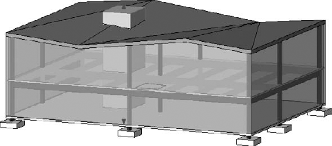
That is how you create a new roof deck type. Transparencies are often applied to the decking materials so that you can look through the roof deck and see the framing below. Set the Transparency value to 10% and notice how much more of the structure you can see in your 3D views. For structural presentations it really helps. Now it is time to move on to sketching the actual deck geometry.
As stated earlier, sketching roof geometry is one of the most challenging things you will do when modeling with Revit Structure. Let's start by looking at some of the easier forms and work our way up to ones that are more difficult. First, let's create a simple sloped gable roof (see Figure 5.15).
The basic gable-style roof (as shown in Figure 5.15) is not difficult to model. In general, just do the following:
On the Ribbon, click the Architect & Site tab, choose Roof, and select Roof by Footprint.
You will enter Sketch mode, where you can draw the outline of the roof; the lines represent the eave or edge of the roof.
Click Lines on the Sketch menu.
On the Draw panel of the Ribbon, the basic Sketch tools are available, so you can draw or select the outline to define the footprint you want.
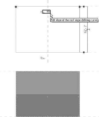
Once you create the outline, select the lines that will be at the top or base of the sloped surfaces—in this case, the line on each long side of the roof.
On the highlighted lines, you will see a triangle slope symbol next to the line that represents the slope value (see Figure 5.16). When you hover the mouse over the slope value, a box appears around the value. Click in the box, and you can enter a new slope value.
Once you have a closed boundary sketch, you can click Finish Roof on the Roof panel of the Ribbon to complete the roof.
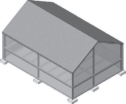
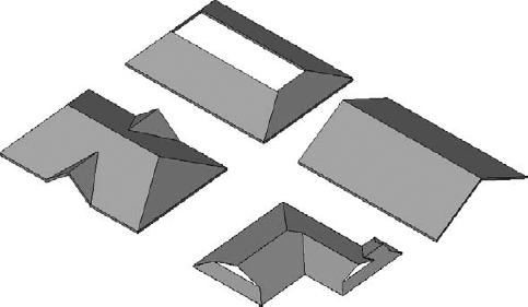
Figure 5.17 shows a more complicated hip roof that slopes in four directions and adds dormers on two sides.
The method to create a roof with hips and dormers in your project similar to the one shown in Figure 5.17 involves the following steps:
In Sketch mode, as you did on the simple roof, add lines for the four sides, set each to Define Slope, and then adjust each slope angle accordingly.
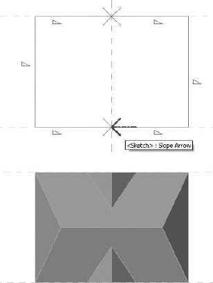
You need to use slope arrows to create the dormer portions. Slope arrows indicate the direction and extent of a sloping deck line, such as our dormer. There is a tail and a head; the arrow is the head.
The roof sketch needs individual line segments to define each portion of the gable dormer. On the top and bottom lines of the roof footprint, use the Split tool to break the existing sketch line into a total of four lines, each representing the basic roof or dormer horizontal length. The outside pair represent the slope of the main roof. For the purpose of this discussion these should be equal in length. The inner pair should also be equal and indicate the length of the gable and meet at the ridge of the dormer.
Click Slope Arrow on the Draw panel of the Create Roof Footprint tab. You will sketch the slope arrow from the eave to the ridge, up the dormer.
Sketching over the dormer lines, add the slope arrows with each arrow pointing toward the middle, the ridge of the dormer. If it helps, imagine where each segment of the roof sketch meets is a hinge that will allow the roof to slope, or change direction.
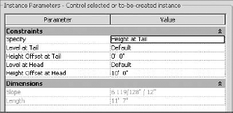
Select both slope arrows and then click the Properties button on the Draw panel of the Ribbon.
Adjust the properties to fit your dormer configuration (see Figure 5.18).
Repeat as necessary for the slope arrows on the other side of the roof. You can also set the slope arrow to use a Slope value like that of the roof sketch lines as opposed to entering a starting and ending elevation, as shown in Figure 5.18.
When you have finished, click Finish Roof on the Roof panel of the Ribbon.
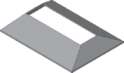
Now let's look at a roof with a cutout portion, such as a mansard roof.
Another common roof shape you might encounter involves cutting out a portion of the roof to create a cutoff condition, such as for a mansard roof, or to prepare for a two-pitch roof (see Figure 5.19). The general process for this example is the same as for the roof that you just created. Once you complete the basic shape, select it, and then click the Element Properties tab next to the Type Selector. In the Element Instance Properties dialog box, you can add a value to the Cutoff Level parameter to establish a point above the base of the roof where you would like it to be cut.
Are you getting the idea of how this works yet? Play around with these various options until you feel a little more comfortable with how this all functions. Using these various roof tools, you can create a complicated roof diaphragm configured as shown in Figure 5.20.
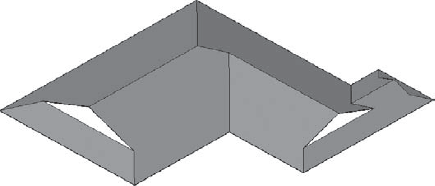
As you have seen by sketching the footprint and applying slope angles to the edges, you can create many distinctive roof shapes (see Figure 5.21).
Another method you can use to create a roof is to use the Roof by Extrusion tool. This option is a good one to use if you have a fairly straight multisloped roof system with areas that need to be cut out.
The Roof by Extrusion method uses a profile of the roof shape that you want to create, which is then extruded over the length of the new roof segment. Imagine drawing the roof shape in section first and then deciding how far forward and backward it should extend.
This tool needs a work plane. We can use a reference plane to define it. You can find it on the Work Plane panel of the Home tab. Choose the Draw Reference Plane option. In a plan view draw the reference plane (or you can use a grid line) perpendicular to the direction in which you want to extrude the roof. It is important to name the reference plane; otherwise, you won't be able to use it as the work plane for your roof sketch, and we intend to do so. You can name the reference plane in the Element Properties dialog box.
From the Create panel of the View tab, click the Section View tool to create one that is parallel to the reference plane or grid. It needs to "look at" and "see" the reference plane.
On the Ribbon click the Architect & Site tab, choose Roof, and then select Roof by Extrusion.
In the Work Plane dialog box that appears, choose the reference plane or grid you created as the work plane. If you didn't name the reference plane, it won't be listed.
The Go to View dialog box appears, suggesting that a floor plan is not the best view to use to sketch your Roof by Extrusion. The dialog box offers you some better views that are parallel to your reference plane/grid.
Select the new section view that you created and click Open View. In the Roof Reference Level and Offset dialog box select the level you want your roof to reference, and assign an offset if desired. This will create the relationship between your roof and this level.
Sketch the lines that represent the roof shape. The sketch needs to be continuous connected lines and, unlike nearly all other sketches in Revit Structure, this one does not want to be a closed boundary. The sketch you create will define the top of the roof surface.
Click Finish Roof. Select the finished roof, and then on the Element panel of the Home tab click the Properties box. Assign new values for Extrusion Start and Extrusion Finish. If the reference plane you created is the middle of the roof, then enter a positive value for one side and an equal negative value for the other side to create a roof centered on your reference. Both values should be half of your desired overall roof depth or length.
Click OK to close the Element Properties dialog box; then open the plan view in which the roof element was drawn.
Select the roof you created, and using the grips that appear at either end, stretch out the roof in either direction relative to the current reference plane or grid (see Figure 5.22) to establish the full extent of the roof. If you want, you can lock the extents at either end to grids or other important elements that might flex during the design period.
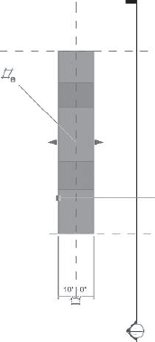
Figure 5.22. The Roof by Extrusion method: stretching the roof extents by clicking and dragging the blue triangles
After you have finished the basic Roof by Extrusion shape, you can add openings for light shafts or other purposes such as mechanical openings, as follows.
To add an opening, you create a void that cuts out a portion of the roof you just created (see Figure 5.23). To cut an opening in the roof, follow these steps:
In a plan view, select the roof element.
On the Modify Roof panel of the Modify Roofs tab, click the Vertical Opening tool. This changes the view to Sketch mode again and displays the Create Extrusion Roof Profile contextual ribbon.
Sketch the shape of the opening you desire, and then click Finish Sketch. The opening is then cut out of the roof extrusion. Keep in mind that the sketch can be entirely within the roof boundary or extend beyond the boundary. Only the portion of the sketch that cuts across the roof will alter the roof. If no part of your sketch crosses the roof at all, Revit won't complain, but you won't see any change to the roof either. This sometimes happens when users attempt to add an opening in a 3D view.
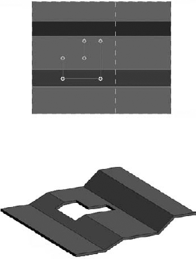
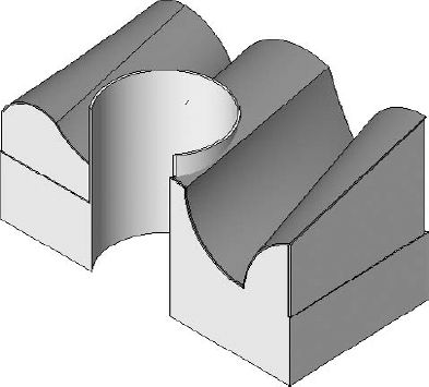
Another task you will most likely have to perform when creating the roof resembles using a cookie cutter on dough. Since the extrusion is rectangular or square, you may need to cut out a pattern from the rectangle to match your roof shape. You need to shape the edge of the rectangular extruded element to suit the shape of your structure. In this case, we are adding a void shape to cut the roof into a circular shape.
Using the same tool as before, Vertical Opening, to cut a circular shape from the rectangular roof extrusion (see Figure 5.24), sketch an inner circular boundary and then a boundary outside the overall roof extrusion. The inner circle acts as our knife edge. The outer boundary and inner boundary together define the overall vertical opening. As long as the outer boundary is larger than your roof, all of the roof outside of the circle is removed. Click Finish Roof to see the final form. Make sure that the sketch boundaries do not overlap.
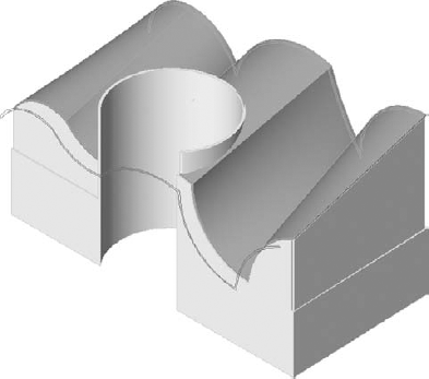
Assuming that a real project may have walls under this roof and that these walls may need to extend to the underside of this roof, Revit provides an easy way to accomplish this. Select the walls and, on the Modify Wall panel of the Modify Walls tab, click Attach. Select the roof, and the walls will automatically be attached to the underside surfaces of the roof. While the Attach tool is active, the Options bar provides the opportunity to choose whether to attach the top or bottom of the walls to a roof or floor.
Keep in mind that the Vertical Opening tool defines a plumb cut through a roof. If it is necessary to define an opening that is perpendicular to the roof surface, another tool is available. You'll need to consider using the Opening by Face tool. It can be found on the Opening panel of the Modify tab. It too is defined with a Sketch mode.
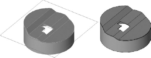
Figure 5.24. Using the Roof by Extrusion method to cut a new circular shape as well as attach walls to the underside of the roof
If you need to alter the openings you created in your Roof by Extrusion shape, select the roof and choose either Edit Profile (to change the extrusion profile/shape) or Vertical Opening (to return to Sketch mode for the opening(s)).
Next we'll look at another set of roof tools to model flat roofs that slope from ridges to drains, which are found in the majority of typical commercial buildings. If you can learn to make these types of roofs, you will be able to model most of the projects that come your way.
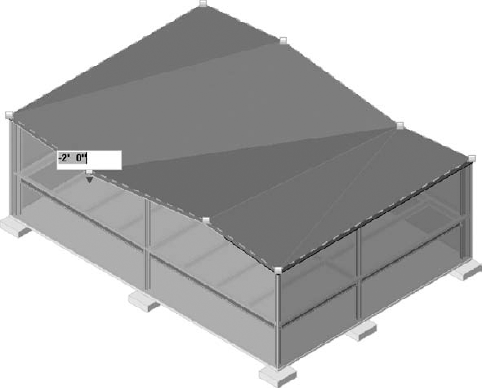
For commercial construction, many buildings will have a "flat" roof. In reality, the roof is not flat but must slope slightly in order to drain rainwater, usually at about
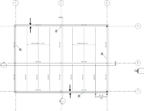
As you can see in Figure 5.25, the roof low point, where the water drains, will be located at −2′-0″. The roof ridges are at 0′ in relation to the roof level. Using the method of working with flat planes, you could try to model a series of triangular surfaces to make the whole roof, but modeling would be cumbersome and time consuming. Revit Structure uses a set of tools referred to as Shape Editing. These tools help you create this type of warped roof surface.
The general process looks like this:
Create a Roof by Footprint shape; it must not define any slope.
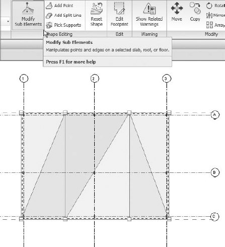
Highlight the diaphragm, and the subelements become available on the Shape Editing panel of the Modify Roofs tab on the Ribbon. The four subelements have the following properties:
The Modify Sub Elements tool (see Figure 5.26) puts you into an editing mode where you can pick the lines and points and apply an elevation value.
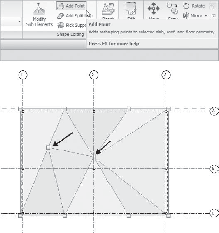
The Add Point tool lets you to add points anywhere within the roof boundary (see Figure 5.27). Once you place points, you can use the Modify Sub Elements tool to alter its elevation value relative to the level of the roof. These points can act as drain points or low points for the typical flat roof we are using as an example.
The Add Split Line tool is used to add lines to the diaphragm (see Figure 5.28). Then you can add an elevation value. These lines can act as ridge lines or valley lines on your roof.
The Pick Supports tool allows you to select supporting beam members that define how the roof should slope.
Use the Reset Shape tool to discard all of the added subelements and return the diaphragm to its original shape.

Now that you have seen the editing tools at your disposal for altering roof slopes, let's step through the process. Follow these steps to use Shape Editing to create a warped roof deck:
Create a flat roof using Roof by Footprint. Take care not to define any sketch segments that define slope. Shape Editing is not offered as an option when a roof defines slope within its sketch.
Select the roof.
Click either Add Point or Add Split Line, and place the point or line as desired.
To edit the elevations of a point or split line, do one of the following:
Select the point or split line, click on the Elevation value, and change it as required.
Dynamically alter the location of the point or split line by clicking and dragging it. You can do this in a plan or 3D view.
Keep in mind that Shape Editing is designed to do one of two things: define a roof that slopes uniformly on the bottom and top surfaces (a roof with sloping structure) or define a roof that slopes only on the surface (a roof with flat structure and built-up insulation).
For roofs that use flat structure and built-up insulation, Shape Editing is limited by the ability of the roof to permit the alteration. If you recall, earlier in this chapter we described creating a roof type. Each layer in a roof has a property called Variable. When a layer is defined as Variable, the layer can be altered using Shape Editing. Layers that are above a variable layer will also be affected by Shape Editing. This means only the bottommost layer that will need Shape Editing needs to be defined as Variable.
As a practical example, consider a roof that has a 4″ layer for rigid insulation and a thinner layer above it for the membrane. If the rigid insulation layer is variable, the Shape Editing tool will alter only the top surface of the insulation and membrane layer. Creating a negative elevation offset for a point on this roof that is greater than the thickness of the rigid insulation will generate an error message. This means you can offset an elevation only by a value that's less than the overall thickness of a layer.
When the basic roof tools are unable to deliver what you need, there is another way to make them: Model In-Place. Making more exotic freeform types of roof shapes requires that you use solid modeling techniques. The two specific solid forms we will discuss are a sweep and a blend. You access these commands on the Home tab of the Ribbon. On the Model panel choose Model In-Place from the Component drop-down.
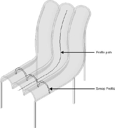
A solid sweep is useful for creating roof elements, such as canopies, that follow a varied path. Notice the sweep profile lines and the profile path line that they follow in Figure 5.29. You must understand these two concepts, profile and path, to create this type of modeled object.
A warped type of roof diaphragm often creates a smooth slope along its path (see Figure 5.30) from ridge to drain. In cases like that, the flat plane techniques that you learned earlier in this chapter will not work. An alternative is to use a solid sweep or a solid blend. Once you become accustomed to using the solid modeling features, you will be able to create nearly any shape imaginable (see Figure 5.31). You will undoubtedly face many challenging projects and some with exotic shapes. (We will cover these advanced solid modeling techniques in Chapter 19.)
An interesting approach for creating a roof diaphragm is to use a blended solid form. The use of two profiles that blend together can make difficult shapes easy to create. Using a void to cut and shape the blend, you can create many complex shapes with these tools. The basic approach is as follows:
In a plan view, create two reference planes, one at each end of the shape you wish to create. Give them the names 1 and 2.
Cut a section in front of and parallel to the first reference line; then stretch its extents past the second reference line.
Go to the section view you just created.
On the Model panel of the Home tab of the Ribbon, choose Model In-Place from the Component drop-down list.
Choose Roofs as the category, and name the new element.
On the In-Place Modeling panel click Solid and then Solid Blend from the drop-down list.
On the Work Plane panel of the Home tab of the Ribbon click Set, and select the first reference plane as the current plane.
Using the tools on the Draw panel, sketch the profile of one side of the solid (see Figure 5.32) as a closed-line sequence with the thickness of the roof.
On the Mode panel of the Create Blend Base Boundary tab, click Edit Top.
On the Home tab of the Ribbon, click Set on the Work Plane panel, and then select the second reference plane to make it current.
Draw the second profile in the same way as you did the first except for its specific profile.
On the Blend panel click Finish Blend.
On the In-Place Editor panel click Finish Model.
That completes our look at how to create and edit roof decks. As you have seen, there are many different techniques available to you; just pick the one closest to your needs.
An important feature of floors and roofs is that you can attach walls and columns to their underside. This is helpful in many cases, especially for roof conditions. A warped roof, for instance, with walls below would require editing the walls in elevation to match the roof warping. If the roof outline then changes during the design process, you would have to continually go back and fix the walls. That's the kind of busywork that you do not want to be spending your project fee fixing. You want to spend your fee concentrating on your design. You want your model to have the flexibility to adjust itself through its understanding of relationships between objects.
Column attachment to the floor or roof is also important. As you can imagine, with a warped or sloping roof your columns will each have a different elevation at their top. Calculating each of those values would be time consuming, and the editing process would be grueling. Another alternative to establishing the top of the column elevation is to go into a section view, measure the distance from the top of the column to the underside of deck, and adjust it in the Column Element Properties dialog box. That too is time consuming and fairly inaccurate.
The procedure to attach walls and columns to your roof (or floor) deck is straightforward:
In a 2D or 3D view, select a column.
On the Modify Column panel of the Modify Structural Columns tab of the Ribbon you will see Top/Base, where you can select Attach (or Detach if desired); take note of the Options bar to define how the attachment should be made.
Click on the floor or roof element to which you wish to attach the wall.
The above list describes the steps for attaching a column. The steps are the same for a wall; however, the Ribbon tab and panel names change accordingly. You won't be able to attach walls and columns at the same time because the tools will not activate if you have different categories of elements selected.
Keep in mind that walls or columns will stay attached even if the form of the roof changes, as long as the roof remains located over the wall. A warning will be displayed if the attached items can no longer be attached because of a change in the roof or floor.
An important consideration for any slab or deck is the ability to create openings and depressions. Slab openings are often shafts for elevators, for mechanical ductwork, for light wells, and for other things of that nature. Depressions are often necessary for setting tile in bathroom or kitchen areas. If you want to keep the model accurate, you must address these elements.
To create the openings, you can edit the deck in the following way:
This is the simplest method. You can also make the opening flex with the beams that support the deck around it by locking them together. Put your plan view into Medium mode temporarily and lock the opening lines to the edges of the beam flanges (see Figure 5.33). That way, if the beam sizes change, the opening will change with them.
To add building core mechanical and elevator openings, use the Shaft Opening tool to make your openings. The advantage is that the openings are automatically created in all floors and roofs that the shaft penetrates (as determined by its parameters), and the openings are consistently in the same location floor to floor (see Figure 5.34). The Shaft Opening tool also lets you add symbolic lines so that your shaft has the graphical marking you need, such as an X to indicate a mechanical shaft opening, at each and every floor as well.
Adding a shaft opening to your project is not difficult, and it works like this:
Go to a plan view.
On the Opening panel of the Modify tab of the Ribbon, click Shaft.
In the resulting Sketch mode, use Boundary Lines and the Draw tools to create the opening shape.
Click the Shaft Opening Properties icon on the Element panel to access the Element Properties dialog box.
Adjust the top and bottom constraints to set the vertical extents of the shaft.
Provide level offsets a bit below and above the roof; then exit the dialog box.
Using Symbolic Lines and the Draw tools, sketch the opening symbol or graphics if desired.
On the Shaft Opening panel click Finish Opening, and Revit Structure will create the shaft.
Another feature common to slabs that you will likely encounter is the isolated slab depression. For example, you may have thin-set tile less than an inch deep in the bathroom areas of a building (see Figure 5.35). A deeper-set tile of 3″ to 4″ is also common. How you would model these depressions depends on the type.
By creating and attaching a void extrusion to the slab or deck, you can hollow out the basic slab element. That will work fine for shallow depressions. Deeper depressions may require a lowering of the slab in that area. For that type of construction, you will need to create an opening in the slab, make a new slab element within that opening, and position it at the desired elevation.
To create a depression in a slab, do the following:
Go to a plan view of the slab.
On the Model panel of the Home tab of the Ribbon, choose Model In-Place from the Component drop-down list.
Select Floors for the category, and name the new family something descriptive like Depression First Floor. You then are placed into Sketch mode.
On the In-Place Modeling panel click Void and then Extrusion from the drop-down list.
From the Draw panel use the Drawing tools to make the boundary of the depression.
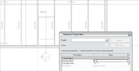
On the Element panel click Extrusion Properties.
Set the Extrusion End value at 1″ (see Figure 5.36), so that the void extrusion goes a bit above the slab.
Set the Extrusion Start value equal to the depth of the depression with a negative value.
Click Finish Model.
On the Modify tab on the Edit Geometry panel, click Cut Geometry from the Cut drop-down list.
Select the slab or deck and then select the void.
Click Finish Model on the In-Place Editor panel, and Revit Structure will create the depression.
A void blend can be used to create a tapering depression.
- Create a slab-on-grade with dropped slab edges
Using the Slab command, you can create slabs-on-grade and apply dropped edges to them with the Slab Edge function. You can also edit the profile file for slab edges in order to create new types.
- Master It
You have a new project and have to add a slab-on-grade and slab edge at the bottom level. How do you do it?
- Work with floor decks
There are different methods for creating and editing roof diaphragms within Revit Structure. Composite roofs with metal deck can be created by sketching their profile in a plan view or extruding their sectional shapes.
- Master It
Your project requires the metal deck to stop at the edge girder and the concrete to extend out one foot beyond to meet the inside face of the metal stud framing on the exterior. How do you accomplish this?
- Work with various kinds of roof decks
Different methods exist for creating roofs that are other than planar. Those methods include using the slab subelement tools as well as creating more exotic roof shapes with solid modeling tools.
Creating warped roof decks requires more complicated techniques because the form has no flat planes. Revit Structure has tools that help you create and edit the ridge lines and elevation points that occur in most roof elements.
- Master It
Your project has a main ridge line across the middle of the roof with two drains on two edges of the roof diaphragm at points that are at one-third of the edge distance. How would you create it?
- Create openings and depressions in your floors and roofs
For nearly every project you will need to create shaft and incidental openings. The dimensions of openings such as elevator shafts that extend through several floors must be kept consistent. Revit Structure has the tools to help you accomplish that goal.
- Master It
On a multistory building, you want to add shafts to the core areas for stairs and elevators. How would you do that?