
By now you are starting to get a feel for navigating the Revit Structure interface, and you are ready to delve more deeply into the techniques for modeling a structure. You have studied columns, floors, and decks, and now you will learn how to add different types of structural framing to your project.
Structural framing has many forms and materials, so you need to develop a robust set of modeling tools to create your project correctly. From the simple framing for the flat floor of an office building to a large space truss supporting an airline terminal roof, you will find many and varied conditions with which you must contend. Here you will study the methods used to frame various elevated floor and roof decks. Some of the types of roof shapes that you will learn to frame in this chapter are:
Flat diaphragms for floors
Sloped diaphragms for roof structures
Warped diaphragms for roof structures
To be able to model the framing for these structures you need many tools in your tool chest. If you were out doing carpentry, having just a hammer and a saw would not get you very far. So it is with Revit Structure. This chapter will deal with floor and roof framing as well as moment and braced frames. Of course, as someone working in the structural engineering field, you will find this information of critical importance since you are responsible for putting the "bones" in the building.
Your objective in this chapter is to learn the techniques required for adding structural framing members to your working model. When you finish this chapter, you will have a good, working knowledge of how to populate your project with various steel, concrete, or wood framing members.
In this chapter you will learn to:
Understand structural framing families and properties
Add floor framing
Add roof framing
Create moment and braced frames
Revit Structure ships with many types of framing families, each of which can be easily loaded into your project. To keep your project from getting too big and slow, you load in only those member sizes that you require for that particular project. The framing libraries encompass all those found in the AISC library, and many international libraries are included as well. You probably realize by now that Revit Structure has a truly global reach, one that works well with both metric and imperial settings. Besides the libraries that ship with Revit Structure you can create custom framing families as well either from scratch or by adapting an existing framing family to suit your needs. First, let's look at the available framing libraries, and then we'll see how to customize them.
Here is a partial list of the extensive framing families available in Revit Structure:
Concrete
Concrete: Rectangular Beam
Pan Joist
Pan Joist with Ledges
Precast: Double Tee
Precast: Hollow Core Slab
Precast: I Shaped Beam
Precast: Inverted
Precast: L Shaped Beam
Precast: Rectangular Beam
Precast: Single Tee
Precast: Solid Flat Slab
Light Gauge Steel
Light Gauge: Angles
Light Gauge: Furring Channels
Light Gauge: Furring Hat Channels
Light Gauge: Joists
Light Gauge: Runner Channels
Light Gauge: Zee
Steel
BG Joist Girder
Castellated Beam
Cellular Beam
DLH – Series Bar Joist
Double C-Channel
G Joist Girder
GP – Bearing Pile
HSS – Hollow Structural Section
HST – Round Structural Tubing
K-Series Bar Joist – Angle Web
K-Series Bar Joist – Rod Web
L-Angle
LH-Series Bar Joist
LL – Double Angle
MC – Miscellaneous Wide Flange
MT – Structural Tee
Plate
Round Bar
S – American Standard
SLH-Series Double Pitch Joist – 5 Panel
SLH-Series Double Pitch Joist – 7 Panel
SLH-Series Double Pitch Joist – 9 Panel
SLH-Series Double Pitch Joist – 11 Panel
SLH-Series Double Chord Bar Joist
ST – Structural Tee
VG – Joist Girder
WRF – Welded Reduced Flange
WT – Structural Tee
WWF – Welded Wide Flange
W – Wide Flange
Wood
As you can see, there are many types and varieties of members you can use to make your virtual model.
But what if the framing member you require for your project does not exist in the Revit libraries? When you first start modeling, you will rely heavily on the built-in libraries. If what you want is not there, you can check for families at the websites for AUGI (Autodesk Users Group International) or Revit City, where many people have uploaded their own families for others to use. If you still cannot find what you want, you will have to build your own. After you have had a chance to try it a few times you will find that the process of adapting and creating your own families is not that hard and that it is not as intimidating as it sounds.
If a member size or shape does not exist in the Revit libraries, you have several alternatives. You can create your own structural framing member from scratch using solid modeling tools, or you can adapt an existing family to fit your needs. You adapt an existing family by editing the text database, called a Type Catalog, file that is associated with it, in order to add odd member sizes or out-of-date sizes (see Figure 7.1) that might not already be there.
The text file is located in the Framing folder along with the Revit family file (with the .rfa extension). The text file has the parameters listed on the top line that describe the basic shape of the element, such as flange width (bf) and web thickness (tw) that you will have to provide in order to make your new size work.
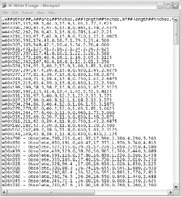
To add a new size to the existing family file, first add a description of the element, such as W12x16.5 – Obsolete. Then fill in the values that describe its shape, as in the following parameter list for a steel beam with imperial units:
W##other##
A##area##inches
d##length##inches
bf##length##inches
tw##length##inches
tf##length##inches
k##length##inches
Make sure each parameter is comma delimited (with no spaces), and follow this order exactly. So to add a new size to an existing library, simply add a new line anywhere in the text file and fill in the values you want for the various parameters that determine the size of the element. When you reload the family into your project, the new size you created will be available for placement into your project. This is one form of adaptation for an existing framing family.
Besides simply adding new sizes to your family, another example of family adaptation is one that not only changes the size but also changes the shape of the family. You will see an example of this kind of adaptation in Chapter 19, where you will add a wood nailer element to the top of a steel beam family for use in a project that has both wood and steel framing (which is a common occurrence for many commercial facilities).
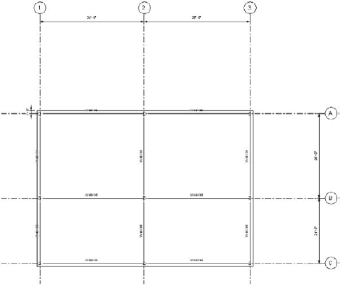
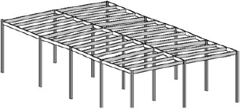
For the most part, the framing that you add to your building project, whether it is steel, concrete, or wood, will be supporting some type of elevated deck (see Figures 7.2, 7.3 and 7.4). Of course, in some projects the majority, or even all, of the framing supports piping or mechanical devices such as industrial production facilities for gas and electric plants or test frames for new aircraft.
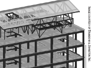
Figure 7.2. Steel-framed office structure with composite metal deck and concrete floors, a sloping roof to support Spanish tile, and mechanical equipment platforms for HVAC

Figure 7.3. Concrete parking structure with pre-stressed, post-tensioned (PT) concrete framing supporting PT decks
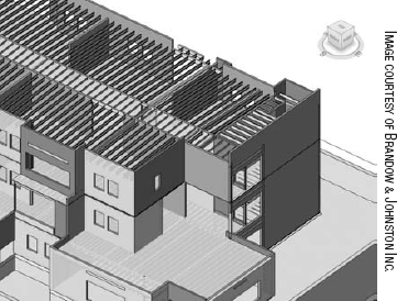
Figure 7.4. Multiple-housing structure framed with lumber connecting to wood bearing and shear walls
One important consideration when adding framing elements to your project is establishing the reference plane to which they are attached. This issue goes to the very core of Revit Structure and its constraint-based philosophy. Since you are working through an ever-changing design process, from schematics through to construction documentation, the model must always have as much flexibility as possible. You need this flexibility in your model to do such things as stretch to different-sized bay widths and adjust story-to-story heights between levels in case the design changes.
The basic vertical constraint for floor framing in your project will be the level to which the framing is attached. The basic horizontal constraints will be your grid system. Constraining your framing elements to these two datum elements will allow you to flex the model when needed as the design process continues.
The level you draw the framing on is the default for its constraint, so if the level moves, the framing will move with it. One added complication is that the framing is often below the deck, so members need to be offset downward below the deck element. You can do this by highlighting the member and changing the values for its offsets in the Instance Properties dialog box. It is easy to forget to do this, and you could end up with framing at the top of the deck unless you are paying close attention. Also, if the deck depth changes due to design updates, you have to remember to select and edit all the framing member offsets. So what is the best practice?
Many advanced users elect to use the bottom of the deck as the reference plane for attaching the framing. That way, they keep the deck constrained to the level and do not have to worry if the depth of the deck changes, because the support framing will move as well. Others create a new level or use a reference plane at the top of steel elevation so they do not have to worry about setting offsets. That seems like a better way to go. Try the different methods to determine which one works best for you.
In the next section, you will learn to create basic floor framing for an elevated deck in your virtual model. As opposed to roof framing on a sloped or warped deck, floor framing is mostly flat and fairly straightforward to model, so that is a good place for you to start in order to understand how this all works.
As we said earlier, you will learn to create your framing in a workflow that is similar to how the members would actually be constructed in the field. Assuming that the grids and levels are established in your project and that columns and decks have been created, now you will move on to adding your floor framing. So where do you begin? The columns are there already, so the first step to framing the floor will be to connect the columns with girders as you construct your virtual model. You will find the Beam command on the Structure panel of the Home tab of the Ribbon, but first it is important to understand its available options.
How do you proceed when you want to add floor framing to your project? Depending on the way you prefer to work, you can add either the floor deck element or the framing elements first. But since the framing supports the floor deck layout, it is best practice to proceed with the deck first, though it is not absolutely necessary. That way you can easily follow the shape of the floor while you add its support framing. However, for sloping or warped roof deck framing, it is essential to create the deck first for reasons that will be explained later in the chapter.
Let's look at the various options now on the Options bar and Ribbon to aid you in placing members into your model. When you start the Beam tool, found on the Home tab of the Ribbon, the Place Beam tab appears on the Ribbon and the Place Beam options are displayed on the Options bar:
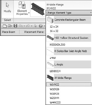
On the Element panel the Type Selector will list, in a drop-down menu, all the currently loaded beam sizes (see Figure 7.5).
Next to the Type Selector is the Element Properties icon, which you can use to set or edit the various parameters of the framing. (See the next section for a discussion of the Element properties.)
On the Detail panel is the Load Family icon, which allows you to easily load new shapes from the framing libraries that you want to use in your project.
To the left of that, on the Draw panel, are the tools that enable you to add the beam to the view by drawing or picking.
Finally, the Multiple panel has the On Grids option, which allows you to pick grid lines and is another, faster way to place your beam members.
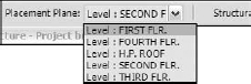
On the Options bar the Placement Plane drop-down menu (see Figure 7.6) allows you to choose the level (work plane) on which you want to add the beam element. Usually the value is set to the floor you are working on, but you can set it to another plane of your choosing.
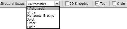
The next pull-down menu sets the Structural Usage field for the new beam (see Figure 7.7). As we discussed earlier, there are five categories you can use. If you leave the value on <Automatic>, Revit Structure makes its own judgment as to what structural usage the new element should be assigned. When this field is set to <Automatic>, Revit will assign elements like this: girders connect to columns, joists connect to girders, and purlins connect to joists. If you leave Structural Usage set to <Automatic>, you need to pay close attention because improperly connected beams, or ones where Revit gets confused (yes, Revit does get confused sometimes), will be assigned to the Other category. The Other line weight is usually set to a pen weight of 1 so that those members, when printed, will look very thin.
Some people like to set each Structural Usage type to a different line weight, with girders being the thickest, in order to distinguish among them. Others set all the lines the same weight regardless of Structural Usage assignments. It is one of those judgments that you need to make for yourself and your own firm.
You can configure each beam type with a different color for easy monitoring in the Object Styles dialog box (see Figure 7.8). For each of these beam categories, you can also independently define the line weight and line style properties, so you can make girders a heavier line weight than joists or alter the display in whatever way is required for your project.

Figure 7.8. The Object Styles dialog box lets you universally control the display of your beams and girders in their various views.
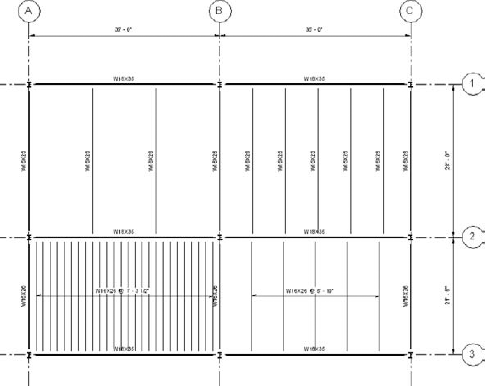
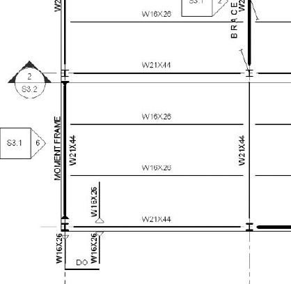
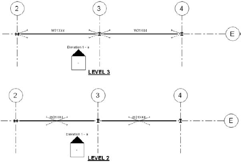
For a good example of how beam presentation can differ, see Figure 7.9. On a structural framing plan, the seismic system (the moment or braced frames) is usually displayed with the heaviest line weight, so it "jumps right out at you," so to speak. The plan view in the figure has the rigid frame member's Structural Usage parameter set to Other. The Other parameter is then set to a line weight of 7 in the Object Styles dialog box, for projected lines. The girders are set to line weight 6, and the joists are set to line weight 5.
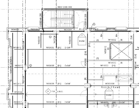
Figure 7.9. A typical floor framing plan for a steel building with differing line weights for beam elements per usage
If you are using the analytical model to export to structural analysis software, you will also want to set the Structural Usage field for the floor and roof members of the frame to Horizontal Bracing in order for it to be read correctly in the analysis software.
To the right of the Structural Usage pull-down is the 3D Snapping check box. If you select this check box, the beam will snap to the elevation of the intersecting beam or girder that supports it. This is an especially important option when you're doing roof framing. When working with sloping roof members and when framing to tops of columns that are at different elevations, you have no plane on which to place the beam. So having Revit Structure automatically find the intersecting point is critical to being able to easily and efficiently place the framing member.
To the right of that check box is the Tag check box, where you can set Revit Structure to automatically add tags to the element after placement if desired. Since tagging is displayed only in the view in which it is created, you might not want to have tags in a working view, so you can uncheck this check box before placement if you wish. Of course, concrete framing will also display well when set to a hidden view, just the way you want it to, as in Figure 7.10.
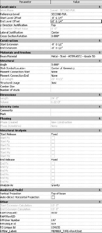
Back on the Place Beam tab of the Ribbon, next to the Type Selector, is an image of the element that Revit is ready to let you place; this could be a W-Wide Flange beam, a rectangular tube, a C- channel, and so on. To the left of the image of your selected family is the Element Properties button. When you click this button, you can set or edit the various parameters of the framing element in the resulting dialog box (see Figure 7.11). You will be constantly using this dialog box to adjust the properties of your elements. The dialog box includes the following major areas, referred to as Parameter Groups: Constraints, Construction, Materials and Finishes, Structural, Dimensions, Identity Data, Phasing, Structural Analysis, Analytical Model, and Other. Each of those categories has a set of parameters that have something in common with regard to the family. You can also open the Element Properties dialog box by selecting an existing beam, right-clicking, and selecting Element Properties at the bottom of the shortcut menu.
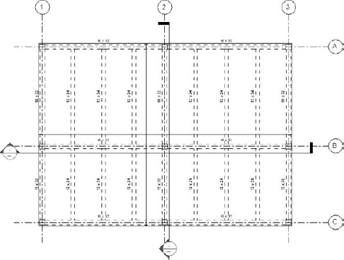
Figure 7.10. Concrete floor framing plan in a hidden mode view
You can set some of an element's Instance parameters before placing the element, which makes multiple insertions easier and more efficient. This way you do not have to repeatedly edit the element's properties after placing it in the model. Be careful when presetting the parameters, though, and remember to change them at the appropriate time.
Now that you have studied the various options for beams, their placement, and their Instance parameters, you are ready to start adding framing elements to your project. Let's begin with girder placements from column to column.
To add girders to your project one at a time, follow these steps:
Go to the view where you want to add the framing.
On the Structure tab of the Ribbon, click the Beam icon.
In the Type Selector, choose a size to add, or load one from the framing libraries.
On the Options bar, select a Structural Usage type for the beam you are adding, or leave it set to <Automatic>.
Check the Chain check box to easily create girders from column to column in a continuous pattern (or "chain").
Check the Tag check box on the Options bar to automatically add the size of the beam above the framing member once it is placed.
To place the girder, hover your cursor over a column, and then use the Tab key to cycle through the various snaps until the appropriate snapping icon appears. Use the midpoint (triangle icon) snap when possible.
Click to place one end of the girder onto the column.
In the same fashion locate the midpoint, and then click at the next column to finish placing the beam.
There are some time-saving techniques you will want to use when adding girders to your project. You can add girders by snapping from column to column individually as just described and use the Chain option for continuous placement as in step 6 above. Or you can use the On Grids tool, found on the Multiple panel, which allows you to add girders between columns automatically simply by selecting grid lines.
To place beam elements use On Grids and select the grid, following this process:
Perform steps 1 through 5 from the previous task in the same way.
Click the On Grids button on the Multiple panel.
Select a grid that has columns you want to frame between.
Revit Structure will add girders between the columns on the selected grid. The girders appear ghosted until you finish.
Hold down the Ctrl key to select multiple grids at one time.
When you have finished selecting grids, click Finish Selection on the Multiple Selection panel to complete placement.
After finishing the placement of the girders between the columns on your floor plan, you are ready to in-fill those bays with joists. After that you can add secondary framing members, such as floor openings, stair framing, and other miscellaneous framing elements, by drawing them individually. This chronology is another example of how the workflow for virtual modeling is similar to the way the building would be erected in the field.
Now that the framing bays are bounded by girders, you will use the Beam System tool, found on the Structure panel of the Home tab on the Ribbon, to add the beams that will fill the framing bays (see Figure 7.12). Beam System is a powerful and versatile tool, and one that you will use on most projects. Its benefits include its ease of use and its ability to flex when or if the framing bay dimensions change.
The basic approach to using this tool consists of the following:
There are two approaches to defining the area and direction of the beams: the one-click method and the sketch method:
- The one-click method
You simply hover your cursor over one of the girders that frame the boundary of the bay in the direction you wish the framing to be placed. You'll see a preview of the beam system in hidden line. If you don't like the orientation you see in the preview, try a girder in the other direction, and when you see the orientation you want, click to place the beam system. This method is not available in 3D views, however.
- The sketch method
You sketch lines that enclose the area of the in-fill, similar to what you've done earlier with floor sketches. This method gives you greater control over the orientation and shape of the beam system and works when the one-click method fails to satisfy.
Let's take a little closer look to learn the various options available for the Beam System command.
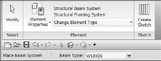
On the Element panel of the Place Beam System tab of the Ribbon (see Figure 7.13) is the Type Selector pull-down, which allows you to select different types of beam systems that you might have created. You probably will not need to use this option because only Identity data is specified in the Type parameters. To the left of that is the Element Properties icon. On the Options bar is the Beam Type pull-down, which allows you to select the beam type for the layout. Only one beam type can be called out for any one placement of the beam system, although it is possible to override one later if necessary. The Sketch panel contains the Create Sketch tool, which we will discuss in a moment.
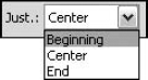
The Justification parameters on the Options bar (see Figure 7.14) control how the beams are spaced within the bay. The spacing can start from the beginning or end of the bay or be centered on the bay. It can take a moment to figure out which side is called Beginning and which is called End. The beam you select using the one-click method defines the Beginning side. It can be less obvious when you use the sketch method. You just need to examine the spacing and check the setting on the Options bar to get your bearings.
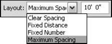
Four Layout options are available when you're placing beam elements (see Figure 7.15):
The Clear Spacing option sets the distance between members from the edge of the flange to the edge of the adjoining flange rather than at the centerline of the elements.
The Fixed Distance and Fixed Number options do just what you'd expect from their names. Fixed Distance sets a specific distance between beam members even if the framing bay changes shape. Fixed Number sets a specific number of beams in the framing bay regardless of the spacing between members.
The Maximum Spacing option in-fills the beams using the value in the box to the right of the Layout box. This is the most powerful option because it remains dynamic if the bay dimensions change. Over the course of the project, if the bay expands enough so that the members exceed the Maximum Spacing value, then new members will automatically be added into the bay. If the bay gets smaller, members will be eliminated. This helps you achieve your goal of making the model as flexible as possible during the design process.
Checking the 3D option helps you define a sloping beam system, which is needed, for example, when the member it intersects is sloping (see Figures 7.16 and 7.17 for a comparison). You will be hearing a lot about this important option later on in the chapter when we discuss roof framing.
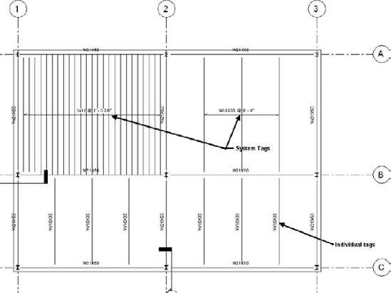
The Tag option (see Figure 7.18), if checked, will enable two types of beam tags: System (beam system tag) or Framing (individual beam tags). The System type is best used for framing, such as for wood-framed floors with many members where spacing is very tight. If you tried to tag each one of those elements, it probably would look too crowded on your plan.
As mentioned earlier in this section, there are two methods of placement: one-click and sketch. The one-click method is easy to use (see Figure 7.19). You simply hover your cursor over an existing girder that bounds the area you are in-filling and one that is in the direction you want the framing to be added. The framing then will ghost in with blue dashed lines until you click for final placement. You will find that this method allows you to complete a whole floor of framing on your model in minutes. It is so easy that sometimes it is faster to erase the framing and redo it if design changes warrant it. Remember, though, that the one-click method is not available as an option unless you have a bay completely enclosed with beam elements.
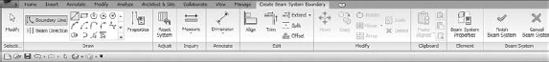
In some cases, the one-click method does not work, and so you must use the sketch method. First, click the Create Sketch icon on the Sketch panel of the Place Beam System tab. The Create Beam System Boundary tab is then displayed on the Ribbon (see Figure 7.20). By using the tools in the Draw panel you can sketch the lines that define the shape you require for that bay (see Figure 7.21). Or you can use the Pick Supports option to select the supporting elements that form the boundary of the framing bay.
An important option in this menu is the Reset System function. If after placement your design criteria have changed and you must respace the elements in the bay, you will find that sometimes the display does not update correctly to the new bay shape and still displays the stick symbols as they were, without showing the new spacing or span direction. This is especially true when you're expanding a bay. The members might not display to the new extents. In that case, you need to use this option to make the display update correctly.
So that explains the various properties and options available for you to use in the placement of beams in your project. Next you will take a look at how to add curved beam framing to your model.
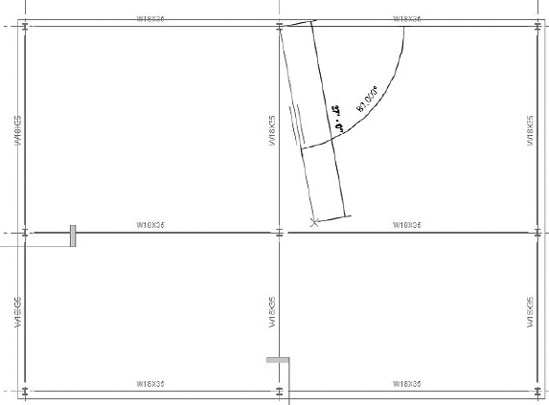
Almost every building project has a curved beam or two (see Figure 7.22), so it is very important to be able to easily create them in your model. For example, you might need one in order to create support for a barrel-style roof or for supporting an exterior curved edge of a deck. You create curved beams by using the drawing tools on the Draw panel of the Place Beam tab. You can draw such shapes as an arc, circle, or spline as a path for the beam shape. You can also create curved beams by picking a curved line on your plan.
To create a curved beam on your floor plan, do the following:
On the Place Beam tab, click Change Element Type, and choose the beam type from the drop-down list.
On the Draw panel, pick one of the drawing tools, such as Start-End-Radius Arc, Center-ends-Arc, Spline, or Tangent-End-Arc, and draw the centerline of the member on the plan. Or you can click the Pick button and select a line already present in your project, and Revit will place a curved beam to follow it.
You might have wondered in Chapter 5 why we didn't discuss concrete pan joist systems (waffle slabs) or precast slab systems. The reason is that these subjects are better dealt with here, since the concrete slab and concrete framing are monolithically constructed. As opposed to the approach we took for steel and concrete beams, these systems load in as units for specific layouts.
- Pan joist supported slabs
A pan joist system (often called a waffle slab) can be easily constructed by using the Pan Joist concrete framing family. You create these by placing a beam system layout in each direction in the same bay (see Figure 7.23). The two beam system placements will "clean up" and display monolithically.
- Precast supported slabs
Precast-Hollow-Core Slabs, Single, and Double-T system families are all available in the Revit Structure concrete framing library (see Figure 7.24). Individual panels are created to specific widths and then arrayed across the area of the floor. The framing libraries contain the basic framing shapes you will need for precast framing, with Precast Inverted-T girders, L-Shaped girders, and more.
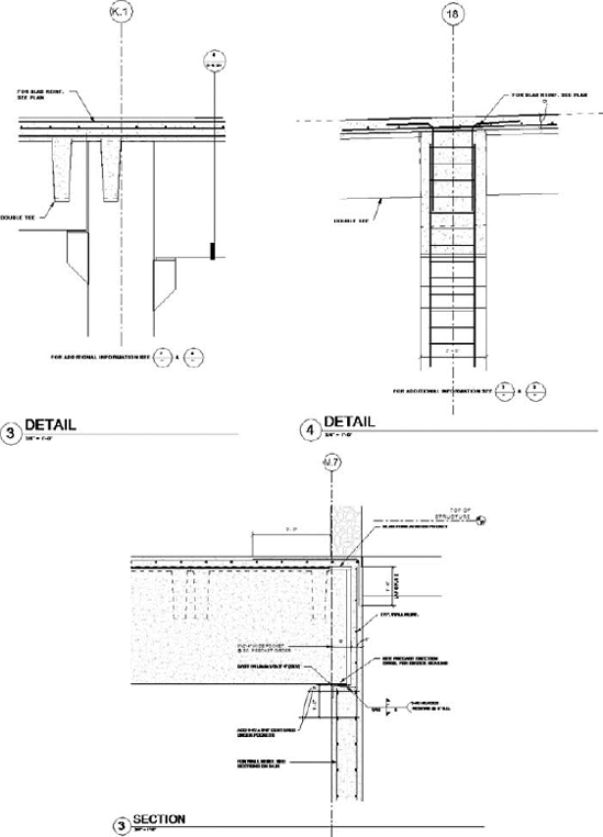
Figure 7.25 shows some sections that have been cut from a precast structure. 2D annotation is added, as well as reinforcing. The reinforcing can be added either as a 3D component of the element or as 2D drafting detail lines.
- Pre-stressed post-tensioned (PT) framed concrete structures
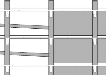
Concrete structures using PT (pre-stressed and post-tensioned) systems are quite common and can be readily modeled in Revit Structure (see Figure 7.26). PT beams are nonrectangular, so you can use the Pan Joist family or adapt your own family depending on how accurate you want the beam to appear.
It is important for you to develop good judgment about the extent to which you add detail in your model families. Adding in a 1″ chamfer to the concrete beam interface with the slab might be accurate, but it might be unnecessary if you do not intend to use views in your construction documents for a lot of detailing.
In the next exercise, you will practice placing in-fill beams into a project using various methods of placement.
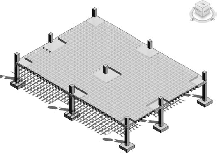
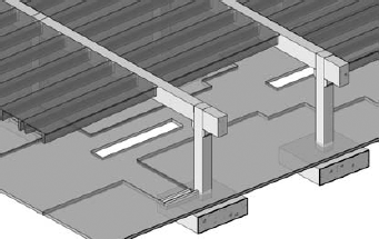
Figure 7.24. Many framing types are available in Revit Structure, like this precast concrete system.
Exercise: Adding Girders to a Floor Plan
This exercise will have you add girders first and then in-fill beams on several bays in a simple steel structure. You'd use the same procedure for concrete or wood framing members.
First, you'll place the girders individually and then by using the On Grids method:
Open
Dataset_0701_begin, where you should see a grid and steel columns in the view Structural Plans – Level 2.On the Structure panel of the Home tab on the Ribbon, click Beam.
Select a W18x35 beam type in the Change Element Type drop-down list.
On the Options bar, select Girder in the Structural Usage field, and enable the Chain check box.
Hover your cursor over the column at grid A1 until a magenta (pink) triangle snap appears; then click to place one end of the girder. (If necessary, use the Tab key to cycle through snaps until you get the middle snap.)
Move your cursor down to hover over the column at B1 and click, and then click again at C1 to finish placing two beams across grid 1.
On the Multiple panel on the Place Beam tab, click the On Grids tool.
While holding down the Ctrl key, select grids 2 and 3. The beams should appear ghosted in.
Click Finish Selection on the Ribbon to complete the operation.
On the Multiple panel on the Place Beam tab, click the On Grids button again.
Holding down the Ctrl key, select grids A, B, and C; then click Finish to complete the placement. Your plan should look like the following illustration.
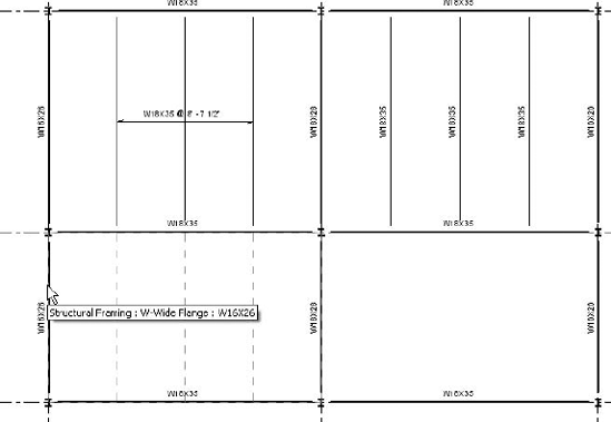
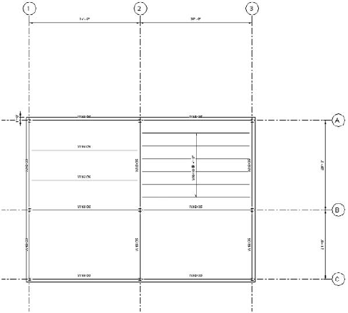
Now that the girders bounding the bays are complete, you will in-fill the four bays using the Beam System tool:
On the Structure panel of the Home tab on the Ribbon, click Beam System.
On the Options bar select W16x26 from the Beam Type drop-down list.
On the Options bar select Fixed Number in the Layout Rule drop-down list, and type 2 in the box next to it.
On the Options bar click Framing for the tag type.
With your mouse hover over the girder that runs from A1 to A2 (you should see two dashed blue lines parallel to the girder in the bay on the left).
Click the girder (A1 to A2) to finish placement in that bay.
Change the Beam Type to W8X10, change the Layout Rule to Maximum Spacing, and type 48″ in the box next to it.
On the Options bar, this time change the tag type to System.
With your mouse hover over the girder that runs from A2 to A3.
Click on that girder to create a beam system in that bay. Your plan should now look like the following illustration.
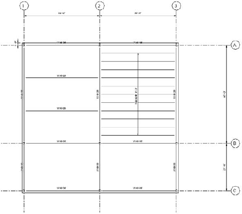
Now let's flex the bay by changing the grid spacing to see how the beam system reacts:
Select grid A and then click on the temporary dimension value between grid A and grid B.
Change it to 45′−0″. (Click Activate Dimensions on the Options bar if no temporary dimension appears, and edit the Permanent Dimension value in the view instead.)
Notice in the following graphic that when the bay stretches, members are added to the bay with the Maximum Spacing layout rule, whereas the bay with the Fixed Number layout rule simply respaces the two members. I added a dimension so it flexes now.
Click Beam System again on the Home tab of the Ribbon.
Click the Create Sketch icon on the Sketch panel.
On the Draw panel click the Rectangle icon.
Draw a rectangle from grid B1 to grid C2, and as before take care to snap to the midpoint of the columns; then lock each line into place by clicking on each open lock symbol.
On the Draw panel on the Ribbon click the Beam Direction tab and then select the girder that runs from B1 to C1.
On the Element panel click the Beam System Properties icon to access the dialog box.
Set Layout Rule to Fixed Distance, and set the value to 8′-0″ in the Fixed Distance box.
Set Justification to Beginning and Beam Type to W14x30.
Click OK to exit the dialog box, and click Finish Beam System on the Ribbon to complete the placement. Note that the Beginning side is the left side of the bay, the first 8′ bay between framing.
In-fill the final bay with any one of the methods that you just tried.
That was not so difficult, was it? Now go to a 3D view of the model and check out the finished product.
Now that you have learned how basic floor framing works, the next task is roof framing. The roof framing tools in Revit Structure are quite similar to those for floor framing. You use the Beam and the Beam System commands just as you did with floor framing. The big difference is that you have to slope the framing elements to fit the roof deck slope. As you saw in Chapter 5, you can have many varieties of straight or warped sloping decks in your projects.
So let's see how to approach and master this process by starting with a simple sloped flat roof and adding steel framing to it. First you will learn how to attach framing to the underside of a roof. Then you will move on to frame more complicated roof shapes that slope from ridgelines to drain points.
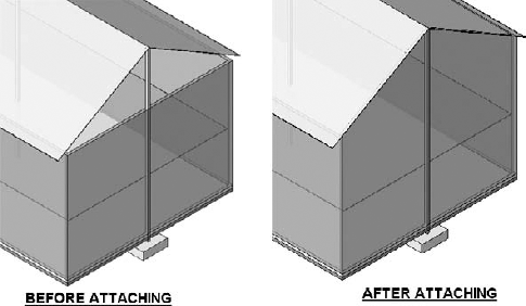
The first thing to do to prepare for adding the roof framing on a flat sloped roof of this type is to extend the walls and columns to the underside of the roof deck, which we discussed in Chapter 5. To attach the walls and columns, highlight them in a 3D view, click Attach on the Options bar, and then select the roof deck element where you want them attached (see Figure 7.27).
If the roof segment is a straight sloping plane, you can attach your framing to it with this technique. Using the methods you learned in Chapter 5, create a flat sloping roof deck in a new file. The general method for adding your framing is as follows:
Go to a section view of the roof deck.
On the Home tab of the Ribbon, click Set in the Work Plane panel.
In the Work Plane dialog box, select the Pick a Plane option, and then click OK.
Click the underside of the roof deck. (You may need to activate Thin Line display to make it easier for you to see the roof surface lines in section.)
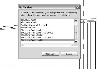
The Go to View dialog box will appear, prompting you to choose a better view to display—that is, where you will draw the members in plan (see Figure 7.28). You must go directly to that view or the work plane will not be established.
In plan view, you draw the members just as you did the floor members, and they will attach to the underside of the deck. The advantage of this approach is that if you need to edit the slope of the roof diaphragm during the design process, increasing or decreasing it, the attached roof framing will move with it, thus avoiding a lengthy editing process.
What about the analytical model lines? Their locations can be independently located by setting the Vertical Projection parameter of the element. See Chapter 15 for a more complete description of how the analytical lines can be adjusted.
Now you have a grasp of the basics of sloped roof framing. The material can be wood, concrete, or steel, but the modeling principles are the same. This type of modeling will work for many of the conditions that might arise. But what about those conditions where the roof varies and is not on one plane? In such cases there is no consistent flat plane where you can attach the framing. In the next section, you will learn how to work with those types of conditions.
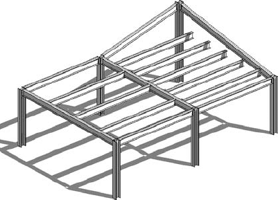
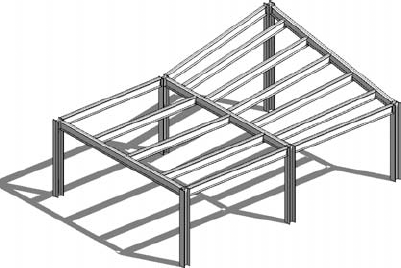
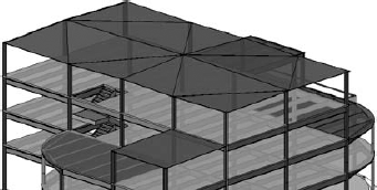
It is common in building design for roofs to slope from ridges to drains in order to drain rainwater, creating a roof that warps and has no consistent flat plane (see Figure 7.29), as you saw in Chapter 5. Even if this is the case, there is a method of basic straight-line generation that will allow the warped surface to be framed using straight beam elements. In this section, you will learn how to model a roof of this type.
This next example will use a deck that slopes about
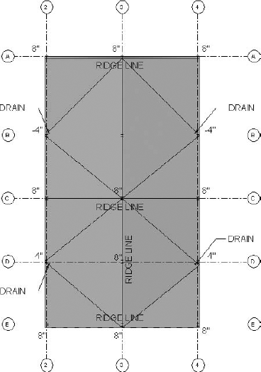
In Figure 7.30, you can see that the ridgelines in this example are 8″ above the roof line datum. The drain points are −4″ below the roof line datum. (The slope values are exaggerated to make them easier to see.) The rectangular area between grids 2C and 3E has ridges on three sides; then the surface slopes down on the fourth side to the drain location. When you frame that bay, the end of each beam will have a different elevation.
Before you see how the bay is framed, you need to learn about 3D snapping. The next section will give you the essentials.
One of the most important concepts to discuss for sloping members is 3D snapping (no, that is not something you do to the person in the next cubicle with an elastic band). When you did the floor framing, you were able to set the members at one elevation, easily specified and controlled, with each end at the same elevation relative to the floor level or reference plane. But for a warped roof system with drains and ridges, every beam is sloping, so establishing and then editing the tops of steel can be very tedious. What tool does Revit Structure offer to help you handle this condition?
It's handled with the 3D Snapping option. When you choose the Beam or Beam System command, the 3D Snapping option will appear on the Options bar as a check box. Check it as you are creating sloping members, and they will snap to the top of column, or to the intersecting sloping girder, or to a wall. That way, you do not need to compute the elevation yourself (which would take way too much time).
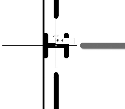
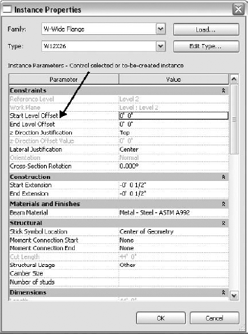
Once you place the beam elements, you can also edit their Start and End elevations. When you select the member, the elevations at each end will be displayed (see Figure 7.31). Click the elevation value, and you will be able to change it. You can also modify their value(s) using the Instance Properties dialog box by setting the Start and/or End Level Offset parameters (see Figure 7.32).
These work fine when you want to edit individual conditions, but you would not want to do that for an entire roof system. 3D snapping offers a more automated approach to creating all the necessary sloping members.
Note that 3D snapping does not work with the Grid option or with the Chain option on the Options bar.
Now that you understand how 3D snapping works, you can proceed to add the framing to your roof element. Here's how it is done. After you have placed columns and attached their tops to the underside of the roof deck, you can add the girders by snapping from column top to column top. They will be placed at the underside of the deck right where you want them without you having to compute anything. Then the framing bays are in-filled using the Beam System command, but with the 3D Snapping option checked. That way each beam will automatically snap to the elevation of the sloping girder to which it is attached, again with no need to compute any top-of-steel elevation. Furthermore, if you edit the elevation of the sloping girder, the in-fill beams will automatically flex to the new elevation.
Unfortunately, if you edit the top of the column elevation, the girder will not stay attached to the top of the column. This means that you will have to go column-by-column in a plan view and manually adjust the girders to their new position or redo the framing entirely. If only Autodesk would resolve this issue, the whole roof framing system would flex automatically when the warped diaphragm shape changes.
The next exercise will lead you step-by-step through the techniques for adding framing to a warped roof diaphragm.
Exercise: Adding Roof Framing for a Warped Roof
First, we'll attach the columns and walls to the roof diaphragm:
Open
Dataset_0702_begin.Select everything, and then on the Multi-Select tab on the Ribbon, click the Filter icon on the Filter panel.
Leave only the Structural Column category checked, and then click OK.
On the Ribbon on the Modify Structural Columns tab, click the Attach icon on the Modify Columns panel, and then select the roof.
You will get a warning that you are attaching to a nonstructural object, but that is okay. The columns will stay attached unless you detach them, even if the shape of the deck changes. Of course, now each column top is at a different elevation on the sloping surface, which is difficult to calculate manually but is exactly the way we want it. Next, let's add girders between the columns:
In the Project Browser, double-click the Level 3 plan view.
On the Ribbon on the Manage tab

In the Snaps dialog box, uncheck all but the Points snap, and then click OK to exit.
Click the Beam icon on the Home tab of the Ribbon, and then select a W16x26 size from the Type Selector.
Hover your cursor over a column top to activate the Points snap.
Click to place one end of the beam at the column located at 2A; then click to place the other end at column 2B.
Keep adding girders until all the columns are connected. The girders all slope from column top to column top. Remember that the Chain option is ignored while the 3D Snap option is active. Check your work in the 3D view.
Next, you will in-fill the bays with sloping beam systems:
On the Structure panel of the Home tab on the Ribbon, click the Beam System icon.
On the Options bar, check the 3D Snapping check box.
On the Options bar, set an 8′-0″ Maximum Spacing as a layout rule.
Change the Tag type to Framing.
Hover your cursor over the horizontal girder in one of the bays to set the framing direction, and then click to place the beam (the one-click method).
Populate the other framing bays in a similar fashion.
When you finish, your framing should look like the following illustration in a 3D view:
When you want to make larger-scale sections of sloping members, you will find that the ends of the beams needs to be cut vertically in order for them to appear correctly in your view, as the next section will demonstrate.
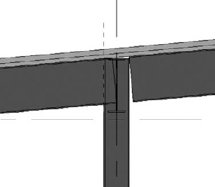
Look at Figure 7.33 and notice that the ends of the sloping girders are not cut vertically as you would need for connecting the shear plate to the column. This is an important consideration for you when you are trying to detail the connection in a section.
To correct the display, you have to create a reference plane at the edge of the column flange to cut the beam vertically:
Highlight the girder, click on the blue triangle shape handle, and then drag the end of the girder over the column flange. (This will not affect the end node location of the girder.)
On the Modify tab of the Ribbon on the Edit Geometry panel, click Cut Geometry on the Cut drop-down list. Then select the girder and reference plane (see Figure 7.34). That will do it.

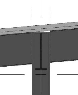
The final display will look like Figure 7.35. Also notice that the column and girder do not fully intersect with the roof. This is fine; it's how it would be constructed in reality. The framing members should be vertical and will have bent plates attached to the top flange to connect to the sloping surface of the roof deck.
Now that you have added your floor and roof framing, you will start work on your moment or braced frames, depending on which system your project is using. These frames will accommodate the seismic system you might be using on a steel or concrete building, depending on where your building will be located in terms of seismic zones.
When you model moment frames, you use standard framing techniques as described earlier in this chapter, but you must adjust the display to add Moment Connection End symbols on the ends of the frame members. You might also want to display the moment frame girders with a heavier line weight, which you can do by assigning them to a particular structural category or through use of a filter.
One way to show the frame members with a heavier line weight is to assign the moment frame members to the Other category for that use, as was described earlier. Another way is to build a filter, which is used in conjunction with Visibility/Graphic overrides in views. Filters are very powerful. After you place the frame member, you should put an entry such as MF in the Comments parameter. That will identify that instance as a frame member for which you can then create a filter. In a given view, using Visibility/Graphic overrides, you can use the filter to display the member with a heavy line weight.
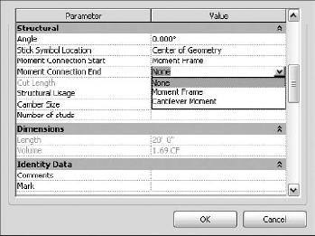
Though not moment frame items, cantilevered beams that are moment connected need a similar symbol, an open triangle, added to one end of the element. The symbol works just like the Moment Frame symbol. Unfortunately, it isn't obvious enough, so it can be annoying to figure out which end to select in the Element Instance Properties dialog box. The parameters Moment Connection Start and Moment Connection End are related to how you placed the member, but who remembers that when you come back to add the symbol? It is best add the symbol right after placing the member because the point you place first is the Start; otherwise, it becomes guesswork.
To add a Moment Frame or Cantilever Moment symbol, highlight the member and click Instance Properties from the Element Properties drop-down list on the Modify Structural Framing tab of the Ribbon. In the Instance Parameter area of the resulting dialog box, set the Moment Connection Start and/or End value to Moment Frame or Cantilever Moment, which will add the corresponding symbol to the end of your beam (see Figure 7.36).
One factor you should consider when displaying the symbols is the distance of the symbol from the column in your Coarse mode plan view. If it appears too far from the column or overlaps the column, you can adjust the distance. Choose Structural Settings on the Manage tab of the Ribbon, and change the Symbolic Cutback distance for Beam/Truss to a value that displays well on your plan view. Be careful, though, because this will change the end distances for all your beams in the project throughout all views. A possible way around this would be to go into the tag family itself and adjust the symbol location.
In the Structural Settings dialog box you set the default values that control the display of Brace and Moment Frame symbols (see Figure 7.37). If the symbols do not correspond to your company standards, you can change the default version of the symbol or make your own. You assign your own symbol in the Structural Settings dialog box for the entire project.
A common display problem you will likely encounter is that the cantilever open triangle can appear too thin in plan view, and it can be quite frustrating trying to find out where to adjust its line weight. To adjust the open triangle line weight, click Settings on the Manage tab, and on the drop-down list click Object Styles
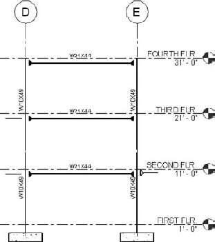
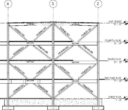
Projects using steel moment and braced frames usually require the creation of frame elevations. This is an important consideration on any project, and Revit Structure has the special Framing Elevation option to make the process easier. The Framing Elevation command is found on the View tab of the Ribbon on the Elevation drop-down list of the Create panel. It creates an elevation of the frame and is attached to a grid line. Figure 7.38 shows a typical moment frame displayed using Detail Level: Coarse, where the frame members are displayed as stick symbols. The floor and roof categories have been shut off in this view so that only the frame shows but the foundations remain. You could also display the moment frame using Detail Level: Medium, which displays the steel members showing their real shape and size and with floors and roofs turned on for a more realistic view. But Detail Level: Medium might not be the best option because you don't see the moment connection symbols since they are designed to appear only when using Detail Level: Coarse, which means the frame members are not as easily identified.
That covers the basics for creating moment frames and cantilevered framing in your virtual building. Next, you will examine the process for creating braced frames, which involves much more elaborate modeling techniques.
Real World Scenario: Contending with Many Types of Framing
You may have been to some of those sales presentations where framing is quickly and easily added, every condition is covered, and everybody is really happy. Well, in real projects it just ain't so! A typical structural project will most likely have all sorts of odd framing conditions that fit no pattern and many types of different framing to place as well as many structural systems that need to be modeled. You will find that the 80-20 rule governs. Eighty percent of the framing goes in quickly and easily, but the other 20 percent is a more difficult case and creating it can cause lots of frustration. Your project fee will be spent in a corresponding fashion. As an example, let's consider a real project. For a moment turn to the Color Gallery in the middle of the book and take a look at the images of the Los Angeles Unified School District Central High School 16.
This recent project is a new high school campus in California. The campus has two large multilevel classrooms. The classroom floors are composite metal deck and concrete, with steel framing members and wide flange steel columns. The seismic system consists of steel-braced frames. The roofs slope at
The gymnasium structure has large steel trusses supporting the roof. The library/administration building is a two-story braced frame structure using HSS tube columns. A long canopy snakes through the campus. A subterranean parking garage is constructed with a precast concrete double-T roof that has basketball courts on top. A one-story cafeteria structure with very complicated canopies completes the campus buildings.
You will encounter numerous types of framing on your projects, and it can get quite complicated. You need lots of tools in your Revit tool chest to get it done, as well as a good deal of imagination. But once you get familiar with Revit Structure, you will find that you can accomplish most any condition you encounter.
Once the floor and roof framing is completed, you are ready to add vertical braced frames (see Figure 7.39) to your model. As stated earlier in the chapter, if you are using the analytical model, you will also want to set Structural Usage for the floor members of the frame to Horizontal Bracing.
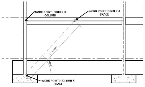
Braced frames need to be sketched in an elevation view. Usually that will be a frame elevation, as discussed earlier. The most important point to understand is that the diagonal members need to be connected to work points. A work point is usually at the center of the member that it intersects, such as a girder. As you place the diagonal member, you will see Revit trying to snap to those points. Pay close attention! Many times it will try to snap to the adjacent member, so you need to be careful. One option is to use Temporary Hide/Isolate to hide the adjacent members temporarily so it is easier to establish the correct work points.
The following exercise will lead you through the construction of a braced frame so you can see how the process works.
Exercise: Creating a Steel-Braced Frame
In this exercise, you will add an x-braced frame to a project.
Open
Dataset_0703_begin. Level 1 plan view should be active.Click the Framing Elevation command on the Elevation drop-down list of the Create panel on the View tab of the Ribbon. Note that on the Options bar, the check box for Attach to Grid is checked.
Hover your cursor slightly below grid E, and then click to select the direction of the elevation so it is facing upward on the screen.
Open that elevation; then on the View Control bar, change Detail Level to Medium.
Select the crop boundary and use its shape handles on the vertical sides to extend the boundary outside the ends of the frame on each side, making the view of the model wide enough for you to clearly see the columns.
On the Structure panel of the Home tab, click the Brace icon.
In the Type Selector, select HSSS6X6X.500 as the diagonal brace member, and be sure to uncheck 3D Snapping.
Hover over the base of a column, and click on the middle bottom of the column (if snaps are turned off from the previous exercise, turn them all back on).
Hover over the middle of the second floor beam at its center until you can snap to the work point, as shown here:
Repeat the sequence until the x-frame is completed.
Where the ends of the diagonal braces overlap the floor beams, highlight each one, and then click and drag the triangle to move the end of the brace until it clears the beam.
In the Project Browser activate Level 3 plan view.
On the Manage tab of the Ribbon click Structural Settings.
Change the Brace Symbol plan representation to Line with Angle, and then exit.
The brace symbols will automatically appear in plan views after you place the brace in elevation. Revit has two types of brace symbols in plan views: Line with Angle or Parallel Line. The Line with Angle option shows more information about the braced frame; in your plan views, it shows the start point of the brace and the direction it is going, up or down, as shown in the following illustration:

It can be important to know how the frame members are located in case there are door or window interferences on the architectural side of the design. Line with Angle, as opposed to the simple Parallel Line type, allows the architect to easily see the directions of the braces without referring to the frame elevation. You can make it even more descriptive by adapting the Line with Angle so it has a solid brace symbol, which indicates it is going up, while a dashed symbol indicates the brace is going down. Unfortunately, Revit Structure does not ship with a dashed line symbol for braces going downward. The default symbol is shown dashed in both directions. So let's see how we can create one by editing the default brace symbol. The procedure for doing that is as follows:
On the Application menu click Open
On the Create tab click Line, and then add a series of short lines in a dashed pattern to replace the continuous line.
Erase the continuous line.
On the Application menu click Save As
Back in
Dataset 0703_begin, on the Manage tab click Structural Settings.Change the Show Brace Symbol Below setting to Connection-Brace-Angle_Down, and then click OK to finish.
On the Manage tab click Object Styles on the drop-down list.
On the Annotation Objects tab change Line Pattern for the Brace in Plan View Symbols category to Solid, and then exit.
Your plan views should now look like the following graphic:
You might also wonder about the braced connection gusset plates. They are not shown unless you add them. The decision as to whether you show them in your elevation has to be a judgment call for you to make for your firm. Whereas it is best practice to show the moment frames in Coarse mode in order to see the moment connection symbols, it is best practice to show the braced frames in Medium mode. That is because braced frames are much more likely to interfere with the architecture. The frame gusset plates can sometimes get very big and might also interfere with adjacent windows or doors, so in those cases it might be a good idea to model them.
That ends our discussion about framing in Revit Structure. You have gotten a thorough overview of the capabilities and even some of the frustrations that you may encounter as you design your project. But don't be intimidated. Revit Structure is a great program and quite intuitive. If you keep adding tools to your Revit tool chest, before you know it, you will be a master.
- Understand structural framing families and properties
Revit Structure modeling is a constraint-based system that allows the model to update as changes occur, keeping the overall relationships between elements the same.
- Master It
Describe the two primary modeling constraints for attaching beams and braces, and explain why they are important.
- Add floor framing
When you add floor framing to your project, you probably start with a fuzzy idea of the size and initially use a placeholder. As the design progresses and comes into sharper detail, you will update the size and spacing in many cases. The model must have a maximum of flexibility to make the editing practical.
- Master It
You are in schematics and know the bay widths on your building will change considerably. You want your framing members in each bay to be about 10′ from center to center no matter how wide the bay becomes during the course of the design. What layout rule is the best to use in this case?
- Add roof framing
Roof framing must support roofs that slope from ridges to drains. That means all the support beams and girders must slope as well. During the design process the roof can change in shape and slope. Be aware that costly editing can eat away your at your design fee.
- Master It
Calculating the end elevation for each sloping beam would be very time consuming and a nightmare to edit. What process do you use to most efficiently place the roof support system?
- Create moment and braced frames
Moment and braced frames are an important element of many structural designs. Revit Structure has two methods of displaying the braces in a plan views: Parallel Line and Line with Angle. The symbols are placed automatically in plan view as you draw the braces in elevation view.
- Master It
Which display type is the most informative of the braced frame layouts, and how do you set it to display correctly in plan view?