
Few structural engineering firms can afford to make a three-dimensional model for its own sake. One of the main and most important strengths of Revit Structure involves its ability to create construction documents in addition to the 3D physical and analytical models. Not all modeling software can do that. In this chapter, you will focus on those documentation features and the challenge that lies in store for you as you advance your model through the design process toward completion of your construction documents.
This chapter on documentation features in Revit Structure centers on datum, annotation, and detailing functions that are found mostly on the Home and Annotate tabs of the Ribbon. You will examine the methods necessary to annotate your view, whether it is a plan, section, elevation, or other view type, in order to complete the necessary documentation for your project. Another important topic covered in this chapter is the creation and use of a typical details library, which undoubtedly will become an essential tool for you as you generate drafting views on multiple jobs.
In this chapter you will learn to:
Add datum elements to your detail and section views
Add annotation elements such as text, tags, and symbols
Add detailing elements such as detailing lines and filled regions
Create a typical details library
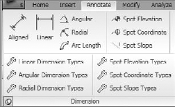
Many of the features you need to finish your details that have been cut from the model, or developed as simple two-dimensional drafting views independent of the model, will be found on the Annotate tab of the Ribbon (see Figure 9.1). The tab contains several panel groups of related drafting commands:

In this chapter you will learn how to take an undocumented view and complete it for your construction document set. It is important to remember that, like model elements, these elements are also families that can act parametrically. For example, the text family can have many types, such as a 3/32″ Arial or 1/4″ Times New Roman. Once you start developing these text types that correspond to the styles your company uses, you can add them to your project template file. Then when you begin a new project, the types will be ready to go.
Datum elements aid in the precise location of elements in your model. For a structural project, it is imperative to have well-dimensioned drawings with all major elements properly located as well as an organized grid system. The next section is an overview of the various datum elements and how they aid in the documentation of your project.
The Dimension commands are located on the Dimension panel on the Annotate tab of the Ribbon. Clicking the panel label will display a drop-down with various dimension formatting options (see Figure 9.2). Once you choose the type of dimension you want, such as Aligned or Angular, the Place Dimensions tab is displayed. The Options bar will display other tools for you to use to aid in their placement (see Figure 9.2).
On the Place Dimensions tab on the Element panel in the Type Selector are different family types of dimension styles for you to use, or you can create your own new types corresponding to your needs. If you click the Element Properties button to the left of the Type Selector, you can then choose to open either the Instance or Type Properties dialog box. There you create or edit the graphical elements of the dimension styles, as well as the lines and tick or arrow marks. In addition to formatting, you can style the dimension text.
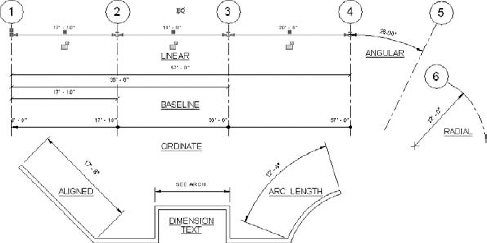
There are five basic forms of dimensions that you can use:
Figure 9.3 shows examples of these various dimension types that you can use in your project. Dimension styles can be created as baseline, linear, or ordinate styles. Notice that arrows, tick marks, and dots (as well as other symbols not shown) can be configured as dimension end point symbols depending on your preference.
The following sections will familiarize you with the usage of dimensions, how they function, how they are placed, and how the dimension text string can be adapted to show a note instead of the dimension value.
You have been learning that Revit Structure is a constraints-based system in which relationships between elements are maintained as the model flexes to new positions during the design process. Dimensions are one of the main ways to control this movement. In Figure 9.3 the linear dimension is highlighted and two noteworthy controls are displayed. Under the linear dimension line are locks that are currently open. By clicking the locks closed, you will prevent that dimension from being changed. Above the linear dimension line, the EQ control is displayed. If you click the EQ symbol, the dimensions will be equalized and each will display an EQ value in the dimension string. This is a helpful command that allows you to easily equalize the relative locations of elements.
Dimension anchors, represented by an anchor symbol at the start of an equalized dimension string, are used in a multisegmented EQ-constrained dimension to indicate which elements remain stationary when the elements change location.
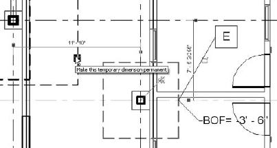
As you place and locate your model elements, you will be using dimensions long before you need them for your documentation. As you place elements in your model, temporary dimensions begin appearing dynamically as you are working (see Figure 9.4) to help you place the element precisely. By clicking on the dimension control symbol next to the dimension, you can automatically add the dimension to your view and make it permanent.
Another important concept is what is known as listening dimensions. As you start to add an element to your view, such as a line or an arc, after the initial click to place it, simply type in the value for the length you want in the temporary dimension that appears in order to place the second point.
Placing dimensions is as easy as clicking on successive elements in the view such as grids or beams or other elements. There are also several options for you to use for dimensioning to or from walls. When you start any but the Linear type of dimension command on the Options bar, you will find options that will allow you to dimension to wall location lines, such as the center of wall cores, or to wall faces. Just select one of these options to enable it as you begin placing the dimension strings.
When using the Align dimension type you have an added Pick option. Utilizing that option allows you to select Individual References or Entire Walls as a way to dimension your elements. If you select Entire Walls, Revit Structure enables the Options button. Clicking that will display the Auto Dimension Options dialog box, which you can configure to automatically do such things as dimension to openings in the wall. With one click, you can then create an entire string of dimensions.
After you place the dimension, you can move the whole string by selecting it and then dragging it to a new position. You can move the text string and lines together or independently by selecting and dragging them. Another important capability allows you to select intersection points of lines and grids as dimension points for anchoring the dimension string.
As you are documenting your project, you will undoubtedly come upon cases where you want to show a dimension string with a text note inserted into it instead of a length or angle value. This capability comes in very handy since in many cases you want to see a note like, "SEE ARCH." To use this feature, follow these steps:
Select an existing text string.
Click on the dimension text, which then brings up the Dimension Text dialog box (see Figure 9.5).
Click the Replace With Text radio button.
Type the text string you want to use in the adjacent edit box to entirely replace the text.
Or, in the Text Fields area of the dialog box, add the text string above or below the actual dimension.
Click OK.
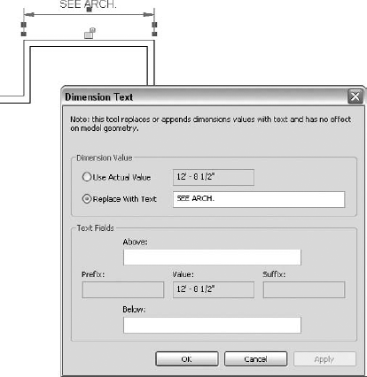
In many cases you will also want the dimension to remain, but you will want to add a suffix or prefix onto the dimensions such as 5′-0″ TYP. In that case enable the Use Actual Value radio button, and then type your text in the Prefix or Suffix box below.
Existing dimensions strings can be adjusted using the Witness line controls. They can be reassociated so that you can add or delete segments from an existing string. Used with dimensions to walls, they permit the user to toggle between the faces and the centerline of the wall.
You now have a basic idea of how dimensions work. The next section will introduce you to adding spot dimensions and coordinates into your project views.
Spot dimensions come in two forms: spot elevations and spot coordinates. Each one can be configured in a variety of ways, using leaders with or without shoulders (horizontal lines). There are also many leader end options to choose from. If space gets tight on your plan or section, you can drag the leader to a new position (see Figure 9.6). The leader symbol will also rotate with objects.
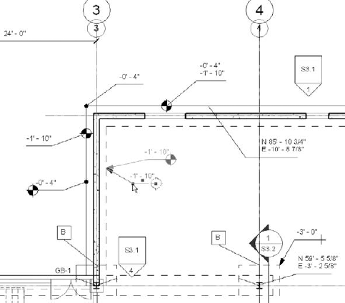
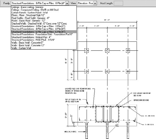
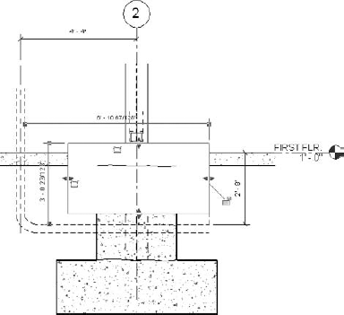
Spot coordinates can display the top elevation, the bottom elevation, or both for a particular model element and are especially helpful in documenting concrete monolithic buildings. Once you place the spot dimension, you can use it to later change the position of the object simply by changing its value (see Figure 9.7). To edit the top of a footing, follow these steps:
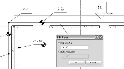
The spot coordinates cannot be edited in plan view once they are placed. The display is controlled by default through the Units Format setting, or it can be overridden (see Figure 9.8). Spot coordinates can be shown in a variety of formats, from metric to decimal to feet and inches, with various options to suit just about everyone.
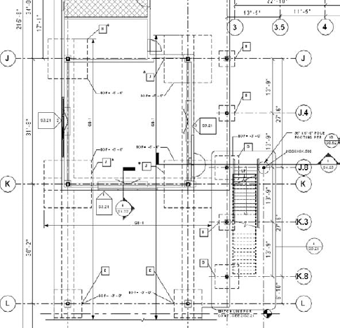
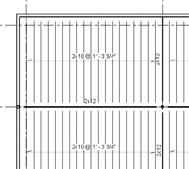
Grids are an essential feature to understand. They are the basic horizontal constraint system in your model plan views. Model elements such as columns and girders can be anchored to them. When a gridline moves, those elements anchored to it also move, providing your model the ability to flex as design changes occur. Once created, they then automatically are generated in any view in which they intersect, saving you a lot of detailing time. That can be a two-edged sword, though, because managing them in the multitude of views that you use for your documents can be a frustrating task, though it is still better than in conventional CAD. Revit Structure has features to control the display in order to make managing them easier. And do not forget that the grid head can be configured as a circle, hexagon, or diamond shape, however you might prefer.
You will now examine the basic control features of grids, how to propagate grid layouts among various views, and how to use scope boxes to control their extents.
Figure 9.9 shows an existing gridline and bubble with the controls displayed. A check box allows you to turn the grid bubble off or on at each end depending on how you want it shown in your view. Clicking the elbow symbol jogs the gridline so that the grid head can be dragged to a new position without moving the gridline itself, an important capability when you have numerous gridlines close together. By clicking on the grid text, you can change it on the fly. As you place the grids, Revit Structure numbers or letters them sequentially to make their annotation more automatic.

Notice in Figure 9.9 that the left grid head has a 2D control below it, while the right grid head has a 3D control above it. When you enable the 2D option, the grid length becomes specific to that view only. With the 3D bubble enabled, changing the gridline end in one view will also change it in every other view in which it intersects. As stated earlier, you can spend endless time moving grids back and forth on your views, so be aware of how this feature works. This is part of the frustration we were referring to when we said a user does not fully understand this feature and ends up spending too much time having to adjust the grid displays in other views.
Once you have placed grids on one view, say your first floor and foundation plan, and you have configured and located the grid bubbles to your liking, you will want to automatically duplicate that grid layout in other views. If you go to those other views, the grids will be there, but they may not be configured exactly like the foundation plan. To accomplish this goal, you use the Propagate Extents option, as follows:
Select an existing grid in a plan view, and then click the Propagate Extents button on the Options bar.
When the Propagate Datum Extent dialog box appears, check the views where you want to duplicate the grid display arrangement.
Click OK.
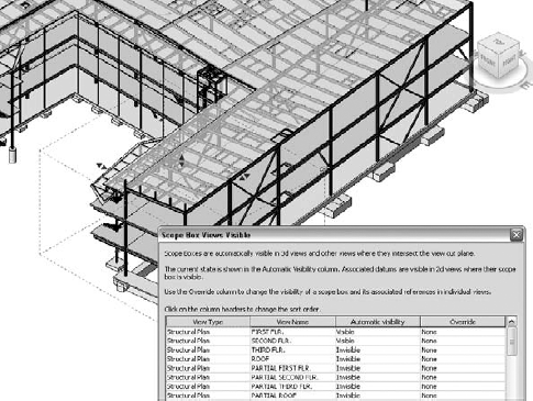
Scope boxes are another way to control the display of grids and other datum elements in your project. Say you have a three-story steel structure sitting on a one-story concrete parking level, and suppose that the parking-level column grid layout is different from the one for the steel structure. By enclosing the concrete level in a 3D scope box, you can limit the propagation of gridlines so that in your views of the steel structure you won't have a confusing overlay of two grid systems. You use the scope box to limit their appearance in views. To add a scope box, go to a plan view and do the following:
On the Create panel of the View tab click the Scope Box icon.
On the Options bar give the scope box a name and a vertical height.
Then draw a rectangular region that you want to control with the scope box.
After placement, select the box and use the blue shape handles to further refine its exact extents.
To make further vertical adjustments to the scope box, go to an elevation, section, or 3D view, and adjust the box using the handles.
To override the scope box's visibility and its associated references in a particular view, select the box and then click the Element Properties

Click Edit in the Views Visible parameter, which displays the Scope Box Views Visible dialog box (see Figure 9.10).
In the Override column, change the value from Visible to Invisible (or vice versa, depending on what you require).
Close the dialog boxes.
To enable the scope box in a view, follow these steps:
Note that enabling the scope box will also limit the visibility of the entire view to that area and that the view crop region will become locked to it. One of the unsung benefits of scope boxes is that they are excellent for managing the size of partial plans for multifloor buildings. Each view will show the same part of the building consistently.
Reference planes have numerous uses. They establish two-dimensional infinite work planes in the three-dimensional space of your virtual environment, to which you can then attach your model elements. If you move the reference plane, the attached objects will follow. They are also a vital part of the parametric family-creation process. For more on this subject, refer to Chapters 18 and 19.
In your model you can create reference planes and then set them as your current work plane. If you are working at an odd angle, you can work on elements on that plane while still in a straight plan view. You can then build your elements in a basic two-dimensional approach such as the way you attached roof framing to a sloping diaphragm or reference plane in Chapter 7. Even though you were drawing the members in a plan view, the objects were still drawn on the sloping reference plane. Figure 9.11 illustrates this point with a kicker brace attached to a sloping reference plane. Using the reference planes, you could add numerous braces to the model along the E grid line. Once you have created a reference plane, you should give it a name for easy use and for later identification in the project. To do that, simply select the reference plane and access its Instance Properties dialog box, where you can name it.
Figure 9.11 shows another use of reference planes that was explained in Chapter 7. In this case the reference planes are used to locate the cut of the ends of the angle kicker by using the Cut Geometry tool. This is very useful in detailing. Be careful, though, because if you delete the reference plane, the geometry reverts to its original shape.

Another important use for reference planes is for the alignment of elements that are displayed in multiple views because reference planes are datum elements that can propagate across multiple views. For instance, you can create the reference plane in a plan view, and it will also be visible in your section view.
Now that you have learned about datum elements and how they are used to create your documents, let's look at annotation elements and see how you can put them to work in your project to create a good-looking, well-documented set of drawings.
Now you are going to learn how to add annotation elements to your views. Not only are you creating a three-dimensional model in order to develop your design, but at the same time you are adding documentation so that your views will be ready to be added to your sheet set. Remember that annotation elements are view specific. This section on annotation elements describes the addition of many types of tags that you will need for your documents in order to identify modeled elements such as beams and floors. You must also add text notes explaining details of the design, and as you will see, Revit Structure has it all covered. This section also explains symbols and the procedures necessary to load and add them.
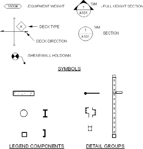
Tags are element descriptors that are attached to and display parameter values for a individual modeled element (see Figure 9.12), such as a beam size or a footing mark. We cannot emphasize enough that you should always use tags, rather than writing text next to an object to describe it. By tagging elements instead, not only does the tag move with the element that needs to be relocated, but its value also updates automatically if you change the element type during the design process.
Three options exist for tagging a modeled element: By Category, Multi-Category, or Material. Of the three, By Category is the one you will most commonly use for structural projects. Tags can be found in the Annotations library installed with the software, with specific structural tags found in the Structural folder.
To add a tag to an element, do the following:
On the Tag panel of the Annotate tab click Tag then By Category from the pull-down list.
The Options bar will display the various tag placement options (see Figure 9.13).
Designate Horizontal or Vertical orientation of the tag.
Click the Tags button on the Options bar, which displays the Loaded Tags dialog box listing all the tags loaded in the current model and in all categories. You can select to make one current, or you can load others from the library directory. The tag listed next to a category is the tag that Revit will use when you select an element to tag.
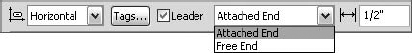
On the Options bar, enable the automatic leader by checking the Leader check box. You can specify that the leader has its end attached or free, and you can set the leader length.
Hover the mouse cursor over the object you want to tag until you see the appropriate tag. Revit Structure will attempt to match the right tag with the element. In "tight quarters" you may need to use the Tab key to get at the element you want to tag.
Click on the screen to place the tag.
As stated earlier, when you move a structural framing member in your project, any attached tag automatically moves with it to maintain its original position in relation to that element. This will allow you to place a structural beam tag at the end of a beam, which then automatically moves and repositions itself as the beam moves.
Revit Structure ships with basic tags for all structural categories. You can also edit and create your own, which inevitably you will need to do in order to adapt the default tags to ones more in conformity with your company standards and for special circumstances. For instance, the normal beam tag might read W12X26. But if you are working on an addition to an existing building, you might want to add an (E) in front of all existing framing to make it (E)W12X26. The wrong approach is to use the normal beam tag and then come back and add the (E) by using a text object in front of it. Instead, you can easily edit the tag and create a new type just for that purpose with the (E) embedded in the tag. Tags support the combination of parameters and text in one label.
Here's the general procedure for editing a structural tag:
Open the tag family either by browsing to the structural annotation library or by selecting a tag that exists in your project and clicking the Edit Family button on the Family panel of the Modify Structural Framing Tags tab.
Once you have opened the tag family for editing, highlight the text label.
Click Edit Label on the Label panel of the Modify Label tab.
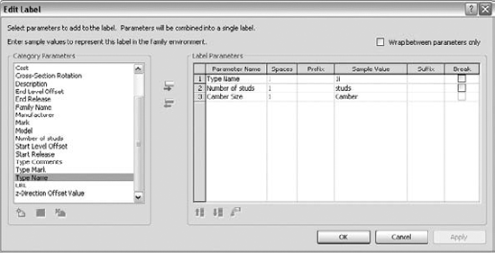
In the Edit Label dialog box select new Category Parameters to add to the label (see Figure 9.14), or edit the existing Label Parameters.
Edit the label by changing the Sample Value field or by adding Prefix and Suffix information.
Enable the Wrap Between Parameters Only check box to create a multiline tag.
Use the Spaces field to increase or decrease the distance between the tag elements.
Once you've completed the label, save your work to a new tag family with an appropriate name, or if you're editing an existing tag, just save it and then load it into your project.
These are the basics of how and why you add tags to elements in your model rather than adding a text note adjacent to an element. The next section shows you how to tag a whole plan at once.
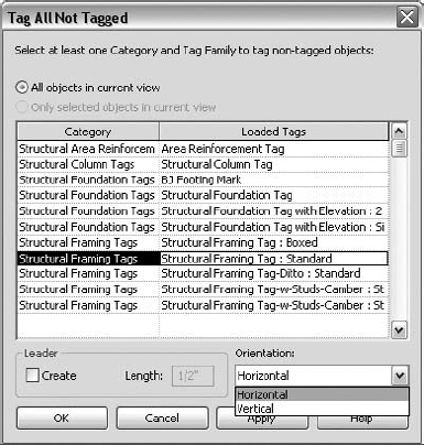
Use the Tag All Not Tagged feature to automatically add tags to multiple objects that do not already have tags in any particular view. It's a very quick way to annotate your views. For instance, sometimes you might find that you need to re-create a plan in your project. At first you may think it a daunting task to reapply all the beam tags to the new plan. Maybe you think it is easier to just edit the old plan. Well, with this option, you can tag all the beams in seconds, so don't worry about the time factor.
To use this feature, follow these steps:
Select the elements you want to tag in a view, or do not select any if you wish all to be tagged.
On the Tag panel of the Annotate tab click the Tag All icon.
Enable one of the radio buttons to either select all objects or select the objects that you previously made to be tagged.
In the Category section, select the type of object tag you wish to apply (see Figure 9.15).
Enable the Create Leader check box, and adjust the leader length if necessary.
Choose the orientation of the tag(s).
It's that easy, so give it a try. Even if some elements are tagged on the view, this function will find only those elements that have not been tagged and add tags to them. Revit Structure will not double-tag any element already tagged.
Exercise: Create a Structural Framing Tag
In this exercise, you will make a new tag for your project to adapt the basic Beam-Stud-Camber label. Your goal is to make the beam size tag display an (E) in front of it, the stud tag to have brackets, and the camber tag to display a c= in front of it, as shown here:
Start a new project.
Level 2 should be the default plan view. If not, double-click Level 2 to make it active.
On the Structure panel of the Home tab click the Beam icon and then draw a beam on the plan.
Select the Beam tool, and then click the Element Properties icon to access the Instance Properties dialog box.
Type 24 for the Number of Studs value and 1″ for the Camber Size value.
Click OK to exit.
Note that the stud and camber values do not display in the tag because by default the Standard Beam tag does not contain labels for them.
Select the tag.
In the Type Selector drop-down list on the Modify Structural Framing Tags tab, choose Structural Framing Tag-w-Studs-Camber: Standard to change the tag type so that the values will display in the tag.
With the tag still selected, click Edit Family.
Click Yes to open and edit the Structural Framing tag family.
With the tag family open, select the text and click the Edit Label button on the Label panel.
In the Label parameters of the Edit Label dialog box, add (E) as a prefix to the type name.
In the Number of Studs parameter, type [ (left bracket) in the Prefix field and ] (right bracket) in the Suffix field.
In the Camber field, type c= in the Prefix box.
In the Spaces field, increase the distance between elements to 3 for a better display.
Increase the label width to accommodate the new parameters.
Click OK to exit.
On the Application menu click Save As
On the Family Editor panel of the Create tab, click Load into Project.
Select the tag again, and use the Type Selector to specify the new tag type you just loaded.
The Beam System tag (see Figure 9.16) covers a whole bay of in-fill beam elements and indicates the common beam size and spacing of members in the framing bay. This tag is especially useful for wood framing where members are closely spaced; typically at 16″ center-to-center and where tagging each individual member would totally clutter the plan. Click Beam on the Symbol panel of the Annotate tab, and then hover your cursor over the beam system until it becomes highlighted. Click to place the tag in an appropriate spot in the bay. Like most things in Revit Structure, this is a tag family, so you can create other types as you need them.
The Span Direction tag is applied to structural floors as they are created, or it can be added later. The filled half-arrow (see Figure 9.17) indicates the direction of the deck, while the open arrow represents the extent of the deck. The Span Direction indicator is important in steel details and sections because, once it is applied in plan, it will enable the display of the metal deck flutes correctly in section, making your sections much easier to generate.
To change the direction of the deck, highlight and rotate the tag 90 degrees. Once the tag is placed properly, you can erase it and the deck flute orientation will not change. Unfortunately, the tag works only for floor objects and not for roofs. The deck profile cannot be added to a roof type and must be drawn manually within sections using a metal deck repeating detail, which is much more time consuming to create and maintain.
Path and Area Reinforcement tags (see Figure 9.18) are added to concrete plans to indicate reinforcing patterns much like the Span Direction tag does for floors. For more information, refer to Chapter 10.

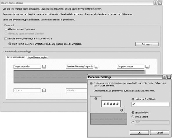
The Beam Annotations tool is an advanced tool for adding beam tags, spot elevations, and text notes to all or selected beams in a plan view. For instance, you can add framing tags to the middle of the beam, and you can add beam end spot elevations to the start and end of the members—all automatically. Figure 9.19 shows the Beam Annotations dialog box and its related Placement Settings dialog box. Each dialog box contains many placement options that you can set to meet various conditions.
To add a beam annotation, use the following procedure:
Go to a plan view where you want to annotate the beams.
On the Annotate tab of the Ribbon click Beam Annotations to access the dialog box.
In the Placement area select by enabling the check box to remove existing tags if you want to replace current ones.
Click the Settings button to configure the placement of the tag in relation to the text bounding box.
In the Annotate Location and Type area of the dialog box, select either the Level Beams in Plan or the Sloped Beams in Plan tab.
In either of those tabs configure the boxes in the schematic layout to show the Annotation type you want to use.
Finally, click OK to exit the dialog box, and the beam annotations will be added to your view.
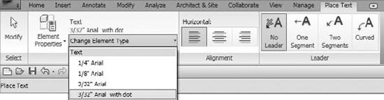
Not every element can be tagged in your project, such as lines and filled regions, so you must add text notes on various views (see Figure 9.20). As with other families, the text family is populated with many text style types formatted for your particular company needs and uses.
To place a text note in one of your views, follow these steps:
Click Text on the Text panel of the Annotate tab.
Select the text style you want to use from the Type Selector (see Figure 9.21).
On the Place Text tab
On the Place Text tab, select the text leader type: No Leader, One Segment, Two Segments, or Curved.
Choose from two placement methods:
Click once to place the top-left point of the text block in your view, and then begin writing. This will make one long text box.
Click the top-left corner and drag without letting up on the cursor to pick the bottom-right corner. This will result in a specific box size with text wrapping. Remember to avoid adding hard returns or the text string will not wrap correctly when the text box size is adjusted.
After you create the text box, the Format panel will appear, so you can make all or a portion of the text Bold, Italic, or Underlined.
Click outside the text box to complete the text string.
To edit the text string in one of your views, use this process:
Click to select the text string.
Pick the move grip in the upper-left corner and drag to reposition the text object.
Click the rotate grip in the upper-right corner and drag to rotate the text object.
Click and drag the grips on the sides of the text box to resize the text box.
Click either of the two leader line grips and drag it to reposition the leader line.
To edit the text itself, click into the text box and change the text as desired; then click outside the text to finish editing.
To add or remove leaders from the existing tag, highlight the tag that activates the Modify Text Notes tab. On the Leader tab click Remove Last to remove leaders as required.
One important consideration for your text styles is whether the background of the text box will be transparent or opaque. An opaque text box will hide what is under it. You will need to decide which way you prefer to show your notes. Covering up what is beneath can lead to problems if it covers up something important. But sometimes that might be precisely what you want. There is a Type parameter that controls this value, and you can adjust each text type as you see fit.
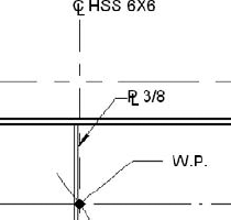
What about special characters in text strings, such as the centerline, plate symbol, or round symbol? They are important to structural annotation, and there is no text equivalent that can be easily used for the centerline or plate symbol. A centerline family is available, but it does not work in a text string, so you will need a workaround for that one. Many times, you will want an annotation that says something like "Centerline W18x" or "Plate 3/8" (see Figure 9.22) that includes the symbol along with some descriptive text next to it. The best thing to do is make your own annotation symbol.
To make your own text annotation symbol for the plate text symbol, do the following:
On the Application menu click New
Select Generic Annotation as the type.
Create the P and the L letters with transparent text and arrange them to make the symbol.
Create a label next to the symbol for the text addition.
Make the text string left justified.
Save and load the family into your project, and save it to your own annotation library.
To use the symbol, drag it from the Annotation area under Family in the Project Browser, and click to place. You can also access the command on the Symbol panel of the Annotate tab.
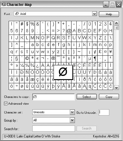
For some special characters, such as the round symbol, you can use the Windows Character Map, found in the Windows Start menu, under Accessories
Open the Character Map and browse through the symbols until you find the one you want.
Highlight the symbol and click the Select button.
When you finish selecting, click Copy.
Switch back to the text string you are editing and paste in the characters (press Ctrl+V to paste).
Some characters have a Unicode value that can be seen at the bottom of the Character Map box, in which case you simply add that number in the text string.
Note that the numbers have to be entered using the numeric keypad. If you just use the numbers on the regular keyboard, it will not work. For laptop users it varies from laptop to laptop, but probably you have to invoke the numeric keypad using the FN key to get it to work.
Revit Structure handles text notes efficiently and effectively, as you have just learned, but sometimes you need to add large sets of notes. The next section will show you how to approach that task.
General notes are text but require different attention than the notes we have been discussing. General notes usually take up a large part of your first sheet in a design set of documents, and they can be heavily formatted. They can be difficult to manipulate into rows and columns and to maintain on the sheet in the way you would like them displayed. But tools are available within Revit Structure that will help to greatly reduce your effort in managing your general notes.
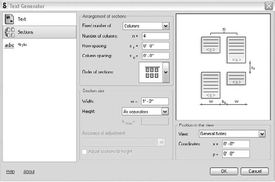
If you are a subscription member, you will have access to the Revit Structure Extension Text Generator, and you will undoubtedly want to start using it immediately. When you activate the command, a dialog box opens that allows you to insert and format your notes and configure how the notes will be displayed in columns and rows on the sheet (see Figure 9.24). You can open Microsoft Word documents directly from the Extension Text Generator. This is just one of a whole set of excellent extensions that Revit Structure offers. If you've struggled with AutoCAD text for many years, you'll find this function to be a breath of fresh air!
The Extension Text Generator has a text import window where you can break notes into sections on the sheet and a style area where you can create and edit the text format.
Here's the general procedure for using the text editor to import a DOC file (you must have Revit Structure Extensions 2009 loaded on your computer):
Click Tools
Double-click Text Generator in the Miscellaneous section to start the application.
In the upper-right area of the Text Generator dialog box, click the Select button and browse to the file you wish to import.
Select and import the file.
Add separators where you want to break the text lines into rows or columns.
Click Sections.
Enter the number of rows or columns into which you wish to arrange the notes.
Adjust the row, column spacing, and order of placement for each section.
Adjust the section width.
For the height of sections, you have two options:
Use the separators that you added in the text part of the dialog box.
Set the value to Maximum. Then you can set a maximum height for the section.
Add the drafting view name for the notes and add a position (or you can just drag the note into position after import).
Click the Style button to access and apply text styles to the notes.
When you have finished, click and Revit Structure will generate the notes as a drafting view.
Drag the notes onto your sheet (see Figure 9.25).
You will most likely have to fine-tune the notes to fit precisely. To edit the notes, go to the drafting view and click the Extensions Modification toolbar.
Keynote legends report or summarize any keynotes that are present in the views that share the same sheet with the keynote legend.
Keynotes are a system of notes defined in an external text file that are applied to elements in your project and then displayed in a keynote legend or list on the side of the sheet. Keynote legends report or summarize any keynotes that are present in the views that share the same sheet with the keynote legend. This can be an effective way to annotate your details in that you can apply keynote tags to objects to display the element type, the material type, or references to a keynote in the keynote schedule. For a complete description of keynotes, refer to Chapter 11.
Component symbols are used to provide a 2D graphic representation of an annotation or model element in your project such as a scale bar, a north arrow, or a wall type. They maintain their printed size regardless of view scale. As with other families, you can edit or make your own new symbols. It is important to build and manage a good symbol library as you transition into the Revit Structure environment. Moment frame connections (solid triangles) are an example of symbols, as are weld symbols and section marks. Figure 9.26 shows pile cap information in a legend.
Legend components are another especially useful type of symbol that you can use when you are preparing a legend (see Figure 9.27). These are not "symbols" in the same context as the Symbol tool discussed previously. They are tied to actual families in the project that will appear in the legend but not get counted in the database as a schedulable element. You can drag loaded components into your legend view. You can configure the symbols to display in any detail mode and either in plan or elevation view.
Creating a legend (see Figure 9.27) is an important task that most projects require. Model, line style, materials, annotation, and phasing symbols can all be added as well as any element that you can place in a drafting view such as lines and text. You can easily assemble a legend view by dragging the symbol and legend components into it, as well as detail and model groups. Legend views also have the unique capability that they can be dragged onto multiple sheets. No other views can do that except schedules. To create a legend for your project, do the following:
Click the Legend icon on the View tab of the Ribbon, and then choose Legend from the drop-down list.
Give the legend a name and scale.
On the Annotate tab, click Symbols.
On the Place Symbols tab, drag the symbols you want from the Type Selector into the view.
Click the Components icon on the Annotate tab, and then choose Legend Component from the drop-down list.
Select an item from the Component drop-down list.
On the Options bar, choose the View type and Length for the legend symbol (if applicable).
Place the component in the view.
Add any other detail or group components to the view.
Create descriptive text next to each item.
Drag the legend view onto a sheet.
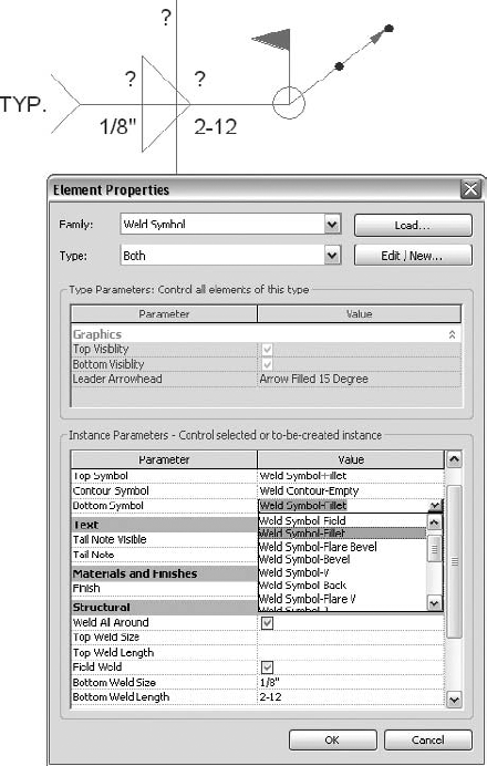
Weld symbols are loaded in from the structural annotation library. You access them for insertion in the Families area on the Project Browser or by choosing the Symbol command on the Annotate tab. Unfortunately, the Revit Structure weld symbol that ships with the product is a bit clumsy and awkward to use. The symbol itself is too big. And for some strange reason, there are 0″ values inserted for all the fields that must be cleared every time you use the symbol. You will probably find yourself trying to edit the family when you start working with it, or you will be looking on the Internet for better families that others might have shared. What is needed is a graphical dialog box that allows you to fully and easily configure the symbol before you place it. It is a bit astonishing that the developers have not found the time to improve such an important symbol for all who are documenting a steel structure.
To use the default symbol, follow these steps:
Choose Weld System Both, Bottom, or Top from the Family Annotation area in the Project Browser (or use the Symbol command).
Drag and place the weld symbol into the view.
Highlight the weld symbol.
On the Modify Generic Annotations tab, click the Element Properties icon, and then choose Instance Properties on the drop-down.
In the Instance Parameters area, edit the Top Symbol and Bottom Symbol values as required (see Figure 9.28).
Add tail notes, finishes, weld sizes, the field weld symbol, the all around symbol, and others as required for your detail.
Use the Symbol Left check box to orient the leader line to the left or right of the symbol.
Click OK when you have finished.
Many of the values can also be added or edited by highlighting the weld symbol after placement and clicking into the text fields.
That concludes our section on annotation. A well-annotated set of documents is vitally important in project preparation. As you have seen, Revit Structure offers lots of help for you in this area as you are creating your documents.
Now let's move on to adding 2D detail elements to your various views. You will do this in order to show those elements you did not want or could not model.
Drafting views have no model elements in them. They are strictly two-dimensional views where you use traditional CAD tools to draft a detail. Section, callout, and elevation views, on the other hand, contain elements from the model as well as additional 2D detail elements. Detailing your project requires working with both element types.
If you or your company has a subscription contract with Autodesk for Revit Structure, you can download an excellent command for detailing in the Revit Structure Extensions for 2010: the Freeze Drawing extension. Any section or elevation with model elements can be turned into a drafting view. All model lines are copied and become detail lines in a new drafting view. If you are worried about shifting model elements or wish to make a typical detail, this extension will fit the bill.
Beyond using linework, you will find that Detail Component elements help you complete your sections and details. You can add those objects that you decide are not necessary to model as 2D elements to your detail views. For instance, you will model the steel column and the spread footing in your project, but you may want to show the base plate, bolts, and grout as a 2D detail group of components in an enlarged section. That is probably the case if you are working for a structural design firm where you are interested in showing only the various typical types of elements. If you are working in a structural detailing firm, on the other hand, you may choose to model all the connection elements so that they can be detailed and scheduled into piece lists.
The following sections introduce you to the various tools that you will use time and again to complete your details.
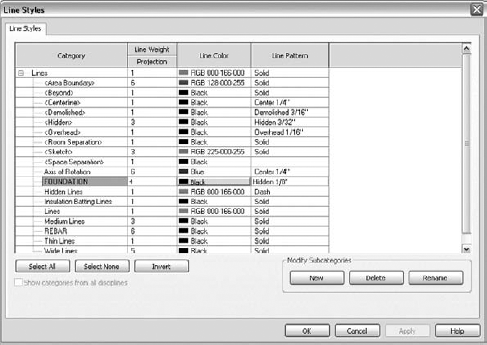
Detail lines are the basic line drawing tools that you will use for 2D detailing. Use them to finish drafting views that are cut from the model and 2D drafting views as well. On the Manage tab click Settings, and then choose Line Styles from the drop-down to access the dialog box that enables you to edit existing line styles and create new line types (see Figure 9.29). These line styles are used not only for detailing lines but also for the Linework tool. With the Linework tool, you can change the line style of most model lines if they do not display as you prefer.
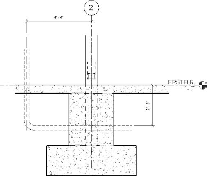
Detail lines can add important information that you might not want to model, such as piping through footings (see Figure 9.30).
Filled regions are sketch based and provide hatch patterns that you use for detailing purposes (see Figure 9.31). The patterns must be sketched as a continuous boundary of lines. You then select a hatch pattern to apply to the enclosed area. The boundary element can be invisible, or each segment can be visible and use a different line style.
To add a filled region to your view do the following:
Click Filled Region on the Annotate tab.
On the Create Filled Region Boundary tab use the Draw tools to create your region boundary, and then click Finish Region.
Select an existing region type or click Edit Type to edit or make a new type.
Click OK until you exit the dialog box, and then click Finish Region on the Region panel to finish.
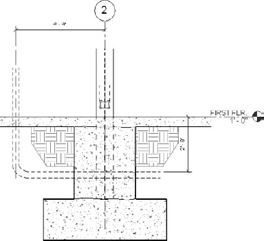
Repeating details are useful in a detail view when you're adding repetitive 2D elements such as punched steel studs, 2D concrete reinforcing in section, metal deck flutes in section for a roof, or masonry block wall coursing along a line (see Figure 9.32). They are another form of component symbol. You can easily space detail components at intervals of your choosing and apply them by specifying start and end locations.
To add a repeating detail to your project do the following:
On the Detail panel of the Annotate tab click the Component icon, and then choose Repeating Detail from the drop-down list.
In the Place Repeating Detail tab select a detail component from the Type Selector.
To make a new Repeating Detail type, click Element Properties, and then choose Type Properties from the drop-down list.
Note that you must load in the particular component that you will use for the new type before starting the Repeating Detail command.
In the Type Properties dialog box create a new type, specify the component in the Detail parameter, and then specify the Layout type as well as a Spacing value for the repeating pattern.
Click OK to exit, and then draw the new pattern.
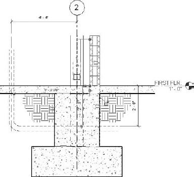
Many times in your struggle to make model elements in a view display correctly, the best practice may be to cover a problem area and to finish in 2D. That is where the Masking Region function becomes useful (see Figure 9.33).
Detail components are 2D representations of model elements, such as wide-flange beams in section that can be used in detailing views. Detail groups are assemblies of detail components that you want to use more than once. You will be able to drag them into your views from the bottom of the Project Browser for easy insertion.
When you are cutting a section on your model, you want the section to be as complete as possible without adding lots of detached 2D lines and detail components. When the model elements move during the design process, the detail components usually do not move with them. Therefore, it can be quite time consuming to continue editing and relocating these elements as the model flexes. One way to avoid this is to build the detail components right into your model family. That way, they are automatically added and can be easily displayed in your section work, and they will move with the model element in which they are embedded.
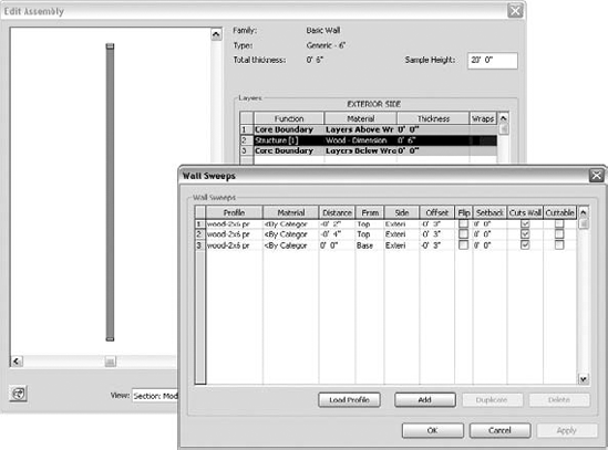
A good example of this approach is the creation of a standard 2 × 6 wood-bearing wall type. In a section view you add the top and bottom wood plates as 2D components to the wall representation (see Figure 9.34). You do that by creating a profile for the flat 2 × 6. Within that profile, you add a 2 × 6 detail component. That profile is then added to the wall type.
The following general procedure will lead you through this process. First you create the required profile for the 2 × 6 flat stud plate:
Start a new project.
On the Application menu click New
On the Insert tab in the profile file on the Load from Library panel, click the Load Family icon.
Next load in the component. In the Imperial Library section, select Detail Components and then Div 06-Wood and Plastic.
Select 061100 – Wood Framing, and then choose Nominal Cut Lumber – Section for the family.
Click Open and then specify 2 × 6. Click OK.
In the Ref. Level plan type ZE (keyboard shortcut for Zoom to Fit) if you do not see crossed reference planes.
On the Create tab on the Detail panel, click Detail Component, and place the 2 × 6 at the intersection of the reference planes.
On the Detail panel click Modify.
On the Detail panel click Line, and then draw and lock lines over the 2 × 6 exterior lines. (These are the actual profile lines.)
Select the 2 × 6 and rotate it 90°; then center the 2 × 6 on the vertical reference plane. Move the bottom line of the 2 × 6 up to the horizontal reference plane.
Select the detail component. Click Visibility Settings on the Visibility panel of the Modify Detail Items tab. Deselect Course and click OK.
The profile is now complete. On the Application menu click Save, and save the file as
Wood – 2x6 profile.On the Family Editor panel of the Create tab, click Load into Project. Then select the new project you started earlier in the exercise (open or start a new project first if necessary).
Now you add the profile with the embedded component to the wall family definition:
On the Structure panel of the Home tab click Wall; then choose Structural Wall from the pull-down.
Click the Element Properties icon, and then choose Type Properties on the Place Structural Wall tab.
Click Edit
In the Edit Assembly dialog box, click the Preview button.
From the View list choose Section: Modify Type Attributes in order to get a sectional view of the wall.
Click Sweeps, and then click Add to insert a new profile.
In the Profile field, select the wood-2 × 6 pr profile.
In the Offset field, change the value to −3″. Click Apply. Notice that the profile is visible at the bottom of the wall in the section preview to the left.
Click OK until you exit all the dialog boxes.
Now draw a portion of the wall in plan view. Create a section view through the wall. When you open that section view, you will not see the flat stud plate at the bottom of the wall. That's because the view is using the Coarse detail level, and the Visibility option for that mode was turned off in the profile family. On the View Control bar, change the detail level of the section to Medium, and you will immediately see that the detail component appears at the bottom of the wall. For added practice go back, and using the same procedure add the two top plates to the wall definition. Notice that the From parameter offers options for Top and Base. This makes it easy to tell Revit the sweep should start at the top of the wall as a reference instead. When completed, your wall should display in section like Figure 9.35. And there you have it.
Using embedded components is the best practice for detailing. Now if the wall moves, the embedded detail components go with it. A further refinement of this procedure would be to create a profile that uses the flat 2 × 6 stud we created and also adds a bolt detail component. That profile would then be specified at the bottom of the wall to indicate the connection of the wall to the floor concrete. Chapter 19 takes this wall family even further by creating a full wood shear wall that displays well in both plan view and section view without a lot of added 2D work to complete it.
Now that you have an idea of how to use detail elements, let's explore how to create and manage typical details.
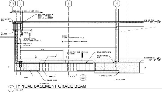
Typical detail preparation is a vital task in documenting any building project, and there are several ways to approach it in Revit Structure. One way is to capture sections from the model that you can then generalize to cover many typical conditions, such as typical foundation conditions (see Figure 9.36). Rather than relying on a library of sheets of foundation details, you selectively prepare what actual conditions you encounter, using the model as your guide.
Undoubtedly, you will have a standard set of details in AutoCAD or other CAD program that you will want to create eventually in Revit Structure. Most of these details have no model connection and are imported as 2D information into drafting views in your project.
To avoid becoming overwhelmed with transforming your whole workflow to modeling at once, you may want to keep your typical details in your CAD system for your first few projects. That will give you a blended construction document set of Revit Structure and CAD sheets. The CAD sheets can be managed and printed solely from the CAD program. As your staff transfers skills from CAD to BIM, you can still keep both systems going and keep everyone productive. You can also simply build the details from scratch in Revit Structure.
If you decide to have a mixed set of documents, a good practice is to link the CAD detail sheets into your Revit Structure project but still do all the work in CAD. This approach allows all the printing for the project to be done in Revit Structure. That is an important consideration because it can be difficult to coordinate one project in both formats and have them look the same when it comes time to print. At the very least, you will have to maintain two title block sheets, one in Revit Structure and one in CAD.
Revit Structure has several commands that allow you to import and export drafting views and to create libraries of standard details (see Figure 9.37). They work quite well. You can import or export single drafting views or entire sheets of drafting views. Note, however, that if the sheet has any views with model elements in them, none of the views will be exported. Next you will see how to use these commands.
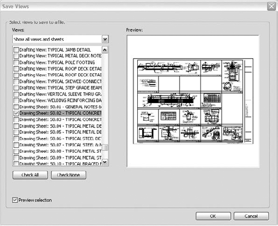
Figure 9.37. The Save Views dialog box allows you to save entire sheets of views or some of the views.
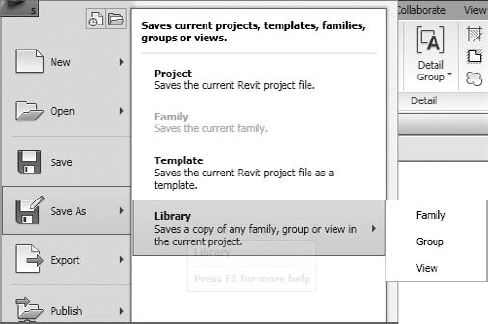
You can save families, groups, and views from your project (see Figure 9.38) with this command. For instance, if you want to save views to a typical details library, do the following:
If you choose just the sheet view, it will be created as a file with all the drafting views included.
Views exported from other Revit Structure files, or whole sheets of views, can be inserted with the Insert from File command. The procedure to insert drafting views is as follows:
On the Insert tab click Insert from File
Browse to the folder and select the RVT file where the view(s) reside that you want to insert, or simply select the sheet you want to insert.
Click OK.
You can also insert 2D elements from a saved model view by using the Insert 2D Elements from File option. This option allows you to copy 2D detail components such as repeating details and filled regions from a view that contains model elements.

That ends our discussion on documenting your model. It is a huge subject that could fill a whole book. With this introduction of some of the most vital factors of documentation, you now should have some direction on how to prepare your projects. Remember that documentation is half the battle and must be carefully planned and executed in order to maximize the use of your model.
- Add datum elements to your detail and section views
Datum elements are necessary for your model because they are the anchors for your objects. Grids, dimensions, spot dimensions, and reference planes are basic constraints for elements within the model, and they give it the ability to flex as you are working through changes in the design of the structure.
- Master It
Datum elements form the basic constraints for your project. If you want to manage the columns and framing members of your project, which kind of datum is best suited for this purpose? What datum element is intended to define the vertical information like floor-to-floor height in your project?
- Add annotation elements such as text, tags, and symbols
Once the model is moving forward in development, you need to efficiently add identifying tags, beam annotations, and text to your various views in order to document your design and prepare your sheets. Tagging elements is an essential task since it taps into the properties of the object. If the object changes type, the tag automatically updates. That then allows you to use the model as a physical database for building schedules of many kinds. Text and symbols also are used to further the documentation of your model.
- Master It
Open
Dataset_0901_Begin.rvt(from the book's companion web page atwww.sybex.com/go/masteringrevitstructure2010), and then go to the second-floor plan. On the second floor, load and tag all steel members. Add a Beam System tag to at least one bay. Add a Span Direction tag to the floor. Go to the first floor and tag the columns. After placing the tags, highlight and use the grips to align them with one another for a better display. Add grid dimensions.
- Add detailing elements such as detailing lines and filled regions
Not everything should be modeled. It takes experience to find the correct level of modeling in your project. For instance, columns are modeled but base plates are not in a typical American design firm. But when taking sections and creating details, you have to add that information in 2D over the modeled objects. So you add detailing lines to show the column base plate and perhaps some earth hatching around it. These are detailing elements.
- Master It
Open
Dataset_0902_Begin.rvtand then go to the callout of Section 6. Add detail lines to show piping 4′-0″ to the left of the column going through the slab, turning 90 degrees, and going through the slab. Use a hidden line style. Add earth hatching below the slab using a filled region. Add a repeating CMU component wall to the right of the column with its outside flush with the grade beam below.
- Create a typical details library
A critical task to accomplish if you want your project to be totally documented in Revit Structure is the management of typical detail libraries. Typical details can be imported from the 2D CAD library or created from scratch in Revit Structure. You import Revit Structure details individually as drafting views, which are then added to sheets. They can also be inserted as part of a whole sheet. In similar fashion, you can export individual drafting views or sheets of drafting views to use in another job or to add to your Revit Structure library of details.
- Master It
You have a new project to start and want to transfer your model and drafting views from an already completed project. How will you transfer the drafting views to the new project? What is the best way to transfer a section with model elements in it to another project as a typical drafting view?