
In this chapter, you will discover how simple it is to get your company's "look and feel" back into your documentation. With Revit Structure you can develop templates that ensure automatic compliance with standards, while also helping you and your team focus on modeling rather than trying to develop clear and readable drawings.
In this chapter you will learn to:
Ascertain what can and cannot be done easily
Enhance your model through customization
Implement model standards and view overrides
No doubt, the first thing you did when you installed Revit Structure was start up the software and begin making a basic model. But how did you prepare for that? Did you take a training class? Did you research graphic standard needs? Did you take your AutoCAD Standards Manual and begin mimicking that in Revit Structure? No? Exactly! Well, we have all been there. Take this new product and get it done now. So you model away for a while and then print out drawings. Then your managers take a peek and think "Yuck" when they see how poor your drawings look.
This isn't totally your fault. Most people get so excited about this new application, BIM, and 3D that they forget about the basics. Most structural engineering firms consult for someone else, and there is an expectation of quality in the final product. But unless you carve out development time, the end product will be short in quality. Sure, the information will be there and you will have BIM and a nicely coordinated set of documents. But do these drawings convey importance? Can you tell the difference between a concrete beam and a masonry wall?
As you begin to delve into the following sections, you will expose where most of our standards come from and how to develop a plan for standards. Then you will touch on typical standard containers like fonts. You'll round off this section by examining line styles and patterns.
When talking with other Revit Structure users, we've found that the subject of standards often crops up. Nearly everyone has some prior history with AutoCAD. If that is your history as well, then you are probably familiar with .LIN, .PAT, .CTB, and .STB files. These Autodesk files have set the stage for standards worldwide for over 25 years. People bought AutoCAD and went right to work using the standards the software offered right out of the box.
Why did the standard from Autodesk become the standard for users? Simple! Because it was hard to create standards yourself and even harder to manage them. If you had the skill to develop your own custom files, you then owned the responsibility to manage them; in the AutoCAD world, those file types contain the standard. See the following list for an explanation of AutoCAD standard "containers":
ACAD.LINIn this file you define line patterns (dot, space, dash, and letters) then load them into a given DWG file to be assigned to objects and/or layers.
ACAD.PATThis file is where hatch patterns (a regular sequence of pen strokes) are defined and then read when used within a given
.DWG.ACAD.CTBYou define color to pen weight here. The file is used only at print or plot time.
ACAD.STBThis file is where you define pen weight names; your
.DWGthen references these names via layer or object overrides.
Seems like a good way to do it? It is, as long as your standards are what Autodesk suggested. But what if you don't like their standards?
If you create new line types or hatch patterns, you then have to provide the
.LIN/.PATfile to everyone who will need to use it for new.DWGfiles. You can put your custom line patterns in theACAD.LINorACAD.PATor a new.LIN/.PATfile. You have to be sure to tell people where the.LIN/.PATfile is stored and to archive it with the drawings.If you customize a
.CTB/.STBfile, you also need to store that file on the network so that the team has access to it when they plot. Be sure to back up your files—if you lose them, you will not be able to plot properly. And make them read-only so that changes won't happen behind your back.
The joy of Revit Structure is that all four of these standard containers are now in your model directly. Don't like a line type? Change it or make a new one and apply it. Want a heavy pen? Assign it where you want. Need a tighter pattern? Make it on the fly and use it right then. Not customizing Revit Structure is almost a crime—it is that easy. So don't just copy your AutoCAD standards; improve them and make them even better! And again, the great thing about Revit Structure is that your customization is contained in the model, so that anywhere your model goes, your standards go along for the ride.
Now that you understand where historically standards have been managed and customized, it is time to learn how to begin to customize standards in Revit Structure.
It is wise to have a plan of attack before you begin. When it comes to standards, you need to know where you want to go and then build the road to get there. In Revit Structure the first step is to determine the line weights you will use for your model. In the following sections you will assign these weights accordingly.
Revit Structure has 16 "pen slots" you can define and use. In early versions of AutoCAD, you had 16 pen options, so to some, this will be familiar. As shown in Figure 17.1, the pens are simply numbered 1 through 16. The Model Line Weights tab lets you assign weights for model objects in orthogonal views such as plans and elevations.
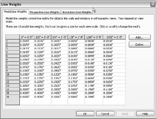
Now as you look at this dialog box, it may seem a little expansive with all the various scales. Don't let this deter you—all the various scales are not important, and you really don't need them. The scales listed provide a means of controlling differing scales. But if your standards are like most, you will apply the same pen sizes to every scale option. An exception, however, can be made for certain types of plan work. Imagine you have a
The default setup provided in Revit Structure has a series of sizes ranging from 0.003″ to 0.5″. It is uncommon, to say the least, to see a
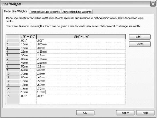
If you have had manual drafting training, you will recall technical pens. Those ink-filled devices for drawing crisp, black lines on vellum or Mylar did very well back then, and their sizes can still be used today. A popular brand manufactured by Koh-I-Noor offered pens ranging from 0.13mm to 2mm wide. The goal of any line weight change is to offer a visual clue that something is to be seen more important or less important than something else. By proper assignment you can visually layer objects in your drawings, drawing attention to important elements and fading elements that are needed visually but don't have to stand out.
In the construction industry, the most basic drawing is a
Table 17.1. Pen Weights
Pen Slot | Size |
|---|---|
1 | 0.025mm |
2 | 0.13mm |
3 | 0.18mm |
4 | 0.25mm |
5 | 0.30mm |
6 | 0.35mm |
7 | 0.45mm |
8 | 0.50mm |
9 | 0.60mm |
10 | 0.70mm |
11 | 0.80mm |
12 | 1.00mm |
13 | 1.20mm |
14 | 1.40mm |
15 | 2.00mm |
16 | 0.025mm |
I use millimeter (mm) values here (rather than inches) because I am a purist. Back in the day, technical pens used mm values, and to maintain precision, I do so as well. But it doesn't matter that much whether you assign 0.13mm, 0.051″, or 0.05″—only someone with a super laser printer and a microscope could tell the difference. It should be noted that once set, this value will be pretty static and should not change often. So why not be precise?
As for pen 16, it isn't needed for most work, but you could think of it as your "super-thin pen" just in case it prints. You can use that pen slot as a flag of sorts for tracking changes you will make later.
Exercise: Defining Line Weights
This exercise examines the process for filling out the Line Weights dialog box and making adjustments to various scales. Start with a new project based on the default Imperial template:
Under the Manage tab, choose the Settings drop-down and click the Line Weights command.
Select the first column on the Model Line Weights tab and then click the Delete button.
Repeat for all scale columns except

Fill in all sizes, as shown in Table 17.1.
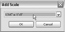
Click the Add button and create a new scale for

Adjust each pen width for the

Which Pens Are Used for Undefined Scales?
If the drawing scale you're using does not have a corresponding scale in the Pen Weights dialog box, Revit Structure will use the closest, or if evenly split between two, the larger scale. For example, if pen 1 for
Using this knowledge, you can avoid having to assign pen weights for all scales simply so that they follow your standards. If you want all drawings to use the same pen sets, create one scale, and every view at every scale will use it.
As shown earlier in the Line Weights dialog box, you have defined two scales for your model objects. Objects shown in
Often referred to as a line type, Revit Structure line patterns are a defined series of dots, spaces, and lines that can convey a purpose. Whereas line weight in an object will indicate importance, a line pattern will help paper-document readers know what they are looking at. A good example of this is a concrete beam below a slab. The lines for beams below slabs are typically drawn in a hidden line type indicating that the beam is, in fact, below.
Users of AutoCAD will access and develop new line types via a .LIN file. This then will be read into an active .DWG to permit use of the line type. If you need to modify an actively used line type in AutoCAD, you first have to change the .LIN code (A,.75,-.125,.125,-.125, for example) in the .LIN file, save, and then reload the file. If you create a custom pattern and then lose the .LIN file, you are out of luck. There is no way to re-create the .LIN from the definition stored in a .DWG. It is precisely this tedious work that has forced the architecture, engineering, and construction (AEC) industry to adopt the standard put forth by Autodesk.
Where Did Revit Structure Come From?
Autodesk did not invent Revit. In fact, other than purchasing the company and then spinning off Revit Structure and setting release cycles, Autodesk has done well to stay out of the way and let the people who created it keep the program moving in a positive direction.
But it is this "separation" that causes some discontinuity. In nearly all cases, you will be using AutoCAD alongside or to support Revit Structure. For example, in Revit Structure the default pattern for gridlines is Grid Line
Revit Structure users have the option to use the standard provided in the software or develop what they want much easier than in AutoCAD. It is impossible to match AutoCAD immediately when you open Revit Structure; you must customize your template to get an identical line style appearance. But I think you should do what you like and what you think looks good rather than simply adopting a graphic standard that goes back 25 years.
To develop standards, look back at old hand-drawn plans, sections, and elevations to see what the hand would typically do. You will notice that hand-drawn lines tended to be more continuous and unbroken than what typical CAD systems display. Knowing why is subjective, of course, but if you think about it, that was probably done for two reasons. First, it took more effort to lift and drop the pencil/pen when creating long lines. But also the drafter often kept the line breaks away from important intersections. For example, the gridline pattern would be continuous at column locations. The dashes would be placed between grid intersections instead. With Revit Structure a 30′-0″ bay will have eight line breaks, using Grid Line
Protecting Custom Standards
You might think about redefining patterns or other default settings in Revit Structure. We recommend that you stay away from this practice. It is easy to create new definitions and just as easy to overwrite them. You could spend time redefining Grid Line
We recommend that you develop a naming protocol to provide a level of safety for your custom styles, patterns, families, and so forth. For example, you could use a # sign as a prefix in front of anything new you create. Not only is it unique (it's not used by Revit Structure), but also it will be shown first due to alphabetic listings. Use this or another character or company initials, but you certainly should not just redefine any out-of-the-box standards.
So the first step to improve your Revit Structure standards is to define a new, longer pattern for gridlines to use and then apply it.
Exercise: Creating a New Line Pattern
This exercise shows the steps to create a new line pattern and then assign it to Grid Line objects. Start with a new model based on the default Imperial template:
Click the Manage tab on the Ribbon. Then on the Project Settings panel expand the Settings button and choose Line Patterns. This will display the Line Patterns dialog box, as shown here:
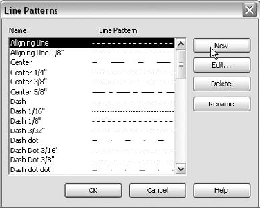
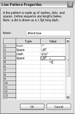
Click New to display the Line Pattern Properties dialog box.
Type #Grid Line as the name, and then use the values shown in the following graphic for the various fields. Click OK to close the dialog box.
Click OK to close the Line Patterns dialog box.
If not displayed already, switch to any
Using the Home tab, click the Grid button in the Datum panel, and create a vertical grid in the center of the drawing area.
Select that grid and then copy it to the right 15′-0″.
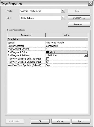
With the new grid selected expand the Element Properties button, and click the Type Properties button on the list. This will display the Type Properties dialog box.
Click the Duplicate button. Name the new grid type #Grid Bubble and click OK.
Once you're back in the Type Properties dialog box, select the End Segment Pattern parameter box, scroll to the top of the list, and choose #Grid Line. The new #Grid Bubble type is now assigned to use the new #Grid Line pattern.
Click OK to close the Type Properties dialog box.
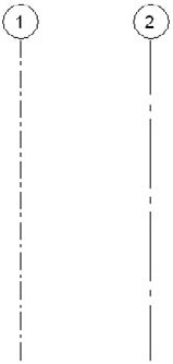
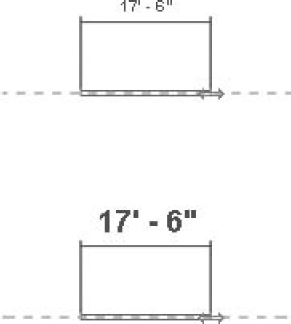
The following illustration is a comparison of the out-of-the-box grid and a new custom grid type; grid 2 now has a much-less-busy line pattern. It is less likely to be misinterpreted as something else, and some find that it's more pleasing to the eye. Also, when placed closely to a hidden line, the grid pattern will not "compete for attention" with the hidden line. Again, this can aid recognition and interpretation.
If you can keep in mind how your models (drawings) look and work to keep them clear, you will make your future drawing reader much happier. It takes a conscientious effort to keep those readers in mind. Remember they don't have a computer display that they can zoom in with to see something more clearly. Developing your standards is a twofold process—creating the style and then applying it.
Revit Structure elements, like columns and beams, are managed in much different ways than grid-type objects. Access to the multitudes of model objects is done via the Visibility/Graphic Overrides and Object Styles dialog boxes. If you want to set how the entire model is displayed, you use object styles. If you want to change only a single view, you use visibility/graphic overrides. In general, try to get the model itself looking right for the majority of views and then, if needed, tweak specific views.
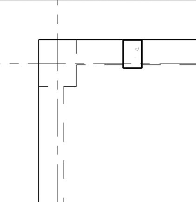
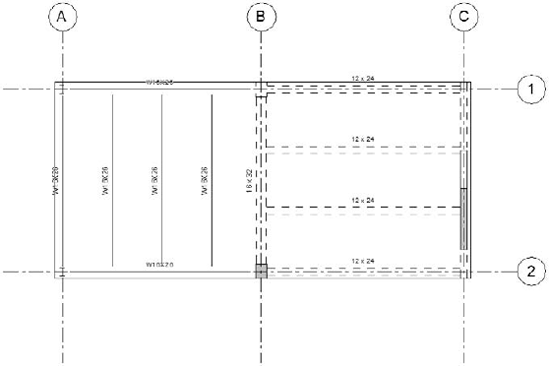
Our first step is to learn what we have to start with. We will create a new model and then make some basic objects: a set of intersecting grids, a concrete slab with supporting beams, and a column below and one being cut by the view range. As shown in Figure 17.2, this doesn't exactly pop visually.
Next, we will adjust your pen weights as described earlier in this chapter. The linework will begin to change thickness—but may not be for the better. That's because we have yet to tell the objects what weights to use!
Then we can create new line patterns for gridlines and hidden line patterns for beams and columns below the slab. Finally, we fire up the Object Styles dialog box and begin to adjust the line weight and line pattern assignments. Once complete, the grids, columns, and beams all should look different and ideally better.
Exercise: Assigning New Line Weights and Patterns
This exercise walks you through the steps to assign line weights and line patterns. Use the book's companion web page at www.sybex.com/go/masteringrevitstructure2010, look in the Part 5 zip for Chapter 17 files, and open Line Weights.RVT. This model has the proper line weights defined as well, containing several line patterns for concrete objects.
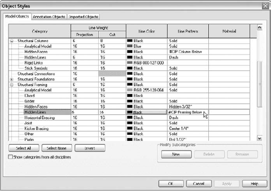
Activate the Manage tab on the Ribbon, and within the Project Settings panel, expand the Settings drop-down and click the Objects Styles command to display the Object Styles dialog box.
On the Model Objects tab, expand by clicking the [+] icons in front of all Revit Structure categories. You will need to use the scroll bar to see and expand all categories.
Click the Select All button. Then use any Projection column slot and change the value to 16. Repeat for the Cut column, and change all Cut values to 16.
Click OK to close the Object Styles dialog box. This will collapse all the categories. Then reopen the Object Styles dialog box.
Select the Floors Projection cell and change it to pen 6 (0.35mm).
Select the Floors Cut cell and change it to pen 8 (0.50mm).
Select the Structural Columns Projection cell, change it to pen 6 (0.35mm), and change the Cut cell to pen 8 (0.50mm).
Now expand the Structural Columns category. Change the Hidden Lines Projection cell to pen 6 (0.35mm). Change the Hidden Lines Line Pattern from Hidden

Scroll down to the Structural Framing category and change the Projection cell to pen 6 and Cut to pen 8. Expand the category and change the Hidden Lines Projection cell to pen 6 (0.35mm). Finally, change the Hidden Lines Line Pattern cell from Dash to #CIP Framing Below.
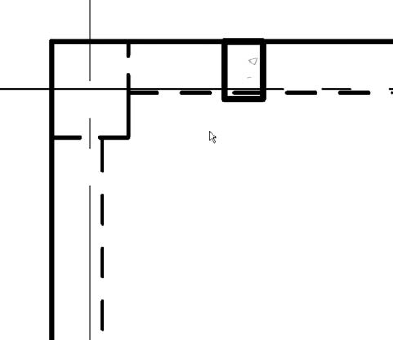
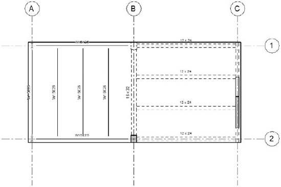
Click OK to close the Object Styles dialog box. Your model should now match the following illustration.
You've made only the beginning steps to control your standards as you see fit. Every cell with pen 16 is a potential location to customize weight. Every Line Pattern cell that isn't set to Solid is a candidate for customization. But take note that sometimes for any given view, an object's hidden lines may be managed via the Hidden Faces category rather than the Hidden Lines category.
It will take some work to fully customize your modeling styles. The key to success is to tackle your model objects one at a time. Some users have gone so far as to set all pen slots to 16 and change all colors to something bold and easy to see, like hot pink. Then they proceed to reset hot pink to black, item by item, from within a model that has all model objects in it. Eventually when they don't see any hot pink model objects, they know they have addressed all projection/cut issues for the objects they placed while they were incorporating their line weight and line pattern standards.
Most of the work in Revit Structure is line work of some sort. Strokes of the pen can convey a great deal of information. But undoubtedly great line work will not do for all. Eventually you will need to provide something that can be read.
Another class of objects in Revit Structure is annotation objects. These are elements that present themselves in only one form for any view; they don't have a cut style and they tend to scale with the active view scale. Tags, level heads, and sections are all annotation objects.
Getting your annotation standards in place isn't as difficult as developing standards for model objects, so temporarily changing the line weight for all projects will reap little reward for the effort. Also, most annotation objects categories are just text, and all text in Revit Structure uses Windows True Type fonts (TTF). A TTF contains the full letter stroke in it, so line weight will have little impact. Therefore, making them any weight from pen 1 to pen 16 will be impossible to notice onscreen.
However, there are things worth customizing. For example, callouts have a boundary box that usually should be a medium line weight as well as unique line pattern. Also, you may prefer that grid heads have a heavier weight for the circle, and there are other examples.
Exercise: Assigning Annotation Pen Weights and Patterns
This exercise quickly runs through the steps to control pen weights and line patterns for annotation objects. Open Chapter 17's Annotation.RVT file (from the book's companion web page). This model picks up where the previous exercise ended, but a callout has been placed around the column.
Activate the Manage tab, and click Settings

Click the New button and name the new pattern #Callout.
Create a Dash type at

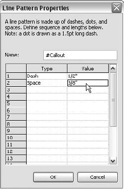
Click OK to close the Line Patterns dialog box.
Choose Settings
Select the Annotation Objects tab.
Expand the Callout Boundary category. Change the Projection line weight to pen 5. Change the Callout Boundary Line Pattern from Dash Dot

Change the Callout Leader Line to pen 5 and also change the Callout Heads category to pen 5.
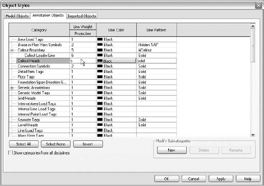
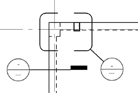
Scroll down to Section Line and Section Marks and make both slots pen 5. Click OK to close the Object Styles dialog box. As shown here, the section and callout symbols are now heavier and stand out clearly.
Obviously this should not be the end to changes to your standards, but you should have a better idea of the connection between the various controls at your disposal. First you define line weights, then define line patterns, and then assign the pair to your object styles so that you get the desired results. This combined pair, known as a line style, is covered in the following section.
Once you have developed your line weights and patterns, you will probably want to use them for non-objects as well, such as drafting lines and detail components. This is done in Revit Structure through the creation and application of line styles. A line style is essentially a set of style controls saved into a single style that can then be applied to numerous objects later.
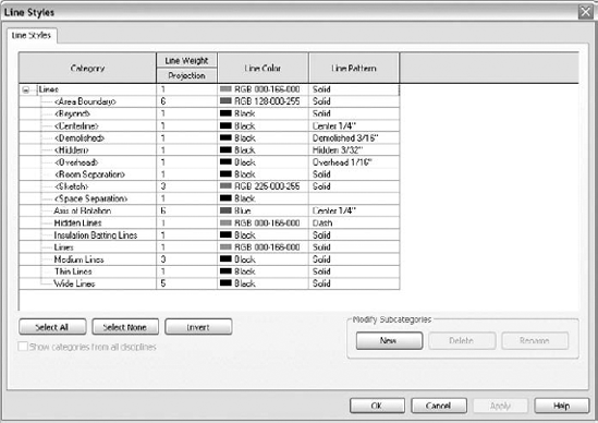
After you have defined your line styles, you will be able to use them not only to draw basic line geometry but also to override an object's native appearance as the need arises. Creating line styles is fairly simple; a line style consists of a weight, a pattern, and a color. Refer to Figure 17.3 for the styles provided with the Structural Analysis-default.RTE file.
Now just as before, you would be wise to keep your standards away from default styles so that they can be protected from being overwritten, but also so that you can keep track of how your standards are organized. For example, there is a default line style named Medium Lines, and it has pen 3 as a weight. However, there is also a generic annotation style named Medium Lines, and it has pen 4 as a weight. These are not the same thing, so this not a problem—technically. But the possibility for confusion is high—unless your customized style is unique and you follow that naming convention across the board. A good policy is to leave everything in place and simply add your customization to a new template and then build on this as needed. If desired, you can purge extraneous styles as permitted by the program.
Exercise: Creating Model Object–Derived Line Styles
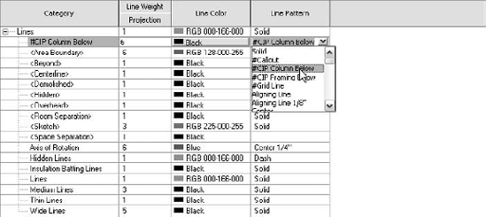
This exercise will step through making line styles based on model object standards. Open the Chapter 17 Line Styles.RVT file (from the book's companion web page). This model picks up where the previous exercise ended. Our goal is to create a few styles for conditions when the model must be "faked."
From the Manage tab, choose Settings
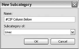
At the lower right, click the New button.
In the New Subcategory dialog box, type #CIP Column Below and click OK.
Locate the new #CIP Column Below line style and change the Projection slot line weight to pen 6. This is the same size used in the earlier exercises for the concrete column line weight in hidden line projections.
Change the Line Pattern setting to #CIP Column Below and click OK to close the dialog box.
Now that you have a style, you can apply it in two primary ways. One is to draw "dumb" lines when and where required. Perhaps you just had a bunch of changes come in, and there isn't enough time to fully model them.
On the Annotate tab of the Ribbon, click the Detail Line button on the Detail panel.
Using the Type Selector on the Element panel, select #CIP Column Below. Choose the Rectangle button from the Draw panel.
Move into the drawing area, to the lower right of the real column below the slab. Create a 24″ × 30″ box shape to match the size of the real concrete column.
Understand that this is poor modeling practice. However, it very well may save the day, and you will go back later and model properly, right? The tool is there for a reason: to aid you in your work. With this tool, you can mimic your concrete columns below slabs. Creating other line styles that match your object style standards will also permit 2D DWG conversion into the Revit Structure "look and feel." Perhaps you are renovating an old AutoCAD-based project; with this procedure, you can import the drawing data and then reassign line work to your current documentation standards for a seamless 2D/3D presentation.
Finally, perhaps you have modeled in 3D but for whatever reason the object style being presented isn't accurate. You can use your line styles to "paint" model objects. Imagine for a moment that the vertical concrete beam on the Level 2 plan view at the last minute was changed to a concrete wall below a slab:
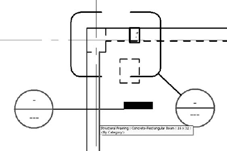
Notice that the line pattern changed to match the columns below. This beam now has the appearance of a column as demanded by a project change but without the hassle of remodeling just before the deadline. Again, this is not the best thing to do as a normal practice but it can be handy. If you end up needing to reset an object, use the Linework <By Category> style. This will clear any painting you may have done. Taking the time to develop line styles that match your modeling line work will not only provide you with a means to clean up problems but also provide a means to draw in 2D just as you model in 3D.
Not everything in proper documentation is line work. Another valuable technique is to use hatching, otherwise known as fill patterns and filled regions.
Known in the AutoCAD world as hatch, filled regions in Revit Structure enable you to provide tone to your drawings. This tone conveys that a simple box is made of steel, concrete, precast, masonry, or some other material. AutoCAD has had a healthy selection of hatch patterns for years, and Revit Structure can leverage them—and more. Not only can you bring in your favorite AutoCAD hatch patterns, but you can also set up patterns for your model that can be used over and over again without keeping track of scale and rotation. In AutoCAD you must determine the scale of the pattern, its rotation, and its layer every time you place a hatch pattern on your drawings. In Revit Structure, those questions are answered when the fill pattern is defined; you decide the scale, rotation, line weight, opaqueness, and color (if needed).
An added perk with Revit Structure filled regions is the inclusion of the boundary in the filled region itself, along with a line style control for the boundary line work. And since filled regions have a type property, also known as a style, if for some reason you want to globally change a given filled region pattern, you can do so and the entire model file will update with the changes.
You can place filled regions in any model view except 3D, and you can place them into legends. A great use is for plan notes and legends on sheets. You also have patterns that are also printed 1:1, known as drafting fill patterns. You also have model fill patterns, which are used to represent real model objects such as tile and masonry stacking.
To define a new pattern or adjust an existing pattern, activate the Manage tab and choose Settings
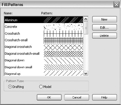
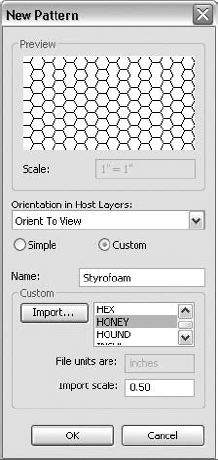
Let's say, for example, you want a honeycomb-style hatch you used before in AutoCAD. That doesn't exist natively in Revit Structure, but you still have your ACAD.PAT file available. Open the Fill Patterns dialog box and click the New button. This will display the New Pattern dialog box. Here you can create a basic line-based pattern or, as in this case, read an existing .PAT file for a pattern. At this point, click the Custom radio button. The dialog box changes to a custom import format, allowing you to browse to a .PAT file (see Figure 17.5).
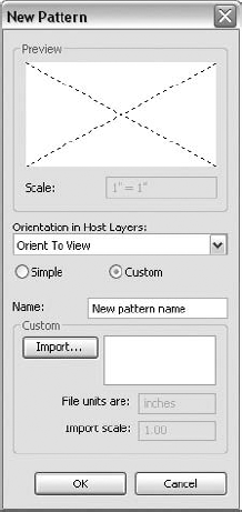
Now, click the Import button to open the Import Fill Pattern dialog box, where you can hunt down your AutoCAD-installed ACAD.PAT file. Normally this is stored in the AutoCADsupport directory—find yours by typing (findfile "acad.pat") at the AutoCAD command line and pressing Enter.
If AutoCAD can locate the file, it will return the directory location. Once you have found your .PAT file, Revit Structure will list all included patterns in the Custom list panel. Next, assign the name Styrofoam and then decide if you want the same 1:1 scale as in AutoCAD. In this case, the hatch scale in AutoCAD is set to one-half the old AutoCAD scale value. Revit Structure doesn't have a DIMSCALE or a scaling problem, so here you can use 0.5 to make the pattern half the size as the 1:1 scale in AutoCAD. Finally, if this pattern was going to be used for something like a wall, then you would adjust the Orientation in Host Layers setting to Align with Element. In Revit Structure your patterns can rotate with any object that uses a pattern. At this stage you are finished, as shown in Figure 17.6.
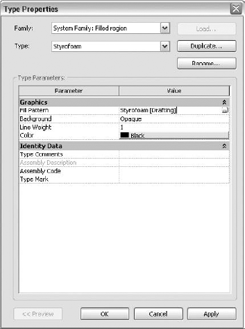
Now that your pattern for Styrofoam is created, you can add it to a new 1:1 Legend view. Once within the view, use the Annotate tab and select the Filled Region button from the Detail panel. The Ribbon will change to the Create Filled Region Boundary tab. This Ribbon contains all sketch-related functions and controls. Zoom in a bit and use the Draw panel Rectangle tool to create a 1 × 1 box. Then click the Region Properties button on the Element panel, which displays the Instance Properties dialog box for filled regions. Since you still need to create your filled region style, click the Edit Type button; then in the Type Properties dialog box, click the Duplicate button and set the name to Styrofoam. Click OK. The dialog box closes and changes the active type appropriately. Next, change the fill pattern to match. You can either use the ellipsis ([...]) button to browse for the fill pattern, or, since you know the name, you can type Styrofoam [Drafting] and Revit Structure will assign it. Then decide whether you want your Styrofoam pattern to always hide other content by using an opaque background or let it overlay with other line work (choose Transparent). If you never want any line work to show through the region, leave this setting as Opaque (see Figure 17.7).
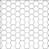
Once you have finished adjusting the Filled Region Type properties, click OK a few times to close all dialog boxes. Back in the drawing area, your rectangle is already done (see Figure 17.8). If warranted, you could change the rectangle line work by selecting the lines and then choosing another type from the Type Selector. In this case you may want the Thin Lines border. Simply click the Finish Region button on the Region panel. Then instantly your box is filled with the honeycomb pattern you defined earlier, and it is automatically a tighter pattern, matching your standards.
Adjusting Content
After you have defined your line weights, line styles, and filled regions, you can then use them on your typical details or other types of families, such as annotation symbols. You have put all this work into your standards, and these features will be applied to any new content in your model. But unless you inject them into your various family files, those nonstandard elements will propagate into your model as you bring them in.
In some cases, depending on the file type, you can use Manage tab
This can be a tedious task, but it is necessary if you are to create and use a truly seamless single set of standards. Keep records of the files you change, or use a separate file structure for your customized files, because new builds and new versions of Revit Structure families come out often and you don't want to overwrite your work accidentally.
Once your project models can create drawings that look good, then it is time to make Revit Structure easier to use! Although you're not making a visual that you can show off to your superiors, a few deft moves of your fingers on a couple of mission-critical Revit Structure support files can free up tons of time later on. Hopefully this free time then can be spent on more customization or learning a seldom-used feature of the program.
In this section we will explore enhancements that can be utilized to improve Revit Structure and your use of it. There is an .INI file where you can tweak Revit Structure to make it more user friendly. You can also empower Revit Structure by adding access to your own custom family files, but do it smart if you do. Also, you can customize tool shortcuts to speed your work with the software.
The Revit.INI file is where Revit presets library folders, obtained during installation or a network installation image. This file contains mostly code that you are better off adjusting via the Revit Structure application menu (the big R) button, via the Options button at the bottom of the screen. However, there are a few gems you can have only by manually editing the Revit.INI file.
First determine where your Revit.INI file is stored, which is no easy task in today's myriad of operating systems. The simplest method is to check out the properties of any Revit Structure 2010 shortcut link on your desktop or in your Start menu. The file will be in the same location as the Revit.EXE file. Please note that you should not make changes to the Revit.INI file while Revit is open.
Once you find the Revit.INI file, it is recommended that you make a backup copy. Once that is done, open Revit.INI for editing with Notepad. Now you are ready for the gems!
No doubt you have noticed how Revit Structure will create many temporary albeit small dimensions as you draw or edit objects. The problem is that this text is somewhat small (8 point) and often can be placed poorly by the software. If you find yourself struggling to read these items, then take advantage of a tweak to make the text size bigger onscreen. Edit your Revit.INI file and look for a [Graphics] section. If it doesn't exist, then create it at the bottom of all the content. On the line following [Graphics], type TempDimFontSizeInPoints=XXXX
As for the font itself, it is very similar to Arial but isn't Arial. In fact, it isn't any normal font on your computer and does not ship with the operating system as Arial and others do. The font characters are defined by a font embedded in the software and cannot be changed.
After using Revit for a day or so, hopefully your Recent Files area will be populated with your recent activities. Although this list may be handy, it may become bothersome to see all those entries every time you start Revit. What can you do? You can hack the Revit.INI file! Somewhere in your file, probably near the bottom, will be a running list of the last eight files you have accessed. This is helpful when working on one project, but imagine if you are working on several projects, but your file-naming convention isn't unique to each project!
This happens more often for families because they usually have similar names but can be customized per project. The problem is that you get only the filename in the list, which makes it easy to pick the wrong file since the folder could be different. Now it should be noted that if you hover over a recent file entry, Revit will provide a tooltip with the full folder path to the file. But that is a tedious method to use.
To fix this is simple; open the Revit.INI file and in the [Recent File List] area simply remove whatever filenames you don't want. You needn't bother with renumbering the ones you leave behind.
If you enjoy this tip, then put a shortcut on your desktop to your Revit.INI file. Then whenever you want to reset your list, open it up and make the change.
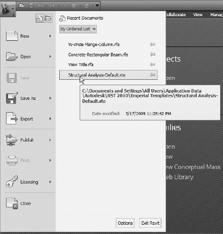
As you can see in Figure 17.10, you can find recently used files within the Application menu.
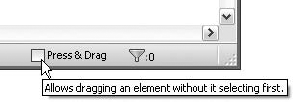
One final helpful Revit.INI edit is a control to set the default status of the Press & Drag feature in Revit Structure. This selection method allows you to select a group of objects with no command active and then, by clicking a point in the drawing area, move them en masse to a new location.
If this seems like a non-issue, then you are not a new user to Revit Structure! More often than not, new users will inadvertently grab objects and move them and in some cases fail to notice. By turning this feature off at the right end of the status bar, as shown in Figure 17.11, you can protect your model from these sorts of mistakes.
So why do the Revit.INI file edit? Revit Structure by default has the feature set to on, or (1). Do you think you can tell your new users and they will remember to shut this off? Probably not, so edit their Revit.INI file before they start and fix this code in their file:
[Selection]
AllowPressAndDrag=0
When Revit Structure fires up, the Press & Drag toggle will be off, thus protecting your user from making press and drag mistakes. Now if they turn the check box on, well, it is on then. Education is key.
You are probably aware of this already, but customizing library paths not only helps to implement standards but also, with proper organization, aids in your management activities. The key is understanding why it is important and then getting consensus on how to organize. Nothing is more frustrating than not being able to find a family you need in order to keep modeling. As you can see in Figure 17.12, the default installation will place all of your library and related family files on your local drive.
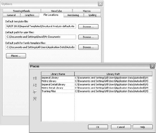
Figure 17.12. The default installation paths for library files found on the File Locations tab of the Options dialog box and the related Places dialog box
The first step is to develop a plan to share your library files across your network. Typically this involves assigning a directory location on your local server where every user has the same drive letters pointed to the same server share. For example, \serversoftware could be mapped to each network user as the S: drive. Then on the server you would place the Revit Structure library files as they exist normally on the local C: drive.
So at this point you have S:Autodesk Revit Structure 2010Imperial Library; you then would have all your fellow Revit Structure users modify their Places dialog box to match the new server locations. Once this process is complete, you and your entire team will share the same set of templates and family files and have a new home in which to put custom files.
All is good in your world, running smoothly, and then after a little time passes you get word about a new build of Revit Structure. As a new and growing industry, Autodesk and the Revit Structure development team are always working on the next release of the program. But sometimes a bug is found, or a fix made, and Autodesk issues a patch to the software. At the same time, they may or may not include new and/or revised family files.
So you install the new build or version and then go to copy the new library files over your existing server located files. But you pause and wonder, what changed? Anything? Everything? What if the name of your own custom family file is now used by Autodesk for a similar family they created? If you copy it over, it will wipe out yours. Did you edit the wide flange catalog file to change the X to an x? That will be replaced as well.
Did you write a diary of all the changes you made 3–4 months ago when you rolled out the then-new release? Move with caution unless you like starting over. Okay then, what can be done to avert disaster in the future?
The recommended method is to create your own library structure and from within each directory create a shortcut to the default files. We also recommend pointing all users to your library structure within their Places dialog box. If you take the time to customize the Steel Column family, then you probably want people using it before the out-of-the-box families.
For your family files, you assign a unique naming convention to all custom or revised family files. As shown earlier, we used a # prefix for all files created or changed.
If you are modeling and select a family-based object in the model without a # prefix, then you know you didn't modify it. If by chance you see the same family name with a # prefix, then you know you need to use that one instead. As an added benefit, family files prefixed with a # sign will be listed at the top of their section in the Project Browser and Type Selector.
When you name all family library directories with a # prefix, that tells all users that this directory is the company default structure. All family files and directories are stored on the server already, so it is easy to share.
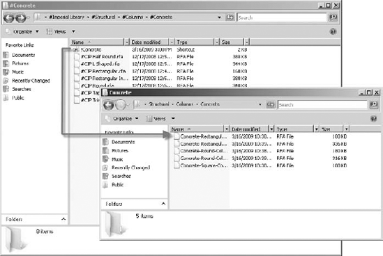
The out-of-the-box content is not under the default directories users place in their Options File Search paths. Instead, placing shortcut links in your directories, such as ..#Column#Concrete, would help isolate and organize any customized RFA files and a shortcut prefixed with a ! to the normal out-of-the-box location ..ColumnConcrete. As a user, when you go to load a concrete column family, you would see #Family folders and a link to the default file location. You can then decide if you need the company standard or want the original files, in which case a single directory click will get you there.
For example, say you need to load a detail component. You fire up the Load dialog box, where you are presented with all #-prefixed family files. More than likely, that is what you want, but on occasion you have not customized your own. So in that directory will be a shortcut link to the same family location under the out-of-the-box folder. The user can then click the link and will be sent into the stock location.
This probably seems confusing, so let's break it down. There are two directory structures, A and B. A has the same organization but contains only custom (#) family files. B, on the other hand, is right out of the box. Within the A structure are shortcut links to the same directory structure location in B. The user's options are all pointed to A directory structures. Take a look at Figure 17.13 for an example of this in use.
If you have used AutoCAD more than casually, you are probably aware of the ACAD.PGP file. You can use this file to define keystroke(s) to invoke a command. For example, you can use this file to specify that rather than using the menu or toolbar button, you simply press L and then Enter to get the Line command.
Revit Structure has similar customization features, albeit in the BIM world. You'll find the file KeyboardShortcuts.TXT alongside the Revit.EXE file. Once you find the file, simply edit it with Notepad. Here's an example entry:
"BM" ribbon: "Home-Structure-Beam"
The "BM" indicates the series of keys to be pressed. That's followed by the exact Ribbon menu path to the command required (in this example, Home Ribbon
Once you open your shortcut file, you will probably notice that most of the commands are not defined. But before you dive in and make a shortcut for every menu command, ask yourself what you need. For each menu item listed, many will be used seldom, if ever. Do you really need a shortcut to something you don't use and therefore won't remember when you actually do need it? You will probably just go up into the Ribbon menu and find it and then run from there. Commands you use every day are the ones you should customize.
To customize a shortcut item, find the command you want, remove the semicolon (;), and type in your one- or two-letter shortcut. For example,
; "" ribbon: "Home-Foundation-Isolated"
would become
"FI" ribbon: "Home-Foundation-Isolated"
So then in Revit Structure, when you type FI, the Foundation Isolated command will start as if you had chosen it from the Ribbon. Nearly every key on the keyboard can be used for a shortcut, even function keys (although the process is little different). Since a function key has a letter and number, they are not quoted. For example, to press F7 and get the Options dialog box, the process would be
F7 ribbon: "Create-Annotate-Spelling"
Finally, you can use the same set of keystrokes (not including a double set of the same letter) for several commands. The first one listed in the KeyboardShortcuts.TXT file will be run first, but you then can use the arrow keys to step through any of the other commands with the same keyboard shortcut definition. If the order in the .TXT file doesn't fit your needs, you can reorder the command so that it does. But rather than moving items to the top, place a semicolon in front of the item being relocated (to shut it off). And then place a working version at the top. This will keep your shortcut file pristine, thus enabling you to make easy upgrades.
In previous Revit Structure versions, the KeyboardShortcuts.TXT file had one line per menu item. With Revit Structure 2010 this has been made more complicated by the introduction of the Ribbon. You may have noticed that many of the tabs contain very similar buttons but are tabbed with different names. Unfortunately this duplication is needed in the KeyboardShortcuts.TXT file as well. So that means if you want to customize a given command, it may need to be customized in several locations. You will need to be very studious in your edits to be sure to find all duplicated command entries.
As you can see, you can do a lot to speed up your work with simple and easy edits to your shortcuts. Although you cannot share a shortcut file on a network, your office should share the customization that you develop, if for no other reason than to let you sit at other stations from time to time to help users understand something and not become frustrated with different command shortcuts.
Now that you have spent considerable time figuring out what your pen weights and line styles should be, you will want to apply them to a model file. You cannot just define these items; you must tell Revit Structure how to use them effectively for your benefit. You will make wholesale assignments and change everything in your model. Then, as needed, make changes at the view level.
Now you have the power to put Revit Structure work for you. You have modified your .INI file, and you have temporary dimension text you can actually read. You have your own custom files available to load before the OOTB files. And you have managed to speed up your user interface by assigning shortcuts to your frequently used commands. After all this, you are ready to see real results in your model by adjusting your object styles and applying visibility/graphic overrides when required. Then we'll check out the concept of color and see what it can do for you.
One of the first things people notice about Revit Structure is that it doesn't have layers. Almost every other CAD software package has layers (or levels)—how can Revit not have layers? Well, in a way it does, but not in the traditional sense. Everything in Revit Structure is an object of some sort. It could be a model object like a column, an annotation object like text, or even imported objects from an AutoCAD drawing file.
You use the Object Styles dialog box to control the model-wide look of everything in Revit Structure. To begin, use the Manage tab
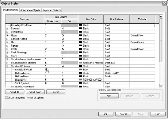
For each object type you have a control for projection lines and, if applicable, cut lines. You also have controls for color, pattern, and, if applicable, material. Each object category will expand into applicable conditions. For example, structural columns have a projection at the base level and then controls for analytical, hidden faces, hidden lines, rigid links, and stick symbols.
Referring back to Figure 17.14 for the Structural Columns category, if shown in a view (not cut), the primary control comes into play. Structural Columns – Projection defines the pen weight. The color on that row sets the visible color, just as the line pattern defines the line type to be used. In the case of columns, since there are many types of columns, you should not set material here as it will be used everywhere unless an instance material has been set.
The other Structural Columns category controls are fairly simple as well. Hidden faces come into play when a face of a column is hidden by itself. An example is a wide-flange column in an elevation turned with the flange facing the view. The line work for the hidden web is a hidden face. A concrete column that stops below a slab in a plan view is a hidden line. The Structural Columns Stick Symbols control applies to steel columns in coarse view detail level.
Each object category has its own set of controls, but many are similar and follow predicable rules. This consistency makes object styles the best way to control your graphic standards for a project model. Earlier in this chapter you learned about line weight and patterns. This is where you should apply those standards first. Whatever changes you make here apply to the entire model and all views that don't have overrides.
Exercise: Seeing the Difference
This exercise shows you the difference between an OOTB model appearance and an adjusted object styles model and how quickly it can be accomplished. Open the Chapter 17 exercise file Model Project.RVT (from the book's companion web page). This model has a basic structure laid out showing a number of object types. We have already created our preferred line patterns and line weights and set the concrete objects to have a solid hatching.
Under the Manage tab, choose the Settings drop-down and click the Object Styles command.
Change the Floors Primary Projection value from pen 2 to pen 7.
Scroll down to Structural Columns and expand the category.
Change the Line Weight Cut value for the primary control from pen 4 to pen 8.
Change the Hidden Lines Projection Line Weight from pen 1 to pen 6. Also change the Line Pattern from Dash to #Hidden
Scroll down more and expand the Structural Framing category.
Change the Structural Framing Girder Projection control from pen 6 to pen 10.
Change the Hidden Lines Projection control from pen 1 to pen 5, and change the Line Pattern from Dash to #Hidden
Change the Structural Framing Joist Projection control from pen 4 to pen 10.
Scroll down to Walls and expand the category.
Change the Walls Primary Projection from pen 2 to pen 7 and Cut from 5 to 8. Change the Walls Hidden Lines Projection value from pen 2 to pen 6. Change the Line Pattern from Dash to #Hidden
Click OK to apply the changes and exit the dialog box.
Now as you can see in the following illustration, all visible model objects changed graphically (hopefully for the better).
The key to making these adjustments is knowing your standards so that you can apply them. Print out a list of your pen weights along with sample sheet of line work so you can see what you are about to assign.
There will come a time when a given view needs a different set of object styles. It could be because the view scale is too large. In such cases you should utilize the differing view scale pen weights, as discussed earlier in this chapter. But what about for specific changes, such as making floors have a surface pattern, or hiding beams, or making some items halftone?
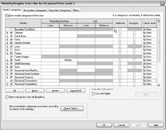
Enter Revit Structure's biggest dialog box, Visibility/Graphic Overrides. As you can see in Figure 17.15, this dialog box looks somewhat intimidating. Not only does it provide controls for the same object options shown in the Object Styles dialog box, but you can even set some object categories to halftone, transparent, and a different view detail level. In addition, using filters you can change only specific objects to look different, based on object type or just those selected objects.
When you go to use the Visibility/Graphic Overrides dialog box, your purpose will probably be to solve some specific problem. Simply make your change and go about your other work. In some cases, the changes will need to be repeated for other views, in which case you can use the View tab
Exercise: Customizing a View
This exercise shows some view customization on the same model used for object styles. Open the Chapter 17 exercise file Visibility Graphics.RVT (from the book's companion web page). You will see that there are some objects added to a filter in order to control them.
Under the View tab click the Visibility/Graphics button to display the Visibility/Graphic Overrides dialog box.
Locate the Floors category, and click in the slot for Projection/Surface Patterns. You will see an Override button; click it.
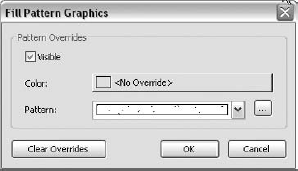
In the Fill Pattern Graphics dialog box, change Pattern to Sand and click OK.
Locate the Structural Columns category and click in the slot for Cut Lines, and then click the Override button.
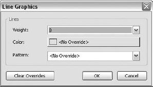
In the Line Graphics dialog box, change the Weight value to 8.
Click the Patterns slot for Structural Columns and change the pattern to Solid Fill.
Click the Filters tab at the top of the Visibility/Graphic Overrides dialog box. Click the Add button.
In the Add Filters dialog box, select Demo from the list and click OK. This then displays the Demo filter with a visibility control like the one for model objects.
Click the Halftone toggle at the end of the line. Click OK to apply and close the Visibility/Graphic Overrides dialog box.
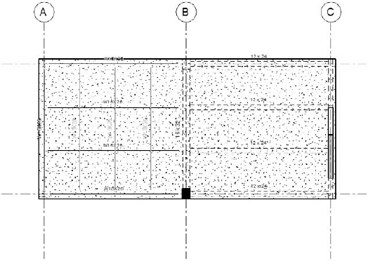
As shown in Figure 17.16, a number of things changed. The floor got a fill pattern applied to entire surface. The columns now have a thinner pen weight, and the concrete column got a solid black fill. In addition, a group of steel beams set for demolition is now halftone.
Overall, you've made quite dramatic differences with fewer than 30 seconds' worth of edits to the Visibility/Graphic Overrides dialog box. You only have to use your imagination to know the boundaries of this capability. In general, making changes this way should be limited to specific views for specific needs. This will ensure that your project standards are model wide, but you'll have a fallback solution when you need standards for specific views.
Many users of Revit Structure products have had previous experience with AutoCAD. Therefore, typically the first emotion when a new user fires up Revit Structure and starts modeling is "I miss color." Revit Structure by default is black and white; all objects are white or black depending on your background screen color. There are few instances of color; levels that have views referencing them have blue target symbols. And sections and elevation views are blue as well. Reference plane lines are green hidden lines.
So why is there no color in Revit? Is black and white so much better than color, and all those AutoCAD users have been doing it wrong for over 20 years? Revit Structure didn't start as an Autodesk-owned application. It was simply Revit and in many ways was competing with Autodesk products. The answer is, Revit Structure was made black and white so that it would not be like AutoCAD. Plain and simple, there was a marketing decision to be different, and the main way to be different was to go no-color.
When you made the transition from AutoCAD to Revit Structure, no doubt you just accepted the black-and-white display. But perhaps you have poked around a little and discovered that color is there—it's just not used. Color is tedious to apply, but once you experiment with it in a model, applying differing color to columns, walls, beams, and the like, it will begin to feel familiar. You will then notice something simple and yet profound: it is easier to tell what you are looking when it is in color!
Interestingly Revit Structure doesn't use color to control pen weight as AutoCAD can, so color inherently won't affect your look unless you plot in color. But imagine you are zoomed into a tight area and you see a hidden line next to another hidden line. Which is a column and which is a beam? Well, you could hover your mouse above that line or select an object to know what it is, but wouldn't it be easier to simply know by its color? You would know visually whether a beam is aligned with the wall, or the wall is aligned with the beam, by the color of each and recognizing what is right and what is wrong.
The focus of this section isn't to propose a color scheme; that is up to you and your fellow modelers. What we suggest is to use color as an advantage in modeling with Revit Structure. It really can help. Just be aware when plotting to assign black and white and not color—unless you want color plots!
- Ascertain what can and cannot be done easily
Standards are there no matter what. What they are and how they are controlled are up to you. Before Revit Structure, users had various files provided with AutoCAD that determined what most of the standards were based on. A standard is many things, but a basic one specifies line weight, pattern, and style. In addition, you have filled patterns that can tone contained areas. You then bring all these definitions together and apply them to object styles, views, and objects to create your drawings.
- Master It
Develop line weights that meet your needs. Create line patterns and styles and then apply them to your model via the Object Styles dialog box. Address annotation and fill standards as well, all matching your required standards.
- Enhance your model through customization
Anyone using Revit Structure deserves to have their tool be as productive as possible. With a little bit of practice, you can take using Revit Structure to a new level.
- Master It
The temporary dimension values in Revit Structure are too small to read, so increase them! Follow that with organizing your firm's library files as well. Then improve usability by using command shortcuts, and take advantage of keyboard input speed.
- Implement model standards and view overrides
Once you have your standards in place, you then have to apply them to your model. There is no need to simply accept what Revit Structure can produce right out of the box.
- Master It
Take your standards and use them to control your model. Then when the need arises, tweak just about anything for a single view at a time. Can you break out of the black-and-white box and think in color again?