
As you have been working through the chapters of this book, you have been learning how to use the basic libraries to obtain your model elements. You go to a library file and load in different types from a family for use in your project, such as a 3 × 6 from the lumber family. But as you gain experience and have to deal with the many objects that occur in a real-world scenario, you quickly find that the built-in libraries do not have everything you need. You'll get into more complex objects such as wood and steel trusses, tapered steel girders, and wood beam nailers, to name just a few. These objects will require more advanced modeling techniques.
This chapter looks at some of these objects that you will undoubtedly encounter and need to model and explores the more advanced methods required to construct them. Integral to this discussion is the notion of pure, solid modeling techniques that enable you to construct modeled objects. Using a combination of solid and void forms that can be extruded, revolved, swept, and blended, you will find that you can create almost any shape imaginable. These tools are located on Ribbon in the Home tab
This is a tall order for one chapter, but you truly do want to move beyond simple techniques in order to unleash the real power of this program. We will break it all down into easy-to-follow steps that you can then apply to your own families when the need arises. The examples that you will learn in this chapter are not perfect, nor are they the final word on how these families might be done. Perhaps if you tinker a bit, you can improve them. The first object you will learn how to construct is a tapered girder family.
In this chapter you will learn to:
Create a parametrically driven tapered steel girder family
Construct an in-place bent beam family
Adapt the steel wide-flange beam family by adding a nailer to its top
Create an elevator pit family that can be dropped into your project
Produce wood and steel truss families using the truss template
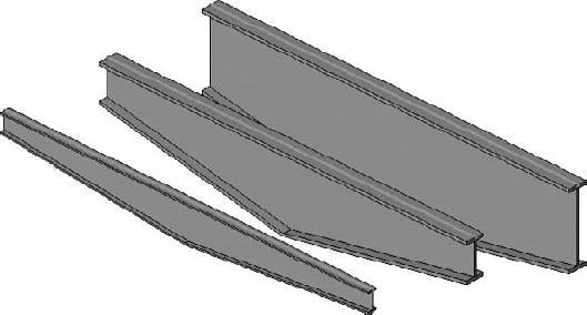
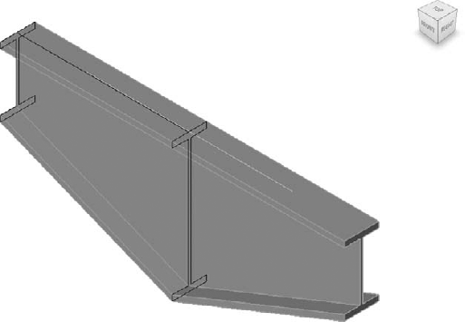
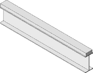
Tapered steel girders are a common element in many buildings but are not available in any Revit Structure family (see Figure 19.1). You will need to prepare your own at some point. Many long-span conditions, such as a gymnasium or a hotel lobby, use this type of girder. A tapered steel girder is one whose center depth is greater than the end depth, or it is flipped upward with the center higher than the endpoints. You could make a single nonparametric tapered girder specifically for your project by making an in-place family (it is nonparametric if it does not flex into different depths). But why not create a family that you can use over and over again and from which you can easily create different mid-span and end-span depths? That is the most efficient approach, though a little more thought provoking and challenging to create. When you are able to develop a truly flexible and reusable family from scratch, you begin to really unlock the power of Revit Structure.
To get the process started, first you will create a new family, and then you will define the basic constraints of the shape. As you learned in the previous chapter on basic family creation, this is done by adding reference planes to which you will lock the girder sketch lines that define its shape. Those reference planes will be dimensioned, and then the dimensions will be enhanced so that they become labels (parameters) whose value may vary. Doing so will allow the shape to flex as you create different types.
Once you've defined the rules that your family will follow, you will create the shape by using the Swept Blend tool to create the tapered form, which will be attached to the reference planes. Finally you will adjust the visibility of the various family components so that they show correctly in coarse or 3D mode.
The first step in making a parametric tapered steel girder family is to open a new family template file and set up some reference planes, so do the following:
Start a new project so that we can use it to test the family as we progress.
Start a new family by choosing New

Select Structural Framing - Beams and Braces for the template, and then click OK.
Once you're in the Family Editor, open the front elevation.
Select and delete the rectangular extrusion that you find there.
Set the Detail Level to Medium so the stick symbol will be hidden.
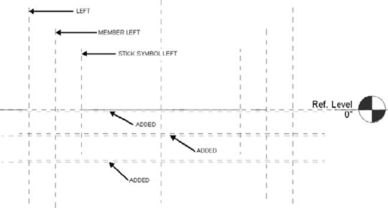
Now you will need to add five horizontal reference planes: one for the top flange of the girder, two for the end-span depth, and two that represent the mid-span girder depth (see Figure 19.2).
On the Datum panel of the Create tab click Reference Plane, then choose Draw Reference Plane from the drop-down list, and draw the five new horizontal reference planes:
Draw one just below Ref. Level (about 1″ down).
Then draw two (about 1″ apart) about 1′ below Ref. Level.
Then draw another two about 2′ below Ref. Level.
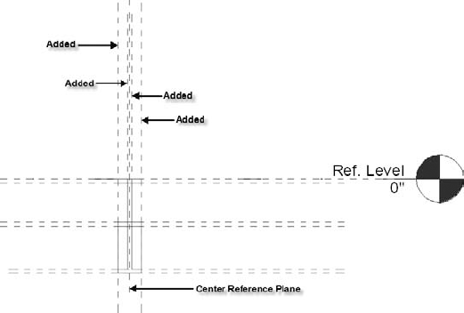
Next go to the right view so that you can add four more vertical reference planes that will represent the flange width and the web thickness.
On the Create tab click Reference Plane, then choose Draw Reference Plane from the drop-down list, and draw four new vertical reference planes like those in Figure 19.3 (note that the girder profile has been ghosted in for the next few figures to make it easier for you to understand what we are doing). Draw two reference planes, at

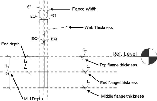
Now that the new reference planes have been added, you will dimension them and apply labels. Your values do not have to match the figure at this time. To dimension the reference planes do the following:
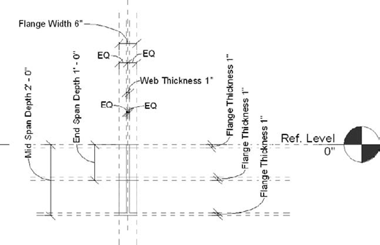
From the Dimension panel of the Detail tab of the Ribbon choose the Aligned Dimension tool. In the right view add seven defining dimensions to the reference lines (see Figure 19.4) for the following:
Now that the reference planes are dimensioned, you will create the labels. You want to make the family parametric so that you can create different family types in your projects. To do this you will alter the dimensions you just added in order to create labels for end-span depth, mid-span depth, flange width, flange thickness, web width, and web thickness.
Select the End Span Depth dimension (1′-0″), right-click, and select Edit Label from the context menu.
Choose <Add Parameter>.
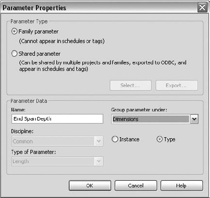
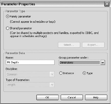
In the Parameter Properties dialog box, name the parameter End Span Depth.
Choose Dimensions as the Group parameter.
Click the Type radio button to make it a Type parameter.
Click OK to complete the label (see Figure 19.5).
Repeat steps 1 through 6, and create the Mid Span Depth, Flange Width, Flange Thickness, and Web Thickness parameters. When completed, your reference planes should look like Figure 19.6.
Now you need to start flexing the labels to test whether the reference lines you have created are working. Remember that you need to constantly test your family by flexing the different dimensions you have established.
Did the bottom two reference lines stretch correctly to the new depth? If not, you need to cancel and check the problem areas. This process can get frustrating, but after awhile you will get the hang of it. Test the other labels in the same way until all are flexing correctly. Once you have the reference lines flexing correctly, open the Ref. Level plan view again.
You now will create the basic geometry of the tapered girder (look back at Figure 19.1). Once you have done that, you are almost finished creating this family. This part of the process will use a Solid Swept Blend to create half of the tapered girder.
Open the Ref. Level plan, if it is not already opened.
From the Forms panel on the Create tab click the Solid tool icon; then choose Swept Blend from the drop-down list.
From the Mode panel on the Swept Blend tab click Sketch Path.
Sketch a horizontal line along the Reference Plane : Center (Front/Back), from the left (leftmost) vertical reference line to the Center (Left/Right) reference line, and lock its ends to them.
Click Finish Path from the Path panel on the Swept Blend
On the Edit panel of the Modify Profile 1 tab click Edit Profile, and then open the right elevation view.
On the Swept Blend
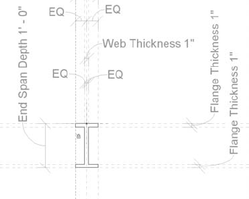
It is very important to make sure that the sketch lines are locked to the reference planes. To do so, follow these steps:
On the Modify tab select the Align feature.
Click a reference line and then the associated sketch line you want to match; then click the padlock icon to lock it.
Do this for all the sketch lines you have created for the end-span depth profile.
Click Finish Profile.
On the Mode panel of the Swept Blend tab, click Modify Profile 2.
On the Edit panel of the Modify Profile 2 tab, click Edit Profile.
On the Swept Blend
Click Finish Profile, and then click Finish Swept Blend.
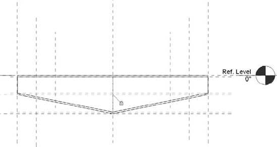
Now go to a 3D view and flex the various values in the Family Types dialog box to test that the shape is stretching as you expect. When you are satisfied that the shape is flexing correctly, go to the front elevation view.
Highlight the swept blend, and mirror it about the vertical center line.
Lock the ends of both swept blends to the vertical center line (see Figure 19.8).
On the Modify tab click Join
With the Align tool lock the ends of the tapered girder again to the left and right vertical reference planes.
It is very important to make sure the sketch lines of the new mirrored solid are locked to the reference planes as well. To do so, use the Align tool. This can get a bit tedious, but pay close attention so that you get all of the lines. When you mirror the girder from one side, you may have to relock to the new reference planes on the other side.
You have now completed the tapered steel girder family (see Figure 19.9) and can make some family types.
Select Types from the Family Properties panel on the Modify tab—or any other tab for that matter.
In the Family Types dialog box choose New.
Name the type 1′ × 2′.
Change the End-Span Depth value to 1′-0″ and the Mid-Span Depth value to 2′-0″.
Click Apply, and confirm that it is flexing okay.
Repeat steps 1 through 3, and create a 2′ × 4′ family type and a 3′ × 5′ family type.
Save the finished tapered girder.
Now you are ready to test the finished tapered girder. It acts like any other beam object, and it also will work with a beam system.
Load the family into a new project.
On the Home tab click Beam.
Choose a tapered girder type, and draw it just as you would any other beam.
Go to a 3D view and check it out.
Real World Scenario: Oh-Oh! We Have a Major Problem Here!
Did you notice one discrepancy in what we have done? Remember how you set the flange thickness dimension and label in the right side view? But in fact the lower flange is sloping. That means the dimension in the right side view is not really the thickness of the lower flange but is a little bigger, as illustrated in the following graphic.

This turns out to be the most difficult and advanced part of creating this family. If you go to the front view and try to add a dimension and label for the sloping bottom flange, you will find that it becomes overconstrained. There is no way around it. So how can we overcome this dilemma? This problem even flummoxed the authors, who then had to contact Revit Structure headquarters for assistance. Coming to our aid was Jack Zhang Lee, one of the family-creation specialists.
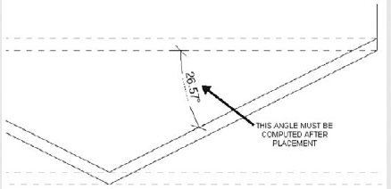
To set the correct flange thickness for the sloped parts of the girder, we need to set the sloped angle beforehand (see the following illustration), so that we can then calculate the flange thickness with that angle. The angle for the tapered girder is a function of the overall length of the girder, so it can be computed only as a resultant value after placing the element. So you must test this family for accuracy in a project, not in the family file.
Yes, you can add formulas to your parameters for just this kind of purpose. Here is how it works.
In the family:
You create a new parameter, namely, Length1, and set Length1 equal to Cut Length.
In the Family Editor, Length1 may not represent the real physical length of the beam, but in the project it does refer to the real physical length of the component. The flange thickness could be calculated precisely in the project with the nested profile employed.
In the project:
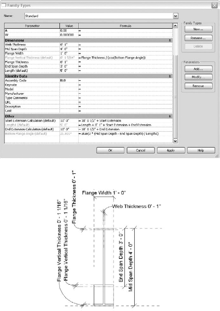
The resultant angle is computed with the following formula (see the two illustrations):
| Bottom Flange Angle = atan(2 *(Mid Span Depth − End Span Depth) / Length1) |
For the beam itself the cut length is computed with the following formula:
| Length1 = Length + 0′ 1″ + Start Extension + End Extension |
Then from that the Flange Vertical Thickness value is computed. Notice how the three parameters are grayed out in the dialog box. That is because they are resultant values that you cannot manually change.
So there you have the answer to a very complex problem. I am sure we could go further in this discussion and keep tweaking the family, but we need to move on to our next advanced structural family. Maybe you can take a crack at it. You may find a better solution. When you get stuck with this sort of thing, it can be very taxing on your sanity! But stick with it, and look around on the Web for help in the AUGI Structural Forum or other such sites. Don't be afraid to ask for help. That's what we did.
We just worked through the process that you use to create a family from scratch. You got off to a good start because you used the template for beams and braces, which saved you a lot of work. You created the proper constraints for the tapered girder geometry. Then you overcame a big problem getting the sloping bottom flange to show the correct thickness. In the next section you will create a single in-place family within an existing project.
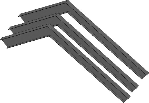
Another common structural item you are bound to need while modeling your building is a bent beam (see Figure 19.10), whether in concrete or steel. You will probably be happy to learn that creating this one is not as involved as creating the tapered girder family. Earlier, in the chapter on framing, you saw that you can create many types of curved beams, but bent beams require a different approach. Since the bent beam is usually an isolated case, you may want to do only a quick model of it directly in your project. This will be accomplished by using the Model In-Place tool. Basically you create a solid sweep and apply a beam profile to it. Then you add a symbolic stick line for coarse detail mode display to finish out the family. But you do not go to the trouble of making the family parametric by creating labels for your dimensions so that it can stretch to many shapes. Let us break down the process and step through its creation.
Here is how the procedure works. First you set up the file and start the in-place family:
Open a new Revit Structure project. It should start with Level 2 open. Change the scale to
= 1′-0″.Draw a single horizontal grid line above the south elevation mark (a named reference plane also works).
On the Model panel of the Home tab, click the lower half of the split button for Component, and then choose Model In-Place from the pull-down list.
Select Structural Framing from the Family Category list, and click OK.
Name the in-place family Bent Beam 1 (you may have others to construct).
Click OK, which puts you in the Family Editor environment but still within the context of your project, and you can now begin constructing the bent beam.
Next you will create a solid sweep. You will need to use a plan view and an elevation view as you construct it. First you will use the south elevation view to draw the path of the bent beam.
On the In-Place Modeling panel of the Model In-Place tab, click Solid
Now double-click the South elevation in the Project Browser.
On the Home tab click Set on the Work Plane panel, and then choose Grid 1 as your active work plane (or select a named reference plane).
On the Sweep tab click the Sketch Path icon on the Mode panel.
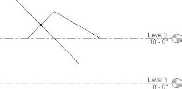
Use the Line tool on the Draw panel to sketch the bent beam path, something like the one shown in Figure 19.11.
On the Path panel click Finish Path to complete the path.
Click Select Profile on the Mode panel of the Sweep tab.
On the Edit panel, use the drop-down list to select a W16X26 from the list of loaded profiles.
On the Options bar change the Angle value to 90 degrees in order to roll the profile into a web vertical position.
Click Finish Sweep, and the basic form is done.
Go to your 3D view and check out your progress.
Now you will apply a material to the bent beam.
Select the bent beam, and click the Element Properties tool on the Element panel on the Model In-Place tab.
Click the Materials parameter field, which then displays the Materials button, the small button with three dots. Click this button to open the Materials dialog box.
Select Metal - Steel - ASTM A36.
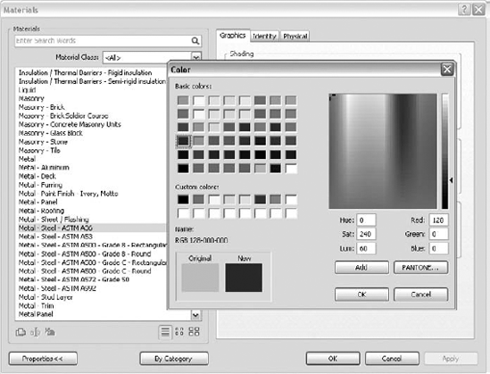
On the right side of the dialog box, click the Shading Swatch button. This displays the Color palette (see Figure 19.12).
Change the color to an RGB (red, green, blue) value of 128, 0, 0, a tone of dark red that makes the steel display more realistically.
Click OK until you exit all the dialog boxes.
You are still in the Model In-Place Family Editor, but now go to the 3D view and check out your results thus far. In the 3D view on the View Control bar, click Model Graphics Style. Select Shading with Edges to get a good display of the bent beam. It is always a good idea to check the 3D view as you work to make sure it looks right.
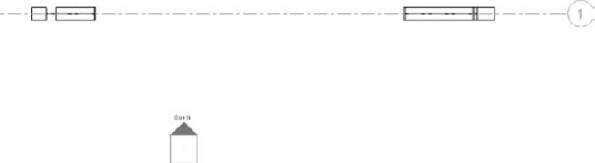
Now you will add a symbolic stick symbol line in plan view. Go to Level 2, and zoom in to the bent beam. You will probably see something like Figure 19.13. Notice that part of the bent beam is above the cut plane of the view and not visible. Adjust the Level 2 View Range until the entire bent beam is visible.
To add the stick symbol to the in-place family, do the following:
Click Symbolic Lines on the In-Place Modeling tab.
Select Stick Symbols [Projection] from the drop-down list on the Element panel.
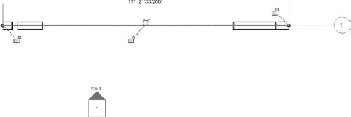
Draw the line along the length of the bent beam, right on the center.
Press the Esc key, and then highlight the stick symbol.
Lock both ends of the stick symbol to the bent beam model (see Figure 19.14). You can use the Align tool for this.
Finally you will adjust the visibility of the family components so they show correctly in different detail modes:
With the stick symbol selected, click the Visibility Settings tool on the Visibility panel.
Uncheck Medium and Fine, as you do not want the stick symbol showing in those detail modes. Click OK to exit.
Select the bent beam sweep, and then click the Visibility Settings tool on the Form panel this time.
Uncheck Coarse, as you do not want the sweep showing in your coarse detail mode views. Click OK to exit.
Click Finish Family.
You have now completed the process of creating an in-place bent beam family. The bent beam can be copied and adapted for other instances as required. But it is important to remember that when in-place families are copied, each instance becomes its own new family. That is a real negative if you want to have many copies in your project, because each copy will have to be individually edited if you need to change the bent beam in any way. So if you think you will have many copies, best practice is to create the family externally and load it in. That type can then be copied, and both the original and the copies need be edited only once.
The next section walks you through creation of a wood nailer on a steel beam family.
So far in this chapter you have created a parametrically driven tapered girder family and an in-place bent beam family. In this section you will alter an existing family by adding a wood nailer. What is that? If you work with wood products much, you will know (see Figure 19.15). Many commercial structures are built using multiple materials such as wood and light steel framing. In order to attach wood members such as floor framing and plywood sheathing to a steel beam, wood members are bolted to the top, and sometimes to the bottom, flange of the beam. These are called beam nailers. Revit Structure does not ship with a family to accommodate this assembly, so you are going to learn how to do it yourself.
Now you could go about this by adding a wood member over a steel member independently of each other, but the process gets quite difficult to control that way. The best approach is to make your own family by adapting the basic wide-flange steel family in order to make your own integrated wood nailer family.
The procedure for creating the basic wood nailer family is as follows. First you need to set up the file:
Open a new default project.
On Level 2 draw a W16X26 beam.
Select the beam, and click Edit Family on the Family panel of the Modify Structural Framing tab.
Click Yes to open the W-Wide Flange beam family for editing.
Immediately save the family using the Save As option. Name it W-Wide Flange with Top Nailer.
Using Windows Explorer, you will next browse to your structural framing library in order to copy the text file associated with the family. Do you know where that is located? If you do not know, you can check under File Locations in the Options dialog box. The default location will be in your Documents and Settings folder. When you find the folder, do the following:
In the Steel Framing library copy the file
W-Wide Flange.txtand save to a new file called:W-Wide Flange with Top Nailer.txt.Go back to the Revit Structure file, and choose the right elevation view.
Zoom in on the top flange of the beam shape.
On the Graphics panel of the View tab, click Thin Lines to make it easier to see the beam lines.
Draw three reference planes above the top flange in order to anchor the three sides of the nailer (see Figure 19.16).
Select the existing vertical Center (Left/Right) reference plane, and click Pin on the Modify Reference Planes tab.

Now you will draw a solid extrusion over the top flange that represents the nailer:
From the Forms panel on the Create tab, click Solid
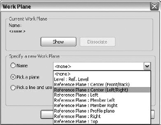
For the reference plane select Reference Plane : Center (Left/Right), as shown in Figure 19.17.
Sketch a rectangle to represent the nailer, and lock the four sides to the reference planes (see Figure 19.18).
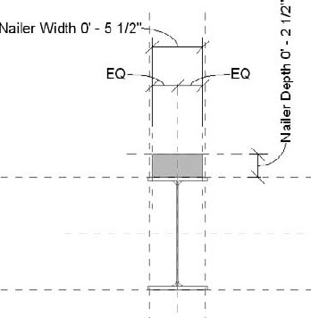
Next you will add dimensions to the reference planes and then create labels that will control the nailer size:
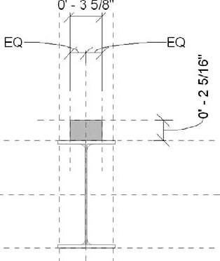
Add dimensions to the added reference planes as shown in Figure 19.19.
Select the Nailer Depth dimension.
Right-click and select Edit Label.
In the Parameter Properties dialog box, name the parameter Nailer Depth.
Group the parameter under Dimensions.
Click the Type radio button to make it a Type parameter.
Click OK to complete the label.
Repeat steps 2 through 8 to create the Nailer Width label.
Now it is time to flex the nailer to make sure it works correctly:
On the Detail tab click Types.
Under Dimensions change the Nailer Depth value to 2.5″ and the Nailer Width value to 5.5″. Those values would be for a standard 3 × 6 profile of a piece of lumber.
Click Apply to demonstrate that the assembly can change to different shapes (see Figure 19.20). If you get a message that the shape is overconstrained, click Remove Constraints.
When you have finished testing, click OK to exit the dialog box.
Now that the nailer profile is completed, the next step is to anchor the extents of it to the ends of the steel beam. Notice that we lock it to the reference plane and not to the actual steel member. That is always the best practice.
Go to the Ref. Level plan view.
On the Modify tab click Align.
Click the long reference plane at the beam end and then the one at the nailer end.
Close the lock, and then do the same for the other end.
Next you need to adjust the visibility of the nailer so that it does not show in coarse detail level:
Select the nailer, and then on the Modify Extrusion tab click the Visibility Settings tool.
Uncheck the Coarse check box, and then click OK to exit.
Finally, you will assign a material to the nailer. Most likely there is no wood material loaded, so you will need to create it:
With the nailer highlighted, click the Element Properties button on the Modify Extrusion tab.
In the Instance Properties dialog box, click into the Value box of the Material parameter, and then click the small button with three dots. This will display the Materials dialog box.
Click the blue icon at the bottom left of the dialog box to create a new material by duplicating the default material.
Call the new material Wood - Dimensional Lumber.
Click the Shading tab, and set the RGB values to 223, 192, 134.
Click OK until you exit all the dialog boxes.
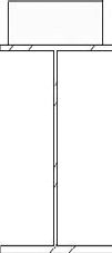
You have now-completed the family. Once again go to the right view, and then change the Model Graphics Style to Shaded with Edges. Does it resemble Figure 19.21? Go to the 3D view, and flex the family with various nailer sizes to make sure everything is working correctly. Now you are ready to load it into your project whenever needed. One nice aspect of this family is that the insertion will be from the top of the nailer, so setting its top in relation to your level can be done quite simply.
The next subject for you to explore is the creation of wood shear walls. Especially in seismic zones, the structural design and documentation of shear walls is essential to master. But what is the best practice in terms of modeling this type of element? It might be a retail store in a mixed-use project, or it might be a student housing project. Your structural model will need interior and exterior shear wall types as well as bearing wall types. Wood projects can be quite a challenge to model because they have many, many pieces, as opposed to a steel or concrete building. So modeling them takes a lot of planning and good modeling techniques.
Of particular importance to this type of wall family is to embed 2D detail components right into the family. You will take a generic wall type and create a 6″ wood shear wall with the required elements. The process you will use to accomplish this is to create a profile family first and embed the 2D components into it. Then you will add that profile to the wall family.
Using detail components in families is an important evolution in your practice, as we briefly discussed in Chapter 9. As you learn more about the family-creation process, you should look for ways to embed 2D components directly into the family.
The goal in doing so is to have the ability to cut a section through your model so that the result is as complete as possible. Having to add lots of 2D lines and detail components to your sections after they are placed in your project adds a lot of extra work, especially when the model starts flexing or you move the wall. The stand-alone 2D components you place in your sections tend not to follow the wall model and must be repositioned, oftentimes more than once. The wood shear wall is a good example of this. The shear wall will have plywood sheathing and top and bottom plates to which the studs are nailed. Why not have everything in one package?
To illustrate this idea look at Figure 19.22. There are four different wall types displayed in section view.
On the left side is a generic 6″ wall that shows no detail of the wall. Lots of work to do there.
Second from the left is a 6″ shear wall in which plywood sheathing has been added and cuts have been made to show the outline of the 3 × 6 nailers. That is a little better.
Third from the left is a 6″ shear wall with plywood sheathing. It also has embedded detail components for the plates and the bolt at the bottom. Better still.
On the far right side you see that a concrete curb has also been added as another option, so you need not draw it separately.
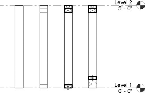
So which wall type would you like to use on your project? Of course, you might ask why we are not modeling all the wall studs and plates. The answer is that we could, but it would be very difficult to accurately place each stud. A worker building such a wall in the field would not find it all that useful to have such a model of framing plans. The important information for the design team is the overall wall length, the sheathing location, and the hold-down anchor locations at the end of the wall and at doorways.
First you will create the profile for the top and bottom plates similar to the way it was done in Chapter 9:
Browse to the Structural Library
On the Family Properties panel of the Create tab click Types.
Click New, and name the new type 3x6.
Set the b dimension to 5-
and the d dimension to 2-; then click OK to exit.On the Detail panel of the Create tab click Detail Component.
Click Yes to load a detail items family.
Choose Detail Components
Select a 3 × 6 component, and click OK to apply it and close the screen.
Rotate the component after placement, and then move it directly over the profile lines.
On the Applications menu choose Save As, and save the new profile with the name
Dimension Lumber-Profile with plate.rfa.Start a new default project, and go to Level 1. Save the project as Wood Shear Wall Example.
Go back to the new profile family, and load it into your new project file.
Now you are ready to begin the process of creating the wood shear wall. Do the following:
In the new project file on the Structure panel of the Home tab, select Structural Wall.
In the Type Selector choose Basic Wall: Generic - 6″.
Click the bottom half of the split button for the Element Properties tool on the Element panel of the Place Structural Wall tab, and then choose Type Properties from the drop-down list
Click Duplicate.
Name the new wall 6″ Wood Shear Wall, and then click OK.
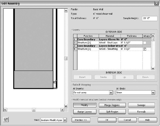
Click Edit in the Structure field, which will display the Edit Assembly dialog box.
Click the Preview button on the bottom left to expand the view.
Change the view to Section: Modify Type Attributes.
Click the Material for Structure [1] area, and select Wood - Stud Layer. Then click OK to close.
Change the thickness to 5
(the actual size of a 3 × 6).Click Insert to add the sheathing layer. Highlight the new layer, and click Up to move it out of the Core Boundary area.
Change the Material value to Wood - Sheathing - Plywood, and then give it a thickness of
.Click Sweeps, and then in the Wall Sweeps dialog box click Add.
Set the following parameters for the sweep (see Figure 19.23):
Profile: Dimension Lumber - Profile Plate: 3 × 6
Material: Wood - Stud Layer
Distance: 1

From: Base
Side: Exterior
Offset: −3
Click OK to complete the addition of the sweep to the wall family.

Next you will unlock the sheathing at the bottom of the wall so it can move independently in the vertical position after placement:
With the Sheathing layer still active click Modify, and then zoom in on the bottom of the wall in the preview. You can use the Steering Wheel tool in the bottom-left corner to navigate the preview window.
Click the bottom line of the sheathing layer until you see the lock; then unlock it (see Figure 19.24).
Next you will add two more profiles at the top of the wall to represent the top plates:
Click Sweeps and then Add.
Set the following parameters for the first top plate sweep:
Set the following parameters for the second top plate sweep:
Profile: Dimension Lumber - Profile Plate: 3 × 6
Material: Wood - Stud Layer
Distance: −3¾″ (note negative value)
From: Top
Side: Exterior
Offset: −3
Click OK to complete the addition of the two top plate sweeps to the wall family.
Click OK successively until you exit all dialog boxes.
Now draw a wall in plan view. Go to a section view, and change the detail mode to Medium. Your wall should look like that in Figure 19.25. Try pulling the sheathing layer up and down to make sure it is free to move. As a further example, you could create another profile family by adding a 2D detail component of a bolt in section to the file you created for the basic stud plate.
There is a lot you can do there, and you will probably have to spend time getting used to this assembly. For now we will turn to creating an elevator pit family from scratch.
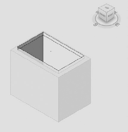
Almost every multistory building is going to have an elevator pit and most likely a sump pit. You will have to show the pit opening and then the pit walls dashed to represent the pit on your floor plan. The pit can appear in different sections you might take for detailing purposes as well. In the 3D modeling world you need to model the pit as one important structural component of the project. If you do not model the pit, you risk losing the integrity of the model as a BIM solution.
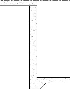
The first and most obvious way to approach the pit construction is to simply add foundation walls and a slab at the bottom of the pit. But this will take some effort in getting all the pieces situated correctly, and display can be messy. The pit slab and walls also generally intersect and form a bearing surface that is a little harder to construct (see Figure 19.26). The inner pit footing line slopes up at an angle connecting to the pit slab. You will need to add a slab edge profile and then join all the geometry to get it looking right.
So instead of using that approach, what if you were to make a parametrically driven elevator pit family that could simply be loaded into your project and dropped onto the floor as a single unit? The 3D pit family would automatically attach to the underside of the floor slab and create the pit opening. The plan view would be exactly and cleanly displayed, and the whole thing could be pushed and pulled into place as one big assembly. For each project you could adapt the pit length, width, and depth dimensions to fit the particular installation in that building. Several types of pits could also be created on one floor.
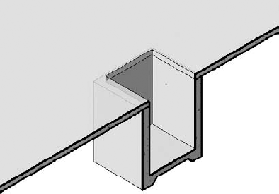
Well, that elevator pit family is exactly what you are going to create in this section of the chapter (see Figure 19.27).
The procedure to create such a pit family can seem quite involved, so we will break it down into parts. You start a new family first and then add reference planes where the walls and pit slab will be located. You add dimensions to the reference planes that you later change to labels. Then you add solid extrusions for the walls and pit slab that are attached to the reference planes. Next you add void forms to make the floor opening and to sculpt the pit slab. Finally you add 2D symbolic lines and set the visibility for different detail levels.
To create an elevator pit family, follow these steps:
Open a new default project.
On the Application menu drop-down click New
For the family template type select Generic Model Floor Based, and then click Open. You then will work on the floor that has already been created in the template. Using the floor-based template means that the pit will be hosted by a floor element.
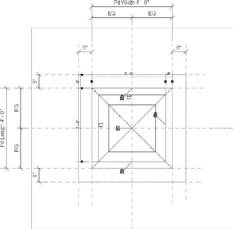
Now you must establish reference planes to which you will attach the walls:
Make sure you are on the Ref. Level plan. Zoom extents (keyboard shortcut ZE) so that you can see the central reference plane axis.
On the Create tab click Reference Plane.
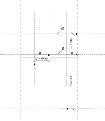
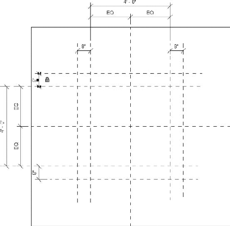
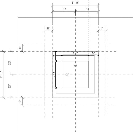
Draw eight reference planes around the central axis to represent the pit wall lines (see Figure 19.28). Do not worry about exact placement or dimension, but make it about 4′-0″ square.
Use Figure 19.28 as a guide to add dimensions to the reference planes. Lock only the four 8″ dimensions.
On the Create tab choose Solid
On the Create Extrusion tab select the Rectangle tool on the Draw panel.
Now draw two rectangles representing the inner and outer faces of the pit, and lock them to the reference plane (see Figure 19.29).
On the Element panel of the Create Extrusion tab choose Extrusion Properties, and make the Extrusion End value equal to −5′-0″. Click OK to close.
Click Finish Extrusion on the Extrusion panel to complete the walls.
Now you will create the pit slab:
On the Create tab click Solid
Draw a rectangle around the inner walls, and lock them to the inner reference planes (see Figure 19.30).
On the Element panel of the Create Extrusion tab, choose Extrusion Properties.
Make the Extrusion End value −5′-0″ and the Extrusion Start value −4′-0″.
Click OK, and then click Finish Sketch to complete the pit slab.
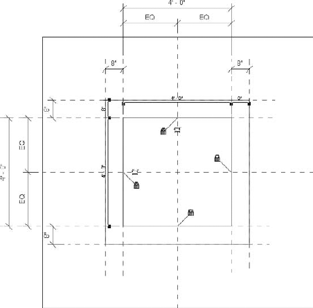
Next you will create the opening in the host floor slab. You should still be in the Ref. Level view:
On the Model panel of the Create tab click Opening. This places you into Sketch mode.
Create a rectangle around the inner walls of the pit and lock the lines.
Click Finish Sketch and there you have it; your basic pit is complete (see Figure 19.31). But it still is not parametric yet, is it? We still have a way to go.
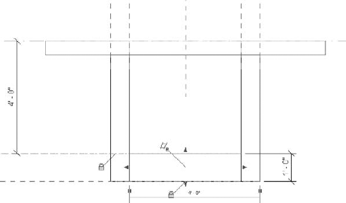
The next step is to add a reference plane and dimensions to control the depth of the pit:
Go to the Front Elevation view.
Select Reference Plane on the Create tab and Pick Existing Line/Edge from the drop-down list.
Click the top of the pit slab line. Stretch the new reference plane line out to the left, and lock the geometry to it.
Repeat steps 2 and 3 for the bottom of the pit slab (see Figure 19.32).
Note that the bottom of the slab and the bottom of wall solid forms must both be locked into the bottom reference plane. If you are having problems selecting either one, press the Tab key until you can select properly.
Add one dimension from the floor line to the top of the pit slab and one for the thickness of the pit slab.
On the Edit Geometry panel of the Modify tab, click Join
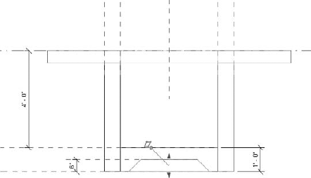
The next step adds a solid void blend to carve out the bottom of the slab so its edges look like Figure 19.34. The point is to make a bearing surface equal to 1′-0″ around the pit. We already have the 8″ pit wall and now must add another 4″.
Go back to the Ref. Level plan view.
On the Forms panel of the Create tab, choose Void
On the Draw panel of the Create Void Blend Base Boundary tab, click the Rectangle tool.
On the Options bar set the Offset dimension equal to −4″. Click the upper left and lower right of the pit opening to create the base of the blend, as shown in Figure 19.33.
Note: If the rectangle starts to appear on the outside of the slab, press the spacebar to make it go inside the walls.
On the Mode panel click Edit Top.
On the Draw panel select the Rectangle tool, and set the offset dimensions to −10″. Click the upper left and lower right of the pit opening to create the top of the blend.
On the Element panel select Blend Properties, and set the First End value at −5′-0″ and the Second End value at −4′-6″. Click OK to exit the dialog box.
Click Finish Blend to complete the void blend.
Go to the front elevation again. Select the void blend, and then align and lock the bottom to the bottom of pit slab reference plane (see Figure 19.34).
Add a reference plane for the top of the void, and lock the top of the blend to it. Make a 6″ dimension, and close the dimension lock.
You have now completed the basic geometry of your elevator pit family. The final step is to make it parametric by changing the dimensions you have created into labels. The labels will contain different values that will represent the various pit types that you will create:
In the front elevation select the Pit Depth dimension, right-click it, and select Edit Label.
Click Add Parameter.
In the Parameter Properties dialog box name the parameter Pit Depth.
Group the parameter under Dimensions.
Click the Type radio button to make it a Type parameter.
Click OK to complete the label (see Figure 19.35).
Now you need to start flexing the pit model to test whether the lines you have created are locked into the reference planes. Remember that you need to constantly test your family by flexing the different dimensions you have established.
Did the model stretch correctly to the new depth? If not, you need to exit and check the problem areas. Most likely something is overconstrained or improperly locked to a reference plane. This can get frustrating, but after awhile you will get the hang of it. Once you have the model flexing correctly, choose the Ref. Level plan view again.
Go to the Ref. Plan view and repeat the process to create new labels for the Pit Length dimension and the Pit Width dimension.
Test them in the same way as you did the Pit Depth parameter to make sure the dimensions are flexing correctly to different sizes.
The final step to complete the elevator pit family is to add symbolic lines for your coarse mode display and to establish the visibility of the various parts of the family. If you use the family the way it is now, the plan view will not display appropriately (see Figure 19.36).
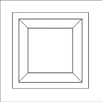
Figure 19.36. The final display must be configured using symbolic lines and visibility settings so it does not look like this.
So do the following:
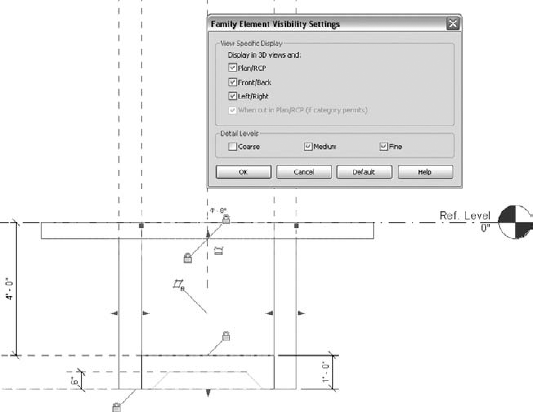
Open the front view.
Select the walls, and then click the Visibility Settings tool on the Form panel of the Modify Extrusion tab.
Uncheck the Coarse detail level, as shown in Figure 19.37. Click OK to exit.
Now do the same for the remaining solid and void forms.
Go back to the Ref. Level plan view.
On the Detail tab click Symbolic Line.
On the Place Symbolic Lines tab, click into the Type Selector and select Generic Models [Projection] from the pull-down list.
On the Visibility panel click the Visibility Settings tool.
Uncheck Medium and Fine so they do not show in those display modes; then click OK to exit the dialog box.
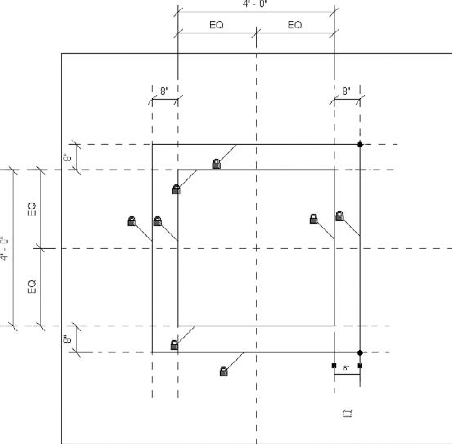
Draw a rectangle at the inner edges of the pit walls, and lock the lines to those reference planes.
Draw a rectangle at the outer edges of the pit walls, and lock the lines to those reference planes.
On the Draw panel using the Generic Models [Projection] line type, click the Line tool, and then draw an X to represent the area of the pit opening.
Now the pit in coarse mode will look like Figure 19.38.
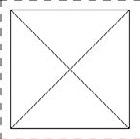
Figure 19.38. The pit plan view after the Visibility settings are completed, showing the symbolic/model lines in coarse mode
There you have it, a finished elevator pit family. It is time to take it for a test run. Start a new project, and on the first level add a 6″ concrete slab. Load the elevator pit family into the file. You will find the family under Generic Models. Drag it out, and drop it onto the floor (see Figure 19.39). Check out the plan view in coarse detail level to make it sure it is displaying correctly. Go to a 3D view, and notice how you can push and pull the pit around the slab. Take note as well how the walls automatically adjust to the floor depth and how the opening is automatically created in the floor slab.
You may now be getting a feel for the power of Revit Structure families and your ability to create your own families for the particular situations your project may demand. The next section focuses on another more advanced item, steel and wood trusses.
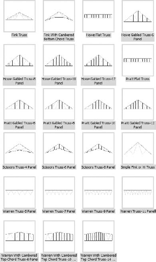
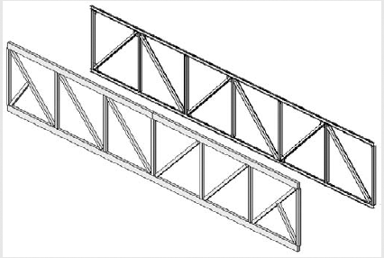
Trusses are one type of structural object that we did not cover in the chapter on structural framing. They tend to require more advanced thinking and planning. While there are many families available for loading into your model, you will come across many conditions that will require you to build your own families. Trusses in Revit Structure are treated as assemblies that are created with numerous pieces. The truss families consist of basic truss forms (see Figure 19.40) and individual elements that can be configured with different structural framing members and whose spacing can be adjusted. The basic forms have a top chord and a bottom chord, as well as vertical and diagonal members.
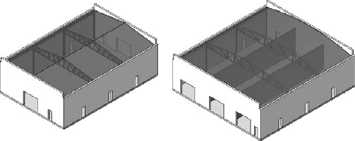
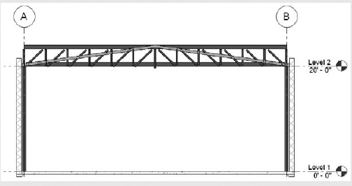
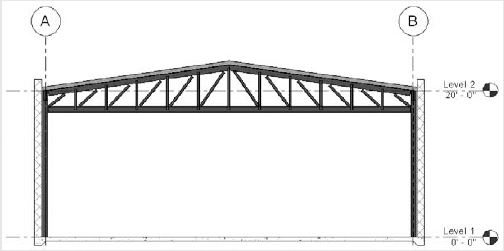
In this section you will look at two warehouse buildings that require the addition of truss framing (see Figure 19.41). For one you will see how to add and create a truss whose top and bottom chord elements are steel WT shapes and whose web members are double angles as a free span over the entire warehouse floor area. This is a very common truss configuration. For the other warehouse you will create a wooden truss whose vertical members must be specifically located over intermediate bearing walls. That will require editing of the truss form itself, and it is the more difficult of the two examples.
Exercise: Adding a Steel Truss to Your Project
In the following exercise you will add free-spanning steel truss to your project and then configure it for a particular condition.
Open
Dataset_1901.rvt(from the book's companion web page atwww.sybex.com/go/masteringrevitstructure2010).In the Project Browser double-click Level 2.
Zoom closer to the section mark along grid line 2.
On Structure panel of the Home tab click Truss.
In the Type Selector choose Howe Flat Truss: Standard if it is not set already.
On the Element panel of the Place Truss tab, click the Element Properties icon; then choose Type Properties from the pull-down list.
Click Duplicate.
Name the new type WT+DBL Angle, and then click OK.
For Top Chord Structural Framing Type select WT-Structural Tee: WT9X25.
For Vertical and Diagonal Webs Structural Framing Types choose LL-Double Angle: 2L4X4X1/2.
For Bottom Chord Structural Framing Type select WT-Structural Tee: WT9X25 and change the Angle parameter to 180.
Click OK until you exit the dialog boxes.
Draw the truss from grid A2 to grid B2.
Now go to section 1, which should look like the following illustration.
Select the truss form. (As you hover over the truss with your mouse, you will see a blue dashed-line representation. Pick that, not any of the individual pieces.)
On the Modify Structural Trusses tab, click the Element Properties button.
In the Instance Properties dialog box, change the Start Level and End Level offsets to −2′−7
.Click OK to exit the dialog box.
Select the truss form, and then on the Modify Truss panel click the Attach/Detach Top Chord tool. Select the sloping roof element. The truss form should realign with the roof.
Select one of the double-angle diagonals or verticals.
Click Element Properties
Click OK until you exit the dialog boxes.
Finally, select all the vertical double-angle web members.
Open the Element Properties dialog box, and change their Start and End Extension values to 4
so they overlap the WTs.Exit the dialog box, and you have completed the basic truss, which should look like the following illustration.
Tinkering with the Truss Model
You can keep tinkering with the individual extensions and truss form to make it even more complete, as in the following illustration. Each member can be individually adjusted. For instance, each diagonal web member could be extended onto the WT web. Then you could cut the end so it is parallel to the chord member by using the Cut Geometry command. You can also add connection plates between the members. If you are working for a structural design firm and spending a lot of time on the plates, that might not make sense. You could document the connections with typical details and simply reference the elevation to those details. On the other hand, if you are working for a structural detailing firm or a contractor, you might want to develop each piece of the truss quite accurately.
But be careful not to overwork the object, and keep in mind the view scale at which you will display the model as well as your final documentation needs. Do not make the model more detailed than necessary. If you do, you will just be burning your project fee with little return to show.
When the built-in libraries and the Truss Wizard cannot work for the condition required in your project, you can build your own truss family. On many projects you must specifically locate the vertical web members of the truss over intermediate supports, so you have to alter the basic spacing of the truss form. Using the truss family template makes the process much easier. The following explanation of this procedure will give you some first-hand experience in making your own truss.
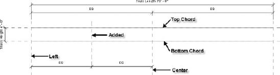
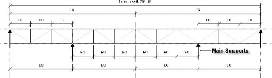
In this second warehouse example, the vertical web members of the wood truss need to located at third points of the truss span because the truss is supported by wood shear walls below. The structural design calls for placing a vertical web member directly over each one. The overall span of the truss is 70′-0″, with the supporting shear walls at 23′-4″ center to center. Develop the truss in the following way:
Open
Dataset_1902.rvt(from the book's companion web page atwww.sybex.com/go/masteringrevitstructure2010).On the Application menu select New
For the family template type select Structural Trusses.
On the Family Properties panel of the Create tab click Types, and then in the Family Types dialog box change the Truss Length parameter to 70′-0″ and the Truss Height parameter to 4′-0″. Click OK to close.
On the Detail panel of the Create tab, select Top Chord.
Sketch a line from the left reference plane to the right reference plane along the top reference plane. Lock the sketch line to the top reference plane.
On the Detail panel select Bottom Chord.
Sketch a line from the left reference plane to the right reference plane along the bottom reference plane. Lock the sketch line to the bottom chord reference plane only.
Now that the top and bottom chords are completed, the web will be constructed starting with the critical vertical web members that go over the walls.
Add a vertical reference plane between the left and center reference planes. These represent the main supports.
Add a dimension string between the three reference planes and make them EQ (see Figure 19.42).
Repeat step 2 for the right side of the truss center line.
On the Detail panel of the Create tab click Web, and then sketch and lock vertical lines at the added reference planes between the top and bottom chords.
Using Figure 19.43 as a guide, add eight other vertical reference planes and then nine vertical lines (do not worry about exact placement). Do not add vertical members at the left and right reference planes.
Using Figure 19.43 as a guide, add dimension strings to the added web members.
Again using Figure 19.43 as a guide, add the diagonal double-angle truss web members between the vertical truss web members.
On the Insert tab on the Load From Library panel, click the Load Framing Family tool
Click Open, and then select a 3 × 6 (which you will use for all the members of the truss), and click OK to load it into your project.
On the Truss Family tab choose Types, and then set the Structural Framing type for the Top, Bottom, Vertical, and Diagonal members to Dimensional Lumber : 3 × 6. Click OK to exit the dialog box.
The truss creation is completed. Now you will save and load the new truss family into your project and do the final configuration after adding it to the model:
Save your new truss family to your project directory with the name Wood Truss Family.
On the Truss Family tab, click Load into Project. (Since the family is already loaded into the project, you will get a warning message asking you if you want to overwrite it, which is what you want to do.)
Back in the building model, use the Project Browser to go to Level 2 if you are not there already.
In the Project Browser find the truss under Families
Draw the truss in plan view from grid A2 to grid B2.
Go to section 1.
Select the truss form, and click the Element Properties button on the Options bar.
In the Instance Properties dialog box, change the Start and End Level Offset value to −2′−0″, and then click OK to exit the dialog box.
Highlight the truss form again.
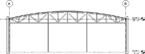
On the Modify truss panel click the Attach/Detach tool.
Select the barrel roof element, and the truss top chord will reconfigure to its radius.
Now the truss is completed and placed into your project. It should look like the one in Figure 19.44. You can further refine the vertical and diagonal member ends as discussed earlier, depending on your requirements. Note that the truss's vertical web members are accurately placed in relation to the walls below it.
So that is the basic story on how to create, place, and configure structural trusses in a project. In the first case you inserted a truss form from the library and adjusted its spacing and members. Then you created your own truss from scratch using the truss template for a very specific web placement.
That completes this chapter on advanced structural families. There is incredible modeling power awaiting you when you reach this skill level. So always keep working on your technique, and try to take it to the next level. You will find that you can save lots of time and effort by taking a more sophisticated approach to your projects, using such families as we have presented here. You surely have some good ideas that will apply to your own work that are not included here.
- Create a parametrically driven tapered steel girder family
In the first section you learned how to develop a new family from scratch using the beam template. You used a blended sweep to create the taper on the lower flange of the girder. You had to introduce a number of new reference planes to which you could then attach the sketch lines of the girder. Adding dimensions between reference planes and making them labels gave you the ability to flex the shape and made the family truly parametric.
- Master It
What does "flexing the model" mean, and why is it important?
- Construct an in-place bent beam family
The bent beam family was created inside the project as an example of an in-place family. You learned how to use a solid sweep form to sketch a path and a steel beam profile along a reference plane in order to create the desired shape.
- Master It
What elements are used to describe the bent beam family?
- Adapt the steel wide-flange beam family by adding a nailer to its top
In this section you adapted the existing wide flange beam family by adding an extrusion onto its top. The extrusion represents the wood nailer and has the ability to flex into different shapes.
- Master It
What are the four main steps necessary to add an extrusion in the shape of a 3 × 6 to the wide-flange beam family?
- Create an elevator pit family that can be dropped into your project
You learned to make an elevator pit family that could be easily inserted into your project. The pit form consists of solid extrusions and void extrusions working together. The whole family is floor based, so it can exist only when associated with a floor object in your model.
- Master It
What is the void blend used for in the elevator pit family?
- Produce wood and steel truss families using the truss template
In the final section you first worked through an exercise in which you inserted a truss from the structural truss library and then reconfigured it to create a steel truss with WT top and bottom chords and double-angle web members.
Then you used the truss template to create a wood truss from scratch so that its vertical web members could be specifically located above supporting walls in a warehouse.
- Master It
After you inserted the wood truss into your building model, how did you make the top chord of the truss follow the barrel-shaped roof?