
The topic of modeling foundations is a broad subject that covers just about any element below or at grade that supports a structure. These elements may or may not be created with the Foundation tools, which in some cases means they are not recognized as being part of the Structural Foundations category. Elements such as walls and slabs on grade may be considered foundations, but to Revit Structure they are typically modeled using the Wall and Floor tools. Other foundation types such as grade beams are modeled as a wall or as a beam depending on your workflow and your desired results. Piers, whether they are concrete or masonry, are modeled using the Structural Column tools and families.
Some forms of foundations are created using tools that we discussed in other chapters. Even though these tools are assigned to other categories, they still serve the purpose of a foundation. To avoid redundancy this chapter focuses on the creation of foundations with the use of the Foundation tools available in Revit Structure. It also mentions how some forms of foundations may be handled without using the tools. Foundations may be the first things to be built during construction, but they tend to be modeled last. This is a direct effect of how Revit automates and keeps track of the relationships between foundations and other elements. Wall foundations need to attach to a wall, and isolated foundations below a column support attach to the column to form a relationship.
Learning the various Foundation tools and how to use them and knowing the best methods to model foundations that don't use these tools will allow you to take full advantage of what Revit Structure has to offer when working with the forms of foundations.
In this chapter you will learn to:
Create and work with isolated foundations
Create and work with wall foundations
Create and work with foundation slabs
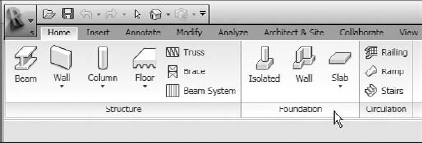
Revit Structure offers tools that allow you to model footings that support columns and piers and to model footing that support walls. These tools available for modeling isolated footings (spread footings), wall footings (strip footings), and foundations slabs (pads) can be found on the Ribbon
Elements placed with these tools are assigned to the Structural Foundations category in the Object styles. Revit Structure deals with these various foundation conditions as system families and component families. The use of system families like wall foundations and foundation slabs allow Revit Structure to automate more of how it interacts with other elements within the model. Using component families for unique foundation conditions gives you tremendous flexibility with regard to creating new shapes and their placement. In some situations such as complicated foundations where you may need to tie into an existing structure or conditions that may be a bit more project specific, you can use a foundation slab or, as a last resort, an in-place Structural Foundation family. The foundation families that are placed with these tools can be found in the Project Browser under the Structural Foundations category, separated into family types, as shown in Figure 8.2.
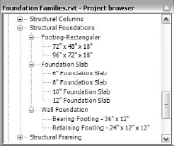
Footing-Rectangular is Revit Structure's default component family. New foundation component families that you create will be added under Structural Foundations. The Isolated Foundation tool is used to place these families into a project. Wall Foundation is a Revit Structure system family that uses the Wall Foundation tool to place it into the family. Foundation Slab is a Revit Structure system family as well. The Foundation Slab tool is used to place this family into a project. Since the wall and slab foundations are system families, you will not be able to create new families for them. However, you will be able to create new types as needed.
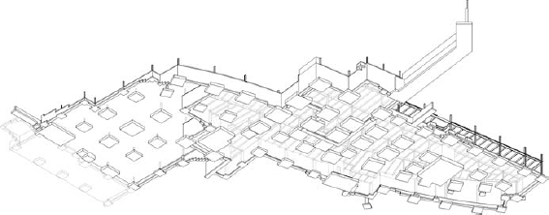
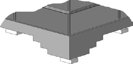
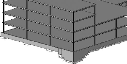
Using all of these tools and family types in conjunction with one another allows you to develop models like the one shown in Figure 8.3.
You use these tools similarly to how you use other tools to model elements within Revit Structure. In order to place a wall footing, you need to have a wall modeled first. Likewise, a wall must exist before you can place a wall opening. The foundation slab works the same way that a floor or roof does except its sloping capabilities are limited. An isolated footing is created the same way as any other component family, such as a structural column or a beam. The differences are that they are organized and managed under the Structural Foundation category and you use slightly different methods for placing them into a project. Once you learn how to use the tools to model elements in Revit Structure, you will find that you can model other elements in a similar manner.
The Isolated Foundation tool has many uses. You need to learn all the various ways it can be placed and how it behaves as it creates relationships with other elements based on its materials, location, and placement methods. It uses component families for elements that are placed, so knowing how to work with these families and how to create new ones for the many conditions you will come across, such as drilled piers, caissons, bell piers, spread footings, and pile caps, is crucial to taking full advantage of the tool. This knowledge will certainly give you an edge up on creating an accurate model, as well as make the documentation process much more efficient.
Revit Structure includes several foundation families in its library located in the Imperial Library
Revit Structure includes a template for you to use when creating new foundation families called Structural Foundation.rft. You can start a new family from this template by choosing the Application menu
This template is already assigned to the Structural Foundations category. Choose the Create tab
You can also see in Figure 8.4 that the Structural Foundations category has a few built-in family parameters that allow the family to behave differently when it is placed into a project depending on these parameters' settings.
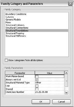
- Work Plane-Based
Enabling the family to be work plane-based allows it to be placed with reference to a work plane (Figure 8.5) rather than a level (Figure 8.6).
- Always Vertical
Enabling the family to be always vertical keeps it vertical when placed. In the Footing-Rectangular footing family, a footing will always be placed with the top and bottom surfaces maintaining a horizontal surface regardless of whether it was placed on a level or a sloped work plane. Disabling this option, as shown in Figure 8.7, allows the footing to be rotated to the level or plane it is being referenced to.
- Structural Material Type
This parameter determines some basic structural behaviors for the foundations when they are placed into a project. It does not specify the material that you use for cut and surface patterns, physical characteristics, and rendering appearance. The main difference between the material types that are available to select is how they autojoin. In an example where a concrete beam frames between two footings, and their structural material type is set to concrete, the intersecting elements will join automatically for cleaning up. For other material types such as steel, wood, and precast concrete, the footings will not autojoin. This parameter also determines whether Revit Structure will generate reinforcement for the family. Families set to Concrete, Precast Concrete, and Other will acquire rebar cover settings in their properties, but steel and wood material types will not.
- Cap
This parameter determines the value for the Elevation at Bottom parameter of an isolated footing after it is placed into a project. If Cap is enabled, the Elevation at Bottom setting will be taken from the Topmost Bottom-Facing Face. If Cap is disabled, the Elevation at Bottom setting will be taken from the Bottommost Bottom-Facing Face (Figure 8.8).
- Shared
Enabling the family to be shared allows Revit Structure to take into account all the nested components when creating a schedule. It also allows the family that is set to be shared to be nested into another family while still existing as a standalone family within your project. An example would be the pile and pile cap families. The HP Shape and Steel Pipe pile families are set to be shared. They are then loaded into the family that contains the cap. These pile families can be maintained separately without opening the pile cap family.
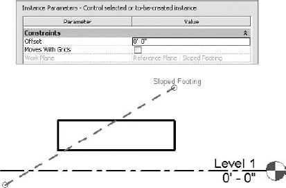
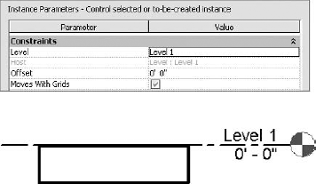
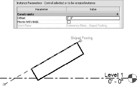
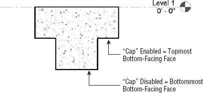
Figure 8.8. The Elevation at Bottom parameter value is determined by the setting for the Cap family parameter.
Real World Scenario: Add Flexibility by Creating a Subcategory
At our firm we assign the families we create to subcategories within their main category. For example, when working with elements that are part of the Structural Foundation category, if we create a drilled pier using a structural foundation, we would assign that family to a subcategory called Drilled Pier. The same goes for a pile cap. It is assigned to a subcategory called Pile Cap. The original out-of-the-box rectangular footing is modified to be assigned to a Footing subcategory.
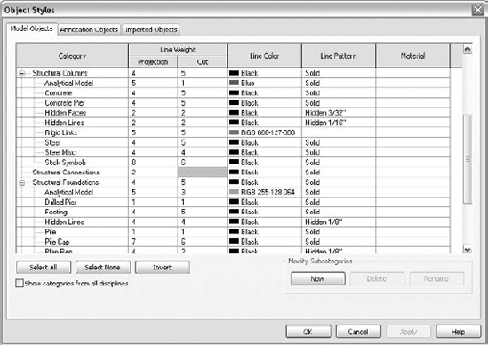
We use the same workflow with other categories such as Structural Framing and Structural Columns. This allows us to have another level of flexibility throughout our model when working with these elements. Is the element a steel, concrete, wood, precast, or light-gauge beam or column? This workflow also gives more flexibility to those who are using our model. They may want to see only certain element types in our model when they are working with it as a link inside their model. They can toggle on/off or change the display of each subcategory individually. Without doing this, one can work with these various elements only by using the main category that the element(s) are assigned to by default.
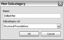
So how do you create subcategories? When in the Family Edit mode, go to the Manage tab
After creating the subcategory, you select all of the geometry that is in your family and open up its Instance Properties dialog box.
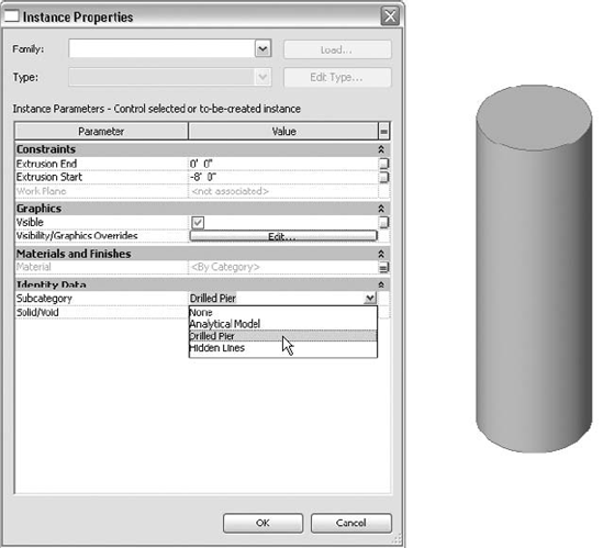
Under Identity Data you will see a parameter called Subcategory. This is where you assign the selected geometry to a subcategory. If you did everything correctly, you will be able to choose your new subcategory from the Value pull-down list.
When incorporating this workflow into your environment, consistency is incredibly important; otherwise, you could end up with several versions of subcategories that refer to the same thing but are named differently.
The Footing-Rectangular family that is provided to you in the Imperial Library includes Length, Width, and Thickness parameters in its properties. Remember what we said previously? Only the Length and Width parameters are built into the family. These parameters are system-based parameters that Revit Structure provides; basically, they are shared parameters. The Thickness parameter was added as a Family parameter that cannot appear in schedules or tags. Nor does it share the thickness parameter name of Foundation Thickness that the system family wall footing uses. What does all of this mean? Well, isolated footings cannot have their thickness value shown in a schedule unless you modify the family to encompass a shared parameter for their thickness. It also means that you cannot place a wall footing and an isolated footing in the same schedule and still get satisfying results. Keep this in mind as you develop your new foundation families.
Now that you have an idea of what determines how a foundation component family behaves and that several foundation types can be placed using these types of families, you are ready to start placing them into your project. Isolated footings behave similarly to other elements in that they will move with grids if you enable them to do so. They will attach themselves to structural columns if the entire extents of the column are within the extents of the isolated foundation. For this reason, before you start placing these elements, you should already have other elements such as grids and columns placed into your model.
You can use views such as structural plan views and 3D views for placing isolated footings, but don't be alarmed when the tool is unavailable when you are in a section view. This is normal behavior because the view's work plane is not such that it allows the isolated foundation to be placed. You must be in a view whose work plane is parallel to a level, like a plan view or a 3D view, which can be set to any work plane.
Since an isolated foundation is a component family, the options for its placement will be more flexible than that of a wall or slab foundation, which are system families. You will be able to reference isolated foundations to a level or reference plane or even host them to a slab. Beyond the option to place them one by one, you can place them by selecting grids or structural columns to ensure more accurate placement.
To begin, select the Isolated tool from the Home tab
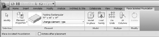
Figure 8.9. The Options bar and contextual tab give you several options for placing an isolated foundation.
The following is an overview of what's available to you for placing isolated foundations into your project:
Ribbon panels
Before placing an isolated foundation, you can select the Element properties of the currently selected isolated foundation to make changes to its properties or duplicate it to make a new type.
From the Type Selector drop-down in the Element panel, select the type of isolated foundation you want to place. If the desired foundation type is not available, you will have to duplicate an existing type or load a new family that includes the foundation type you are looking for.
From the Model panel you can choose Model In-Place, which allows you to create an in-place family rather than placing a component family. This is typically used for project-specific foundations that are more easily modeled in place, so you can see how they relate to elements within the model.
From the Model panel you can choose the Load Family tool to load a new family on the fly. This is for those times when you don't find what you are looking for in the Type Selector; you can load a family while still in the Place Foundation mode. Once the family is loaded, you can start placing it.
Two additional placement options in the Multiple panel are On Grids and At Columns. These are both explained further in "Using the On Grids Option" and Using the At Columns Option."
After an isolated foundation has been placed, you can select the Rotate tool from the Modify panel. Selecting this while still in the Place Foundation mode allows you to rotate the previous footing that was placed. Once this tool is selected, additional options such as Disjoin, Copy, and an Angle designation box will appear on the Options bar.
Options bar
Selecting the Rotate after Placement option automatically puts you in the Rotate command after placement, with the origin point (defined within the family by the intersection of two reference planes) serving as the center of rotation.
If you are in a 3D view when you choose the Isolated tool, the Options bar will also show a Level pull-down. When placing an isolated foundation in a plan view, Revit Structure sets the level of the view as the level for its placement reference as well as its host. When in a 3D view you have to specify on what level to put the isolated foundation. This pull-down will list all of the available levels in your project and is where you specify on what level to put the isolated foundation.
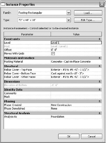
You will find that isolated foundation Instance parameters will vary (similar to other elements of different categories) depending on the structural material type assigned to them in their family as well as how they are placed in the model. Figure 8.10 shows that a typical concrete isolated foundation (Footing-Rectangular family) will have additional Structural parameters for the concrete cover. The concrete cover settings are used to control the location of rebar when placing it into a foundation element. This will be discussed further in Chapter 10. Switching the structural material family parameter (while in the family edit mode) to Steel or Wood will not display this information because those materials do not require a concrete cover. It is rare that you will need to use materials for foundations that are not concrete, which means that you most likely will not have to adjust this setting. However, if you are not seeing the reinforcing information as expected, make sure that the structural material within the family is set correctly.
Isolated foundations will have a level, work plane, or host that they are referenced to depending on how they are placed and how you have set the Family parameters within the family. You can set an Offset value for the location of the isolated foundation from its reference location. If the level, reference plane, or slab moves, the isolated foundation will maintain its offset and move with it.
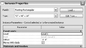
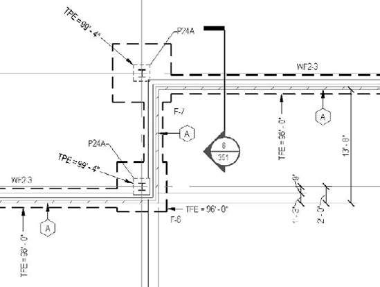
You may have a spread footing that is referenced to Level 1, with an Offset value of −0′-8″, as shown in Figure 8.11. This would place the footing 8″ below Level 1.
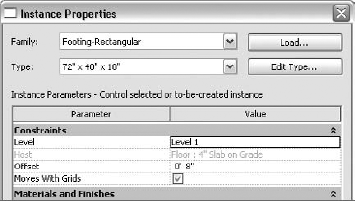
If you had a spread footing that was hosted to a 4″ Slab on Grade floor that was 1′-0″ below Level 1, and the offset value was −0′-8″, the footing would be placed 8″ below the slab, thus making it 1′-8″ below Level 1 (Figure 8.12). Note that in the example where the foundation is hosted to the slab, it can sometimes be tough to determine where the offset is from unless you cut a section and look at the geometry or look closely at the Elevation at Bottom parameter. Both the Level and Host parameters appear in the properties. If the isolated foundation is hosted to an element such as a slab, the offset is referenced from the host, not the level.
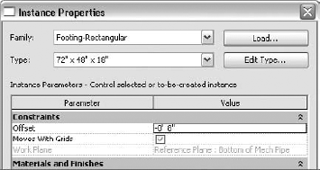
You could also place an isolated foundation with reference to a work plane that was set at a known elevation for some underground mechanical piping. Your footing family could be set so it was work plane–based so it could be placed on a named reference plane. In the example shown in Figure 8.13, the footing is placed on a reference plane named Bottom of Mech Pipe, with an Offset value of −0′-8″. As the reference plane is adjusted to match the bottom of pipe, the footing will maintain its −8″ offset.
Another property worth mentioning is the Moves With Grids parameter. This parameter is either enabled or disabled. If it is enabled and the isolated foundation's origin point is on a grid line, it will move with the grid if that grid is moved. Remember that the origin point is defined by the intersection of two reference planes within the family. Usually these are vertical and horizontal reference planes. If the origin point is touching only one grid instead of a grid intersection, than the isolated foundation will move only with that grid that it is touching. Paying attention to this parameter to ensure that it stays enabled will allow your footings to move with grids when changes are made.
Sure, I Would Love to Be Your Host
When placing an isolated foundation into your project, be cautious of what the foundation takes on as its host. Once the isolated foundation has been placed, you can find this information by selecting it and going to its properties. A Host parameter will be available under the Constraints group. Typically an isolated foundation will host itself to the level that it is being placed on. For example, if you place a footing while in Level 1 view, it will host itself to Level 1. If you place a footing while in Level TFE view, it will host itself to TFE.
What happens if a slab is already placed and within your view range prior to placing the footing? In this case the footing will host itself to the slab instead of the level. Don't believe me; go ahead and try it. It is important to be aware of this behavior. If a footing is to be maintained −1′-0″ below Level 1, then it should be placed so it is hosted to Level 1. If it is hosted to the slab instead, and the slab rises to be +0′-6″, then the footing will move with the slab to maintain its 1′-0″ offset from the slab rather than from Level 1.
In some cases where you want to have that relationship between the footing and the slab, this may be the preferred behavior. If not, you might want to place footings prior to placing slabs or temporarily turn slabs off while placing the footings. If footings are already placed and you need to change their host, all you have to do is select the footing while in a section or elevation view and choose the Pick New Host tool from the Work Plane panel in the contextual Ribbon tab.
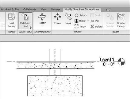
Select either a level or a slab for the new host. Hopefully, at the end of the day, you know who your host is.
When you're placing isolated foundations in Revit Structure, several tools are available that allow you to place them quickly as well as ensure that they are placed properly. Using the default Single Pick option will place single isolated foundations one by one and also allow you to control the rotation of each specific placement. Using the On Grids or At Columns placement option allows you to place several isolated foundations at once while using other elements for their placement location.
The single-pick option is the initial state that Revit Structure puts you in after you select the Isolated Foundation tool. This allows you to place isolated foundations one at a time and adjust settings between each placement.
To use the Single Pick option, follow these steps:
You will typically be placing foundations in a plan view, so activate a lower-level plan view.
On the Home tab

Select the type of isolated foundation you want to place from the Type Selector.
Start placing isolated foundations one by one as they snap to the intersection of gridlines or the centerline of piers and columns. If you are not seeing isolated foundations appear, you may need to adjust your view range settings.
You can rotate isolated foundations while placing them by pressing the spacebar. Each tap of the spacebar rotates the isolated foundation 90 degrees. If the isolated foundation is at the intersection of other elements, it will snap perpendicular to them and use an angle degree that's half the intersection angle. You also have options for rotating after each placement.
This method is useful for placing isolated foundations that are not at the center of other elements or that require a more specific location or rotation. Even after isolated foundations are placed, you can rotate them by selecting one or more of them and pressing the spacebar.
Who Controls the Relationship?
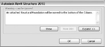
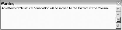
When placing an isolated foundation that is supporting a structural column, you will get a warning telling you that an attached structural foundation will be moved to the bottom of the column.
This is normal behavior. The structural column is creating a relationship with the isolated foundation that you just placed. This relationship occurs whether you like it or not. If a structural column sees an isolated foundation touching its base, it automatically assumes that the isolated foundation wants a relationship. Once this relationship is established, the structural column will attach the isolated foundation to its base and take the isolated foundation wherever it goes. If the structural column's base changes in a vertical direction, the isolated foundation will move with it. The structural column can move in a horizontal direction, and the isolated foundation will maintain its position as long as the structural column stays within the extents of the isolated foundation. The minute that the structural column decides to leave those extents, the isolated foundation will jump back to the insertion point of the structural column.
Keep in mind that if you change the location of the footing instead of the structural column, the column will not change with it to maintain the relationship. It says, "Go ahead and move; I don't care." Their relationship will be broken. Once they come back into contact with each other, their relationship will begin again. In order to maintain the relationship, you must change the base of the structural column. This means that you should drive the location of an isolated foundation through the structural column. When you do this, the isolated foundation will stay attached and automatically move with the base of the structural column. This appears to be a relationship that is mostly controlled by the structural column.
If you use this method for intersection placement or at the origin of other elements, take care to ensure that you are correctly placing the isolated foundation at the correct point rather than at another unexpected point. Keep an eye on the status bar located in the lower-left area of your Revit Structure session dialog box to verify where the isolated foundation is being placed. Setting the Visibility properties of a view to show only grids, structural columns, and foundations may help you select the correct intersection point more easily.
The On Grids option allows you to select groups of grids for placement. Revit Structure will place an isolated foundation on all grid intersections that you select. This can be a quick method for getting isolated foundations into your project. Even if all of the isolated foundations are not supposed to be on a particular grid intersection, it can still be more efficient to place them on grids and relocate or remove those that are off grids afterward (Figure 8.14). This method of placing isolated foundations is similar to placing structural columns; it uses a tool that does the same thing.
For grid intersection placement (On Grids), perform these steps:
You will be placing isolated foundations (footings) in a plan view with grids, so activate a plan view that is set to the level your footings will be referenced to.
On the Home tab
Select the type of isolated foundation you want to place from the Type Selector.
Select the On Grids option from the Multiple panel.
Select those grids that create intersections with a right-to-left crossing window. After they are selected, you should see temporary isolated foundations display at the center of all selected grid intersections.
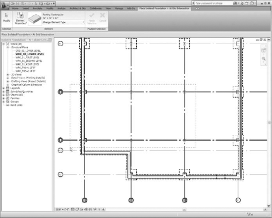
Figure 8.14. Placing isolated foundations with the On Grids option will quickly and accurately place them onto gridline intersections.
Select grids by clicking the gridlines and holding down the Ctrl key to add to your selection or holding down the Shift key to subtract from your selection. You should see isolated foundations appear and disappear at the center of grid intersections as you add and subtract grids from your selection. If you are not seeing isolated foundations appear, you may need to adjust your view range settings.
Once all required grids are selected, be sure to click the Finish Selection button from the Ribbon to accept your isolated foundation placement. Any other action will remove your placements.
You can now delete any unwanted foundations, relocate any if needed, and do any fine-tuning of their rotation.
Using this method will help ensure that all isolated foundations are accurately placed at the exact intersections of the grids. If structural columns were placed the same way, then you can feel confident that your foundations will be centered under them. This will also ensure that the isolated foundations will properly be attached to the grids so that when the grids move, the isolated foundations will move with them.
If the Single Pick or On Grids option is not what you are looking for, than perhaps the At Columns option will do the trick. This option can work best when you are in a 3D view because you can see the location and placement of each isolated foundation as it is placed. Yes, it does say At Columns, but if you have piers that will need footings under them, this will work as well. Remember, a pier, even though it may be considered a foundation, is typically modeled using a structural column.
You can use structural columns and piers that are already modeled in your project to place your isolated foundations. As shown in Figure 8.15, Revit Structure will place an isolated foundation (footing) at the center (origin) of all structural columns or piers that you select. The foundation's vertical location is determined by the level that you assign it to on the Options bar. If this method of placement fits in with your modeling workflow, this can be a quick method of getting columns into your project.
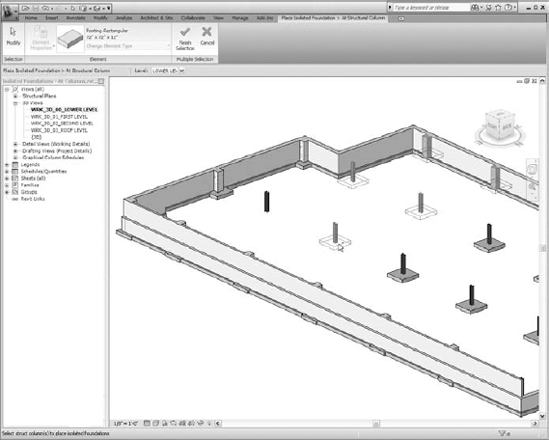
Figure 8.15. When you use the At Columns option, Revit Structure will place an isolated foundation at the center of all structural columns that you select.
For structural column and/or pier placement (At Columns), perform the following steps:
Activate a 3D view that will allow you to easily select the structural columns that require isolated foundations (footings) or a plan view that is set to the level your footings will be referenced to.
On the Home tab
Select the type of isolated foundation you want to place from the Type Selector.
Select the At Columns option from the Multiple panel.
Select groups of columns that require a footing with a right-to-left crossing window. Once they are selected, you should see isolated foundations display centered on all selected structural columns.
Select structural columns individually by clicking a structural column and holding down the Ctrl key to add to your selection or holding down the Shift key to subtract from your selection. You should see isolated foundations appear and disappear at the center of the structural columns as you add and subtract structural columns from your selection.
If you are in a 3D view, make sure that you specify a level for the isolated foundations to be placed on prior to placing them. This is done by using the Level pull-down on the Options bar. If this option is not set properly, you might find that your foundation will be placed in an unexpected location.
Once all required structural columns are selected and your isolated foundations are temporarily in place, be sure to click the Finish Selection button from the Ribbon to accept your isolated foundation placement. Any other action will remove your placements.
There should now be a relationship between the structural columns and the isolated footings. You can now do any fine-tuning of their rotation or change their elevation. Remember, if you will be changing their elevation, you should do so by changing the base elevation of the structural columns. This will change the elevation of the isolated foundations as well.
No matter what type of foundation you decide on modeling as an isolated foundation, you will use these placement methods. By using a component family, you can create all of the various shapes that are needed to model elements that are required for the Foundation category. However, the Isolated Foundation tool cannot be used for modeling all of your foundations. Revit Structure has another tool for modeling other foundations, such as those that are supporting walls like bearings and foundations. The walls that require a footing under them are modeled using Revit Structure's Wall tool, but the foundation below them is modeled using the Wall Foundation tool.
Exercise: Placing Isolated Foundations into a Project
For this exercise you can use the Isolated Foundations.rvt and Isolated Foundation_Complete.rvt files (from the book's companion web page at www.sybex.com/go/masteringrevitstructure2010). You will go through the steps of placing isolated foundations into your project.
Open the
Isolated Foundations.rvtfile.Open the Level 1 Structural Plan view.
Choose the Home tab
Initially you are in Single Pick placement mode. Set the Type Selector so you will be placing a Footing-Rectangular 72″ × 48″ × 18″.
Place a column footing at Grids 2-B and 2-C by hovering over the column/grid intersection. Verify in the status bar that you are snapping to the correct grid intersection. The isolated foundation will snap to various points; when it is in the correct location, pick with your mouse to place it.
You will see a warning dialog box that says the structural foundation will be moved to the bottom of the column. This is fine because the base of the column is 8″ below Level 1 and the footing is being placed at Level 1. Revit Structural recognizes the relationship that a column and footing have and automatically attaches the footing to the base of the column.
After these two footings are placed, select one of the footings and right-click to choose Element Properties from the shortcut menu.
Review the properties of the column footing. Note that Its Level is set to Level 1 and its Host is Floor: SOG 4″. It also is has an Offset of −0′-8″. Since the host is the slab, if for any reason the slab were to change elevation, the footing would maintain the 8″ offset from the slab, not the level.
Repeat steps 3 through 6 except place the column footing at Grid 3-B.
While reviewing the properties of this column footing, note that Its Level is set to Level 1 and its Host is Level: Level 1. It also is has an Offset of −0′-8″. Since the Host is set to Level 1, the column footing will maintain the 8″ offset from Level 1, not the floor.
Open the TFE Structural Plan view. We are using this view so our footings will reference the TFE level. Placing them in the Level 1 structural plan view would reference them to Level 1 and attach them to the base of the steel columns instead of the concrete piers.
Choose the Home tab
Select the On Grids tool from the Multiple panel on the Place Isolated Foundation contextual tab.
Verify that the Type Selector is set to use Footing-Rectangular 72″ × 48″ × 18″.
Create a window selection by using a right-to-left crossing window to select all of the grids that are on the east wing.
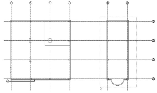
Once the grids are selected, you will see temporary column footings placed at any intersection that the grids create. Choose Finish Selection from the Place Isolated Foundation > At Grid Intersection contextual tab to accept their location.
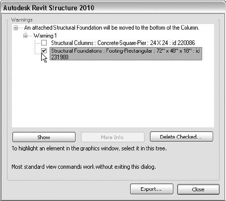
Wait, did you see the warning dialog box? Selecting the Expand Warning Dialog button at the right of the warning will expand the warning to give you more information about the column footing that was moved. Checking the elements in question will highlight them in the drawing area. In this case the column footing is at grid intersection 6-C. The base of the concrete is −2′-0″ below the TFE level, so Revit Structure automatically moves it to the bottom of the concrete pier, giving it a −2′-0″ offset value from TFE level.
Choose Modify from the same tab or press Esc on the keyboard to close the Place Isolated Foundation contextual tab.
Review the properties of the column footings—the one that was moved to the bottom and one of the others.
At-Columns Placement
Open the 3D_Level - Slice view.
Choose the Home tab
Select the At Columns tool from the Multiple panel on the Place Isolated Foundation contextual tab.
Verify that the Type Selector is set to use Footing-Rectangular 72″ × 48″ × 18″.
On the Options bar set the Level to TFE. This sets the level that the column footing is referenced to.
Rotate the 3D view to a location where you can select the concrete piers on which to place the column footings. For now just select the concrete piers individually by holding down the Ctrl key on the keyboard and selecting each one you want to add to your selection set. Remember, we talked about several other ways to select the columns; you can try these other methods as well.
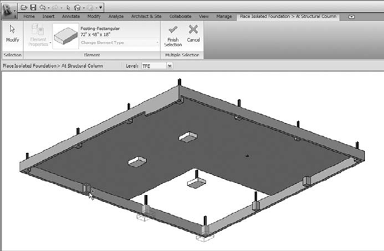
When your selections are complete, choose Finish Selection from the Place Isolated Foundation > At Structural Column contextual tab.
Choose Modify from the same tab or press Esc on the keyboard to close the Place Isolated Foundation contextual tab.
Review the properties of one of the column footings. You will see that it is referenced to TFE and its Host is Level: TFE. It does not have an offset because the base of the concrete pier is at the TFE level. If the base was offset from the level, you would get a warning dialog saying that your structural foundation will be moved to the bottom of the column. In this case it would be a concrete pier. The offset value would be whatever the base offset is for the concrete pier.
Continue using the methods above to finish placing the isolated foundations. Compare your work with the sample file Isolated Foundations_Complete.rvt. Naturally, every project will present different situations, and depending on what those situations are, you will use what you think is the best tool for the job.
Unlike an isolated foundation, the wall foundation (wall/strip footing) is a system family that is predefined in Revit Structure, which is much different than the isolated foundation component family. We start this section with an overview of all the properties and behaviors that can be assigned to a wall foundation as well as how you work with them as you develop your model. Before you start to place them into your project, you should have a good understanding of how they work. We will discuss the actual procedures for placing them in your project in a later section called "Adding Wall Foundations to Your Project."
In order to place a wall foundation you must have a wall in your model for the foundation to attach (hosted by) to. Without a wall you will not be able to place the wall foundation. With that said, if you delete a wall that has a wall foundation beneath it, you delete the wall foundation as well. Since the wall foundation is predefined in Revit Structure, you do not have the flexibility to create shapes that do not already exist. But then again, a wall foundation really only has one shape, a rectangle, as shown in Figure 8.16.
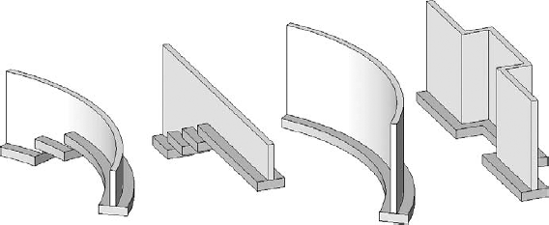
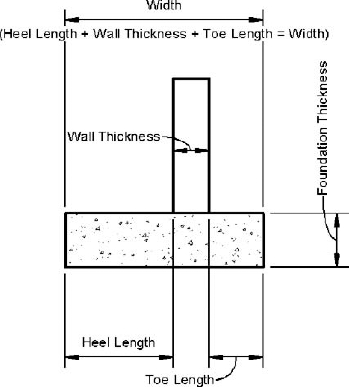
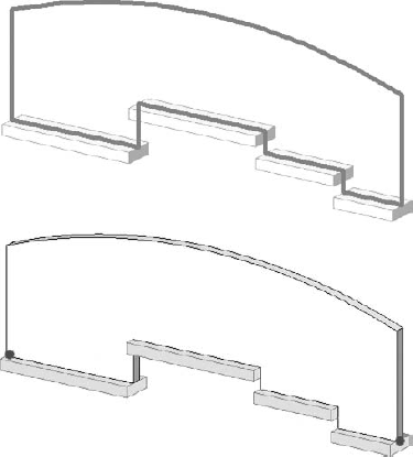
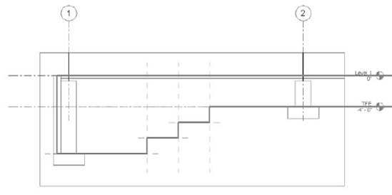
The parameters that you will need to adjust when working with a wall foundation are width, foundation thickness, location on the wall they are supporting, and length. The size of a foundation is set in its Type properties, so each different size you need, with the exception of length, will have to be a new type. Its elevation (top of footing) and length are determined by the location of the wall's base and length. Figure 8.17 shows several wall conditions that indicate how the wall foundation attaches (host) to a wall and maintains its position to the wall location.
If a wall is split to form another section of wall, then the footing will be split as well. Each segment or each individual wall requires its own wall foundation. Keep this in mind when you start changing wall footing sizes. An entire length of a wall may call for the same footing sizes, but as you continue to model your foundations, you may have had to split walls (which also splits the footings) to adjust the elevation of the wall's base for stepped foundations (footings) or to change the wall type to a different thickness. This would mean that you would have several footings to adjust for that length of the wall.
Other properties allow you to define the location of the wall footing to control whether it is centered on the wall or offset. The properties that become available for you to control this behavior depend on the Structural Usage setting that is specified in the wall foundation's Type properties: Bearing or Retaining. Depending on which one is assigned, the wall foundation will take on behavior that allows you to control the location (horizontal offset) of the wall foundation from the wall it is attaching to.
The default project template that Revit Structure uses includes two wall foundation types. They are Bearing Footing - 36″ × 12″ and Retaining Footing - 24″ × 12″ × 12″. The difference between the two is their Structural Usage setting. One is set to Bearing and the other is set to Retaining. The naming of these footings is such that they depict the structural usage they are set to, as well as what the values are for the properties that control their shape. Keeping the structural usage notation in the name is a good idea to help you keep track of what type the footing is, but you can choose your own naming convention for the size representation if desired. This is just Revit Structure's suggestion.
So what is the difference between a bearing and a retaining footing? The big difference is in their Type properties, which contain the parameters to control their size and location as they relate to a wall. You will want to get familiar with these properties to know how each parameter will affect the footing when it is changed.
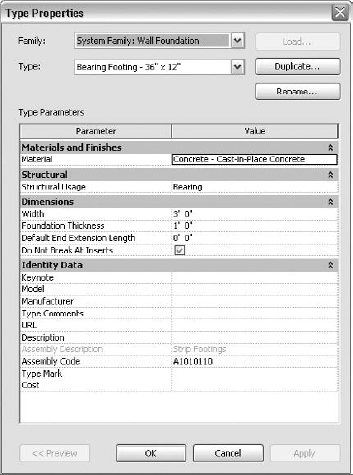
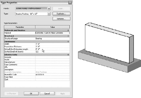
A bearing footing is defined by the Width, Foundation Thickness, and Default End Extension Length settings. Figure 8.18 shows the Type Properties dialog box of a wall footing whose Structural Usage setting is set to Bearing.
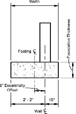
When a bearing footing is placed under a wall, it is centered by default. To offset a bearing footing, you specify an Eccentricity increment value in the Instance properties of the wall foundation (Figure 8.19).
The current version of Revit Structure does not allow you to specify an Eccentricity value that will align the edge of the bearing footing with the edge of the wall. The maximum offset value that you can achieve is determined by the thickness of the wall. So you may or may not be able to get things to go in your favor when offsetting the bearing footing. This is a known issue with the initial version of Revit Structure 2010. If you are looking to model a wall foundation that has a zero-lot line footing where this type of footing placement is desired, you will have to use the Retaining Structural Usage setting and set the Heel and Toe offset values accordingly.
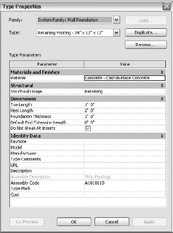
Retaining Footings have additional properties that bearing footings do not have. They are defined by the Heel Length, Toe Length, Foundation Thickness, and Default End Extension Length settings. Figure 8.20 shows the Type properties of a wall footing whose Structural Usage setting is set to Retaining.
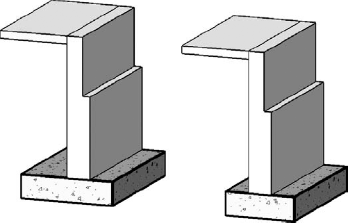
One of the most common mistakes while attempting to place a bearing footing can be unknowingly placing a retaining footing instead, or vice versa. It is easy to do because they have the same rectangular shape, but how they center themselves on the wall is much different (Figure 8.21). The two types are similar but will obviously affect the model in different ways.
The Structural Usage setting offers various dimensional parameters to control the location of the wall foundation with relationship to the wall's width, but what about controlling it along the wall's length? When you select a wall to place a wall foundation, the foundation will automatically adjust its length to the wall's length. If a wall is 10′-0″ long, then your wall foundation will be 10′-0″ long.
In a situation such as a wall thickness bumpout, termination of a wall segment, or a footing extension into an opening cutout, you may need to extend the footing past the wall end to get the proper footing extension from the end and sides of the wall. There is an additional Type parameter for the wall foundation regardless of it structural usage called Default End Extension Length that allows you to control how Revit Structure behaves for these situations. In addition, there are controls on the wall foundation that allow you to adjust their end extensions so they are not always the same length as the wall.
Earlier versions of Revit Structure made the task of extending a wall footing past the ends of a wall difficult. Your options were to just leave it the way it was and say it was a Revit thing, use an in-place family or component family that was placed at the end of the wall or footing, or use foundation slabs to model slivers of slabs to indicated the footing extension. The end extension enhancement that was added in the previous release makes this much simpler and easy to work with as well.
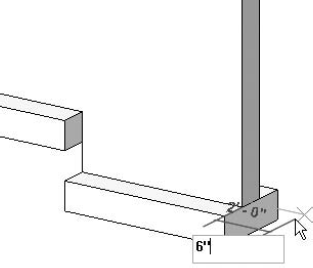
After selecting a wall footing, you will see blue-filled dot controls display at its ends. You can select these controls and drag the end of the footing to a new extension length as long as it extends past the end of the wall. Revit Structure does not allow you to drag the control to the inside portions of the wall. It will let you drag the control, but when you release it, it will snap back to its previous location. You can adjust wall-footing extensions from any view; a 3D view is a great view to use, and it allows you to see exactly what is happening from all angles. Figure 8.22 shows the basic steps involved when adjusting a wall foundation's end extensions.
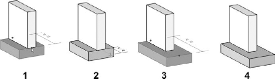
Figure 8.22. After selecting a wall foundation, choose the blue-filled dot control to adjust its end extension past the end of the wall.
Use Those Temporary Dimensions
When selecting a wall foundation to adjust its end extension, you can use the temporary dimensions to accurately create the extension length. After selecting the blue-filled dot control and dragging it in the direction of the extension, start typing in the dimension. The temporary dimension with blue text that appears from the end of the wall to the end of the wall foundation will allow you to enter the dimension for the extension. When you've added your dimension, press Enter, and the wall foundation will adjust to that dimension length.
We also need to discuss the Default End Extension Length parameter located in the Type properties of a wall foundation. This parameter works in conjunction with the extension of the footing that we just talked about. It allows you to set a default dimension that the footing will use to automatically extend the footing past the ends of a wall that it is attaching to when it is placed, thus minimizing the task of having to adjust every extension manually. The default value is 0. Figure 8.23 shows this parameter set to 0′-6″. After placement, each instance of the wall foundation can be modified to have a different end extension length by adjusting the end extension controls.
Take some time to learn how this setting behaves. If several footings have been placed and this value changes, those types will change to the new setting if they have not been previously overridden by dragging the blue extension control. For example, if value of the Default End Extension Length parameter for a specific wall foundation type is set to 0′-8″, and several of these types have been placed throughout your model, all of their extension lengths will be set to 0′-8″. You may have a few locations that need to be adjusted to something other than this dimension, so you do so manually by adjusting the end extension control. If somewhere down the road this value gets changed or set back to 0, all of the extensions will be reset to that new value. Those that you manually adjusted will remain the same.
Yes, Only Two Wall Foundation Extension Controls per Wall
When you edit the profile of wall to set its base location, a wall foundation that you are placing under it will split at each base offset location. However, you will only be able to adjust the extension ends of the wall foundation at the ends of the wall. Extension controls (blue dots) will not be available at the intermittent offset locations.
In some cases this may be thought of as good behavior, but if you place several wall foundations throughout a project, it can become difficult to keep track of which ones have been overridden as well as difficult to predict which ones are going to change. We recommend that you keep the Default End Extension Length value set to 0 and manually adjust the extensions as needed unless you have specific requirements that make sense to set the value to a known dimension. The key thing is to know what this parameter does and how it behaves so you can use it and work with it inside your project in the way that makes your modeling the most efficient.
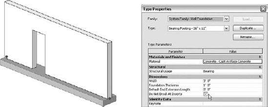
When an opening is made in a wall such as a door, and it cuts the bottom of the wall, you might want the wall foundation to stop and slightly extend past the jambs of the opening, or you might want the wall foundation to run straight through. This is where the Do Not Break At Inserts Type parameter comes in handy. The downside of taking advantage of this setting is that it will work only if you create the opening in the wall a certain way.
How you go about putting openings into your walls will skew your decision one way or another to use this setting. Its intended use is to break a wall footing at an opening insert if the opening cuts the bottom of the wall. The opening is the insert. This is a fairly common scenario in any type of building that you will be modeling. An interior bearing wall may extend 8″ below the slab. The bottom of the opening would extend to the top of the footing, cutting out the bottom of the wall. The slab on grade would then be thickened to tie into the footing.
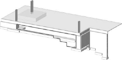
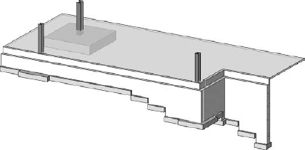
Enabling this parameter, as shown in Figure 8.24, keeps the wall foundation running continuously through the opening insert.
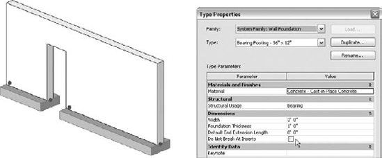
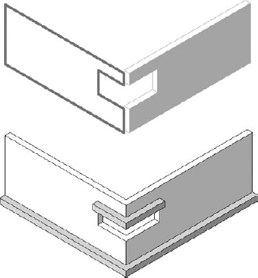
Disabling this parameter, as shown in Figure 8.25, breaks the wall foundation at the jambs of the opening, while giving you additional extension controls at the ends of each break. Even though the wall foundation appears to be broken and behaves as two separate foundations, it is still one wall foundation that is attached to the entire wall length. Deleting one side of the wall footing or the wall will delete both wall foundations.
Unfortunately, this parameter and the behavior it creates work only for openings that have been created with the window and door families (.rfa). These families can be found by going to the Imperial Library
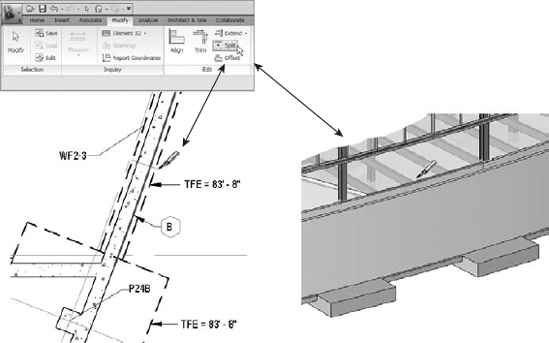
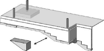
Tools that you may be using to create openings in your walls such as the Wall Opening tool or the Edit Profile tool shown in Figure 8.26 are not recognized as an opening insert; therefore, the wall foundation will not break or be continuous as you would expect in these locations.
All this talk about how to adjust the horizontal location of a wall foundation with respect to the wall, and extending its ends past the end of the wall, or that a wall foundation is attached to the bottom of the wall, but nothing has been said about creating a stepped foundation (stepped footing). What is the best way to model and show a stepped footing? There are a couple of methods that you can use to do this.
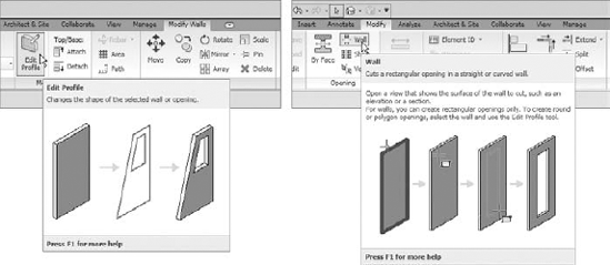
Figure 8.26. The Do Not Break At Inserts parameter is not recognized by the Edit Profile and Wall Opening tools.
Adjusting a View for Heavy Hidden Line Footing Display
If you desire to have all structural foundations display with a Heavy Hidden line style, then you will need to apply overrides to your view.
The first view adjustment you will need to make is in the View Range settings of the view. To access the View Range dialog box, choose the View Tab
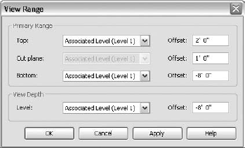
Be sure to set the Bottom Offset depth and the View Depth Level to values that are below the bottom of the lowest footing in your project. For most foundations without basements or many unexcavated areas, the Bottom and View Depth values could be set to Unlimited. Both adjustment methods allow all foundations under slabs or other elements to be displayed with the Hidden Line subcategory for structural foundations and those not under slabs or other elements to be displayed with the Projection Line settings for structural foundations. Those footings where the bottom plane of the view is cutting through or above will not be displayed on the Hidden Lines subcategory; rather they will be consider a Beyond line style, which is a solid line pattern.
The second view adjustment you will have to make is in the Visibility/Graphic Overrides dialog box of the view. To access this dialog box, choose the View tab
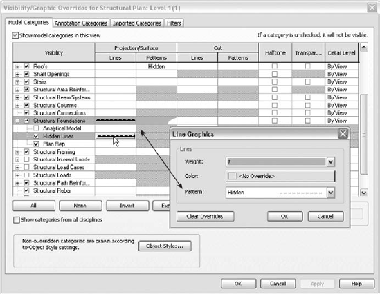
Apply Projection/Surface Lines overrides to both the Structural Foundations category and the Hidden Lines subcategory. Choose the Lines Weight and Pattern that match your standards for drawing display. If the view range of the view is set as discussed previously, those foundations that are below a slab or other elements should be assigned to the Hidden Lines subcategory, and those that are not (for instance, a perimeter wall foundation) should be assigned to the Structural Foundations category. After you apply the overrides, your foundation should appear with a Heavy Hidden line style.
If you've created additional isolated foundations and have assigned them to subcategories within the properties of the family, you will need to adjust their Projection/Surface Lines settings as well. When everything is set and you are happy with the display, create a view template that can be applied to other foundation plan views that require the same overrides.
Whether you model a wall as a curve or a straight segment can determine the method you use to create a stepped footing. In the end you will need to decide for yourself which is the best way. If it is a curved wall segment, you are stuck with one option; with a straight segment you have a couple of options. Either way, you will end up with the same results as far as how it will look in your model.
Let's start by looking at what we think is the obvious approach of creating a stepped footing, which works no matter how you model your walls. You split the wall by using Revit Structure's Split tool. This can be done before or after a wall foundation is placed. Normally when you are modeling a foundation wall for the initial stages of a project, you don't know where grade will be; therefore, you do not know where steps are required in the footing. Keeping this in mind, you model the wall at one elevation without worrying about where the steps occur. Eventually this information becomes available, and you revise the model to show steps where they are required. This is why we mention the Split tool; it's a rare occasion when you know where to step the wall when you are modeling it the first time. To access this tool choose the Modify tab
The Split tool can be used in just about any view except a schedule view; use whichever is most convenient and/or makes it easiest for you to perform the split. This method works for creating a stepped footing in both curved and straight segmented walls. Once the wall is split, you can adjust its bottom extents to the desired top of footing elevation. Sometimes splitting the walls can be a bit too time consuming and may seem like a grueling task to do. This really depends on the number of stepped footings that occur and how you have modeled your walls. Some complicated stacked walls may be difficult to split. They have more individual walls to manage, and you must be sure that they all join properly. In these cases, editing the profile of the wall may be a better road to take.
Editing the profile of the wall to create a stepped footing works well for a straight segment wall, but unfortunately it does not work on a curved wall segment. When you edit the profile of a wall, you enter into a Sketch mode where you change the extents of the wall. Revit Structure is unable to take a curved wall and flatten it out as if it were a straight wall. Because of this, Revit Structure does not know where to show the boundaries of the wall. Therefore, the Edit Profile tool for a wall will not be accessible for a wall that is modeled in this manner. Your only option is to split the wall. Remember, a wall footing hosts to the bottom extents of a wall, so if those extents change, the footing will change as well.
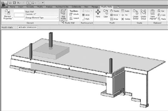
To start this process, cut a section/elevation that is looking perpendicular at the wall that you will be stepping; a 3D view will work as well. You decide which type of view works best. When you are in a view that allows you to look perpendicular to the wall, select the wall to edit and choose the Modify Walls contextual tab
If you are modifying a wall that has not yet been modified with this tool, you will see only the Edit Profile tool while the wall is selected. You will also see only magenta sketch lines (Revit Structure's default sketch line color) at the boundaries of the wall when you are in the Sketch mode. If you select a wall that already has its profile edited, you will see an additional tool in the Modify Walls contextual tab called Reset Profile (Figure 8.29). A wall that has its profile edited will continue to show its original boundary locations with a dashed line pattern while in the Sketch mode. This allows you to see the original extents of the wall prior to it being modified. Selecting the Reset Profile tool will reset the profile back to the dashed line pattern location, removing all profile edits you have made.
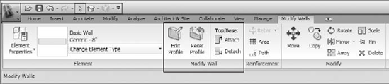
Figure 8.29. The Edit Profile and Reset Profile tools are available in the Modify Wall contextual tab
After you select the Edit Profile tool, the Modify Walls
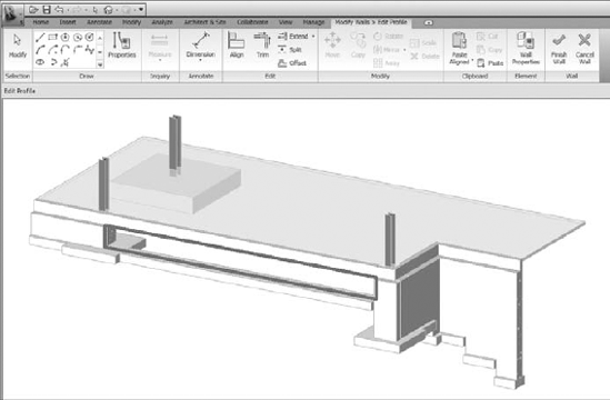
Using the tools in the contextual tab you can add additional sketch lines, split sketch lines, and trim sketch lines to form a closed-loop boundary, as shown in Figure 8.31.
Editing the Wall Profile Might Produce Unexpected Results
You can edit the profile of a wall to create steps in your footings as well as openings and other wall shape configurations. But when you do this, the wall foundation may not always perform as expected. If the profile sketch is such that it creates two wall bases, as in the example shown below at a corner window, the wall foundation will attach to both the base of the wall and the window head.
Revit Structure gets confused and thinks that both wall faces are its base. This might not be what you expected.
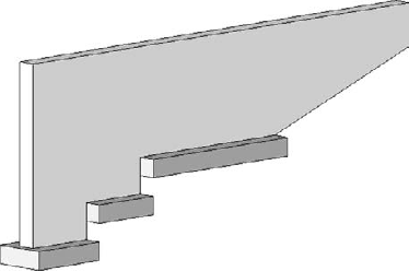
You must create a closed loop with no overlapping lines before the sketch will be considered valid. When you have finished completing the sketch to modify the extents or location of the base of the wall, you will need to select Finish Wall from the Wall panel on the contextual tab. Your wall and footing should now step similarly to what is shown in Figure 8.32. This example already has the wall foundations modeled, but if they were not already in the model before editing the profile, it would not be a problem. When you select the wall to place the footing, the wall footing will host to the base of each segment of the stepped profile of the wall.
Sloped Wall Profile = No Wall Foundation
Wall foundations do not attach to a wall whose base is sloped. The sloping of a base of a wall can be achieved by attaching the base to a sloped reference plane or structural slab or by editing the wall's profile. Either way you will be unable to place a wall foundation to attach to the base of the wall. In the case where you have edited the wall's profile, the wall foundation will attach only to the portions of the wall that are horizontal.
You may have noticed that these stepped footings are not shown exactly how they are going to be built. Typically the bottom of the step will be sloped, and part of the footing will be thickened where the footing overlaps the step area, as shown in Figure 8.33. You will need to decide if it makes sense to take it to the next step and model this portion of the step footing or not. It depends on the level of detail that you require in your model and how much effort you want to put into keeping the footing accurately shown in the model.
This portion of the stepped footings is created with the Isolated Foundation tool, similar to a spread or column footing. Since Revit Structure does not include a stepped footing family in its library, you will need to create or acquire one yourself. Chapter 18 includes information for creating one to help you on your way. Of course, you could do this with an in-place family by using the Form tools for creating extrusions and blends, but that eventually becomes a nightmare to manage and is not recommended. The foundation component family allows you to build much more flexibility into your project so when changes occur, your efforts of managing the model are reduced.
There is actually more to learning how to work with the properties of a wall foundation and how they function once they are in your project than there is to learning to place them. Wall foundations can be some of the easiest things to put into your project. As long as you are locating the base of your walls at the top of footing location and you have configured your family types to behave as you would expect, your wall foundations will fall into place.
Now that you hopefully fully understand how a wall foundation behaves, the properties it has, and how you work with it before and after it is placed, let's discuss how to add them into your project. It might seem odd that we talk about this last, but as we said earlier, you should really acquire a good understanding of the settings for the various elements Revit Structure deals with as well as how you can manipulate them before you randomly start modeling them. Without this understanding you risk modeling things improperly or not in the best way for modifying and working with them as your project progresses.
Wall foundation cans be placed in any view in which you are able to select a wall. You might find that it is easiest to place them in a 3D view where you crop the view with a section box to show only your foundations. Orient the view so that you can select those walls that require wall foundations, and you can see them appear as they are placed. To start, you choose the Home tab
Once the tool has been selected, the Ribbon will switch to the Place Wall Foundation contextual tab, as shown in Figure 8.35.
If you recall what the options were for placing an isolated foundation, you will see by looking at this contextual tab that a wall foundation does not have as many. The Ribbon has the Element Properties button, a Type Selector, and on the Options bar the option to place Multiple. If Multiple is checked, you will need to choose Finish Selection from the Ribbon to accept your wall foundation placements. The options are limited because a wall foundation attaches to a wall only, so your only options are to select a wall to place it by. The placement of your wall determines the initial location of the wall foundation; without a wall you are unable to place it.
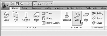
Figure 8.34. Choose the Wall tool from the Foundation panel to start the placement of a wall foundation.
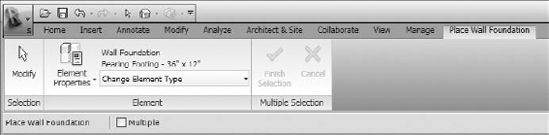
Figure 8.35. The Place Wall Foundation contextual tab has limited options for placing wall foundations.
You are ready to start placing wall foundations. Start selecting walls. As you do, you should see the wall foundation appear at the base of the wall you are selecting. If you are in a view whose view settings are such that it cannot display the wall foundation, you will see a warning like the one shown in Figure 8.36. This warning is just telling you that your footing was placed, but your view settings are such that the footing cannot be displayed. Several things could make it not visible in the current view.
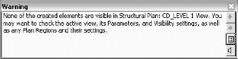
Figure 8.36. Warning stating that none of the recently created elements are visible in the current view
Here is a quick list of things you can check:
The View Range settings in the View properties
Whether the object's category or subcategory is turned on
The Design Option settings
The Phasing settings and filters
Whether any filters are applied to the view
The Plan Regions in the view
Once a wall footing has been placed under a wall, you will be unable to select it again. This is Revit Structure doing what it is supposed to do, which is not allowing you to place multiple wall foundations under a wall. You wouldn't pour two wall foundations out in the field on top of each other, so why would you want to model it that way?
After you finish placing your footings, you will need to select Modify from the Place Wall Foundation contextual tab or use the Esc key from your keyboard to stop the tool. Until you do this or you select another tool outside of the contextual tab, the Place Wall Foundation mode keeps running.
Checking the Multiple option from the Options bar will make the Finish Selection and Cancel tools available (Figure 8.37).
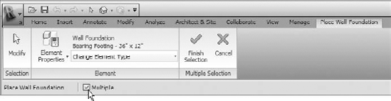
Figure 8.37. The Finish Selection and Cancel tools are available when the Multiple option is checked.
The basic steps for using the Multiple option for placing wall foundations are as follows:
After you choose the Wall tool from the Foundation panel, check the Multiple box on the Options bar. Note that the Finish Selection and Cancel tools in the contextual tab become activated.
Select the type of wall foundation you want to place from the Type Selector.
Select groups of walls that require a footing by using one of the following methods.
With a right-to-left crossing window, those wall elements that are selected by the window will be part of the selection. With a left-to-right crossing window, those wall elements that are completely within the crossing window will be selected.
Select walls individually by selecting a wall and holding down the Ctrl key to add to your selection or holding down the Shift key to subtract from your selection.
While hovering the mouse cursor over the wall, press the Tab key from the keyboard to select a chain of walls. All walls that are chained (endpoint to endpoint) together will be highlighted. At this time you can select the wall, and all of the chain walls will be selected. This method can be used in conjunction with using the Ctrl or Shift key method from above or without the Multiple option checked.
When selecting walls in the Multiple selection mode, wall foundations will not display as the walls are selected. They will appear after you choose Finish Selection from the Place Wall Foundation contextual tab
With the use of the Isolated Foundation and Wall Foundation tools, you will be able to model just about all of the various foundation types that will be in your project. The content to do so might not be set up for you, but hopefully after reading the section on isolated foundations you have a better understanding of how to create that additional content as well as configure its settings. Since a wall foundation is a system family, you deal with only one shape and basically one placement method: pick a wall. Much of working with these tools is similar to how other tools work with other elements of different categories. The Foundation tool is no different. You work with this tool the same way you work with the Structural Floor tool. The main differences are that it does not have all of the sloping capabilities of a structural floor and elements it creates are not assigned to the Floor category.
Exercise: Placing Wall Foundations into a Project
For this exercise you can use the Wall Foundations.rvt and Wall Foundation_Complete.rvt files (from the book's companion web page at www.sybex.com/go/masteringrevitstructure2010). You will go through the steps of adding a stepped footing with the Edit Profile method as well as the steps for placing wall foundations into your project.
Stepping the Wall with Edit Profile
Open the
Wall Foundations.rvtfile.Open the Section - Edit Wall Profile Section view.
Select the foundation wall that is running between grids 1 and 2, and choose Edit Profile from the Modify Walls
The Ribbon will switch to the Modify Walls
Choose Finish Wall from the contextual tab.
Switch to a 3D view and admire your new stepped wall.
Open the 3D_Level - Slice view.
Choose the Home tab
Verify that the Type Selector is set to use Bearing Footing - 36″ × 12″.
Move to the drawing area and start selecting foundation walls. There is no need to worry about using the Ctrl and Shift keys to create a selection because you are in a single-pick placement method and each pick of the wall will place the footing and attach it to the bottom of the wall.
Notice that wall footings are placed at each step for those walls that have their profile edited to form steps. The other wall steps that were already created were done by using the Split tool. Each step is an individual wall, which means you have to select each one to attach a wall foundation to it.
Placing Wall Foundations Using Multiple
Open the Level 1 - Structural Plan view.
Choose the Home tab
Verify that the Type Selector is set to use Bearing Footing - 36″ × 12″.
This time check the Multiple check box on the Options bar. Notice the Finish Selection and Cancel tools become available to use.
Create a window selection by making a right-to-left crossing window to select all of the foundation walls that are on the east wing. As you select walls, you will not see the wall foundations appear. Only the walls will be highlighted.
There is no need to worry about filtering elements out of your selection that are not walls because while you're in the Place Wall Foundation mode you can select only walls. You do have to worry about which walls you are selecting. In this exercise we have only foundation walls in the model. They are also modeled as one wall. If you had a foundation wall that was modeled with two walls on top of each other that are not a stacked wall type to form a brick ledge, you would end up with a wall foundation being placed in an unexpected location.
When your selections are complete, choose Finish Selection from the Place Wall Foundation contextual tab. Your wall foundations should appear.
Choose Modify from the same tab or press Esc on the keyboard to close the Place Wall Foundation contextual tab.
Continue using the methods above to finish placing the wall foundations. Compare your work with the sample file Foundations_Complete.rvt. With the quick pick/select method of placing wall foundations, you can quickly place wall foundations into your project.
There is really no need to get too in depth with the Foundation Slab tool in this chapter. It really works the same way as the Structural Floor tool, which is discussed in Chapter 5 along with using the Foundation Slab tool for a slab on grade. Like the wall foundation, the foundation slab is a system family. All of its functionality is built into the software itself, and you do not create separate families when creating foundation slabs. You only create new types within the project. One of the biggest differences between the two tools (Structural Floor and Foundation Slab) is that the elements the Foundation Slab tool creates are assigned to the Structural Foundation category, just like the isolated and wall foundations. The other difference is that it does not have the functionality with regard to sloping that the Structural Floor tool has.
We don't know about you, but because an awful lot of slabs on grades have multiple slopes to them, we believe they would be best modeled by using the Structural Floor tool, which has subelements that allow you to manipulate its points and edges. The Foundation Slab tool allows only a sloping arrow that permits you to define the desired slope of an entire slab or a portion of a slab. Only one slope arrow is permitted per slab element or slab sketch.
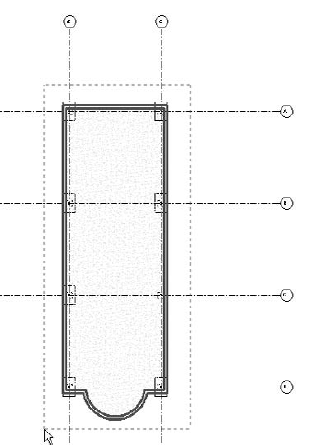
There are cases such as those slab on grades that don't slope where you will be able to use the Foundation Slab tool, but you will find that its biggest use will be for foundations and footing-related elements—foundations such as those that cannot be modeled successfully by using the Isolated or Wall Foundation tool. Elevator pit slabs, tower crane pads, strapped footings, irregularly shaped footings, and foundations that are required to be directly adjacent to existing construction are where the foundation slabs can be best used. Elevator pads and tower crane pads are rectangular in size like the isolated foundation component family, but controlling their size and placement in the model is easier with the sketch lines that are used in the foundation slab. It's much simpler because their size is usually determined by other elements such as walls and other foundation elements, and editing their size can be done more easily by revising the sketch in place among the related elements.
Since foundation slabs are assigned to the Structural Foundation category, they take on the same display characteristics as other foundations do in your views. In cases where the foundation slabs are being used as other footings and are square or rectangular in shape, you can use the foundation slab's Width, Length, and Default Thickness properties in a Structural Foundation Schedule. Chapter 11 will discuss more on creating schedules and quantities in Revit Structure. However, if the shape of the foundation slab is not rectangular with one length and one width, the parameter will not contain any values.
To access the Foundation Slab tool choose the Home tab
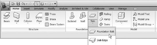
Figure 8.38. The Foundation Slab tool can be accessed in the same panel as the Isolated and Wall Foundation tools.
You will also see that a Slab Edge tool exists in the same location. This same tool is used to create slab edges for a structural floor. It uses the same component families and assigns the slab edge to the Floor category. Keep this in mind if you are placing a slab edge onto the edge of a foundation slab. Even though it is a slab edge from the Foundation Slab drop-down, the slab edge is assigned to the Floors category, while the foundation slab is in the Structural Foundation category. The Slab Edge tool is located with the Foundation tools rather than with the Floor tools for your convenience. If you are looking to put a slab edge onto a foundation slab, you are more than likely going to go the Foundation tools to look for it.
After you select the Foundation Slab tool, the Ribbon will switch to the Create Floor Boundary contextual tab, as shown in Figure 8.39.
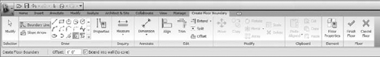
Figure 8.39. The Create Floor Boundary contextual tab for a foundation slab is the same as it is for a structural slab.
Within the contextual tab tools are available to sketch the boundary of the foundation slab. Chapter 5 discusses how to use these additional tools to create a sketch for a slab-on-grade situation. Whether you are creating a sketch for a slab on grade or a footing-related element, the process of creating and working with the sketch and the finished element is the same.
Revit Structure's default template already has several foundation slab types created for you. They are:
6″ Foundation Slab
8″ Foundation Slab
10″ Foundation Slab
12″ Foundation Slab
You can create new types from these by going to the Type Properties dialog box and clicking the Duplicate button. Give the slab a new name and change its properties accordingly. You can view the properties of any of the foundation slab types in the Project Browser. Find the Families
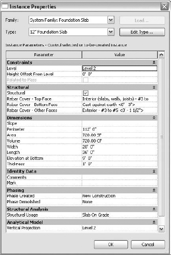
Figure 8.40. The Instance Properties dialog box of a foundation slab has read-only parameters in the Dimensions group.
Within the Instance properties of a foundation slab you will find read only parameters under the Dimensions group such as:
Slope (cannot be shown in a schedule)
Perimeter
Area
Volume
Width
Length
Elevation at Bottom
Thickness (cannot be shown in a schedule)
Default Thickness (located in the Type Parameter)
You will see that the instance properties is where the Thickness of the foundation slab is located, but it is the Default Thickness parameter located in the type properties that is shown in a schedule. Take advantage of these parameters, as most of them can be used in a Schedule/Quantities schedule to collectively view information about the foundation slabs in your project. You will also see a Structure parameter in the Type Properties of a Foundation Slab as shown in Figure 8.41.
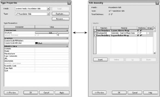
Figure 8.41. Access the Edit Assembly dialog box to see the layers of a foundation slab through its Type properties.
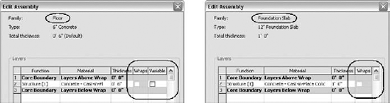
Adjacent to this parameter is an Edit button where you can edit the assembly (layers) of the foundation slab. As we said before about other characteristics of the foundation slab, it is not much different than a structural floor. Figure 8.42 shows that a foundation slab does not have a Variable setting that allows you to vary the thickness of a specified layer. This is because a foundation slab does not use subelements to slope its surface and edges.
Foundation slabs, regardless of what they are used for or how they are created, are placed no differently than structural floors. You will need to decide what tool is best in your environment for your specific situation. Each project will bring unique foundations that may not be best modeled the way you modeled them on a previous project. Knowing how these tools work will give you the knowledge to make those decisions.
- Create and work with isolated foundations
Knowing the various methods available for placing isolated foundations into your project allows you to quickly and accurately place them into your project.
- Master It
What are some of the methods you can use to place isolated foundations into your project?
- Create and work with wall foundations
Unlike an isolated foundation, a wall foundation is a system family, which has most of its behavior predefined in Revit Structure. When working with the wall foundation, the value of the Structural Usage parameter determines how it behaves in your project.
- Master It
What values can be assigned to the Structural Usage parameter, and what are their biggest differences?
- Create and work with foundation slabs
Foundation slabs are created with the same methods you use to create a structural floor. Knowing how to work with structural floors means you already know how to work with foundation slabs.
- Master It
What are the two biggest differences between a foundation slab and a structural floor?