
The power of Revit Structure is no more evident in any capacity than in the procedures involved in the placement of reinforcement. To say this topic ties it all together is an understatement. In normal AutoCAD, AutoCAD Architecture, and MicroStation, reinforcement is simply a separate entity. You draft it yourself. It stands to reason that an application that allows you to place, for example, a #4 bar with a given spacing as opposed to a "donut" is a much better way to think when it comes to "drafting."
In Revit Structure, reinforcement is supplemental to the item that hosts it. With that being said, Revit Structure gives you the ability to control reinforcement long before you even place a bar (rebar) in a wall, a footing, a column, or a pier. You are provided with settings that allow you to control reinforcement cover in both the object's Element properties as well as global Revit Structure settings. Revit Structure allows you to place predefined bars via a powerful new tool called the Rebar Shape Browser, and it gives you the ability to create your own rebar and add it to the library without leaving the model to create a new family.
In this chapter you will learn to:
Configure rebar settings
Model a 3D rebar
Add rebar shapes
Placing a 3D rebar in Revit Structure is pretty easy. The best thing about it is that you can still basically draft reinforcement, as we explained earlier in this chapter, but now the reinforcement will allow you to specify centering and will also let you to choose from a menu of predefined shapes.
Of course, where there is 3D there are settings that we will need to look at before actually placing the bars are in the model. We need to know how thick our rebar is going to plot, and we also need to see where the rebar will appear visually unobstructed. Some of these settings are located in different areas. The following sections describe where to access these settings; we'll begin with the Object Styles dialog box.
Real World Scenario: What about 2D Rebar?
There are many items in Revit Structure that should be fully modeled in 3D. There are also just as many items that, simply put, could not. Concrete reinforcement is probably the one item that falls into that gray area of "Should I model all of this in 3D, or do I draw it in?" It can be a tough decision to make in terms of what you are looking to get out of the project. On one hand, if you do model the entire project with the proper reinforcement, you can rely on the quantity takeoffs and the reinforcement scheduling to be accurate. On the other hand, if you model all of the reinforcement, it will take longer, and the model will quickly grow in size. We recommend that you look at the overall project. If it is a 650-foot-long military barracks or a football stadium, then you might want to consider placing 3D reinforcement only for the items you will be specifically cutting sections of. If it is a more manageable project in terms of size, then the advantage of fully reinforcing the model can outweigh the disadvantage of the initial time spent and the subsequent increase in the file size.
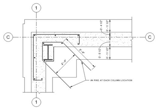
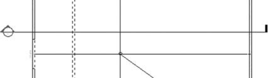
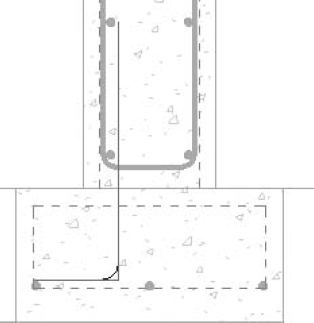
Sometimes, this decision is not easily made. There will be times where you do need to illustrate reinforcement but cannot afford either the time or the file size. Here you would simply draft the reinforcement. The following illustration displays a typical detail condition showing rebar both in plan and section; drafting rebar is as simple as using an appropriate detail line and whatever bar bends you need.
But this chapter is about real model reinforcement, not detail lines. Line styles and how they can pertain to your company standards are covered in depth in Chapter 17. If you are going to be simply drafting reinforcement as you did in AutoCAD, it makes sense to have a template set up that allows you to choose the line styles you want.
Adding 2D Rebar Detail Components
In AutoCAD it's called a donut. Some firms will make a block out of that donut, so if it changes, all of the bars will be updated. What are we talking about? We are referring to the perpendicular bars that need to be placed into the model. You do this by using the Detail Component tool on the Annotate tab. Once you click this button, you can then go to the Type Selector and pick the Rebar Detail family. You can then place the "sectioned" (horizontal in the case of a plan view) bars in the view, as shown in the illustration above. If you do not have the rebar family loaded in your model, click the Load Family tool. Browse to Detail Components
So, as you can see, there is a tremendous benefit to using a basic 2D drafting method of adding reinforcement with positive downstream effects. But you are here for something real, not faked, so keep reading!
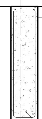
The first item we'll examine is how the bars will appear in terms of their plotted line weight. The out-of-the-box appearance has foundation walls graphically thicker than the reinforcement, as shown in Figure 10.1. This just can't be! Although you may have the settings correct at your firm, let's get a handle on where these settings are and how you adjust them.
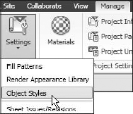
As shown in Figure 10.2, select the Manage tab
In the Object Styles dialog box are three settings you need to configure:
These items are set to 1 by default for both Projection and Cut. Since a line weight of 1 is ridiculously thin, we recommend that you set them to at least 4, depending on your firm's standards. See Figures 10.3 and 10.4. Refer to Chapter 17 for concepts in developing overall line weight methodologies. Gaining control of object styles in Revit Structure will greatly enhance your satisfaction with the end product.

It is also worth mentioning that if you do have to change a setting in a specific project, you'll have to make the same change for the next project. So be sure to add these settings to your template file, or contact the person in charge of your company's Revit Structure standards. You know how you want the reinforcement to look as far as line weights are concerned.
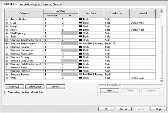
Figure 10.4. The Model Objects tab in the Object Styles dialog box lets you controls the line weight for each object type.
Now it is time to configure some settings that will determine the coverage that will be applied to the bars in relation to walls, slabs, and footings.
As mentioned in Chapter 6, each wall type has its own cover settings. You can define the minimum setback from the face, top, or bottom of a wall or foundation for which Revit Structure will allow you to automatically place reinforcement. As the rebar is graphically being placed into a wall, beam, foundation, or slab, you will see blue alignment lines. These lines, as shown in Figure 10.5, indicate the minimum allowance of cover. Once you define the reinforcement, as shown in Figure 10.6, the cover settings will serve as the guidelines for the pattern.

Figure 10.5. Notice the faint hidden lines, indicating the cover distance.
Cover settings are Instance parameters that are associated with each wall, beam, foundation, and slab. If you select any of these items, such as a concrete wall, and click the Element Properties button on the Options bar, you will see a Structural group. This group contains the cover settings for that specific item, as shown in Figure 10.6. The settings are contained in a drop-down list to the right of the parameter. There are eight choices by default. The increments of the offsets are built into these settings.
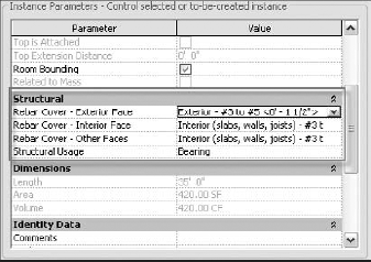
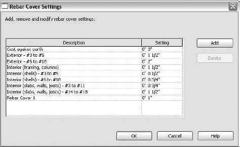
These eight choices are predefined settings built into the Revit Structure default template. You can add or subtract from these items as you see fit, as shown in Figure 10.7. To access these options, activate the Home tab
Simply click the Add button, and you are off to adding a new setting. This is one instance where the out-of-the box Revit Structure settings are sufficient—mostly. We recommend that as you are creating these new settings you keep in mind the fact that you should not overdo it. Yes, some projects will require more cover situations than others, but give careful consideration to which settings should go into the templates and which settings should be specific to a project. Once these settings are set, you are ready for the next step: adding the bars to the model.
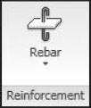
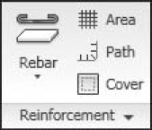
As sections are cut, and the detail views start to populate the Project Browser, you may notice that when you select a beam or footing a Reinforcement panel appears on the Ribbon, as shown in Figure 10.8.
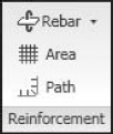
However, when you select a slab or wall element, you get a slightly different set of tools. This is because these object types are system families (built-in families), and Revit Structure perhaps has a better level of intelligent control of them. As shown in Figure 10.9, you get extra tools for the face and path of rebar you place.
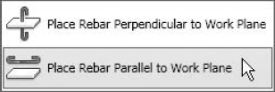
Each of these tools allows you to place reinforcement in an object, depending on the current view. For example, if you are looking at a section of a wall and you select it, the Modify Wall Framing ribbon appears. On that ribbon is the Reinforcement panel, and within that is the Rebar tool. Since you are placing stirrup cages, expand the Rebar tool and choose Place Rebar Parallel to Work Plane, as shown in Figure 10.10.
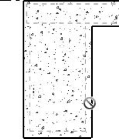
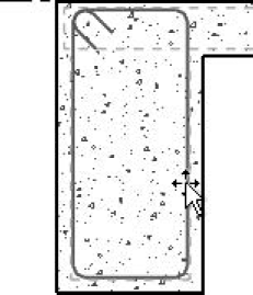
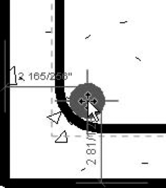
As you rest your cursor over the beam, you will see dashed blue alignment lines, as shown in Figure 10.11. This is how Revit Structure indicates the farthest location you can get to the face of an item before the rebar cover settings disallow the placement. If you exceed this distance, Revit Structure will disallow the placement. If you move up and click-right on the blue alignment line, Revit Structure will place the rebar into the model, as shown in Figure 10.12. The sides and bottom of the rebar will be set at the specified framing cover settings. The top is controlled (in this example) by the slab cover settings.
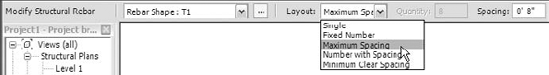
With the rebar in place, you can now select it and view the Options bar. As shown in Figure 10.13, you get placement controls you use to specify a layout. A single stirrup can be set to run the length of the beam at the spacing specified here.
After the spacing has been set, you may notice that Revit Structure will keep a running count (Quantity), as shown in Figure 10.13. Get used to having this kind of information right in view!
Adding reinforcement in Revit Structure is great. Once the rebar is placed in the model, you can then configure its visibility state by view.
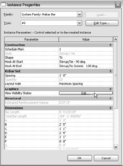
One issue with reinforcement in Revit Structure has always been that reinforcements will show up in views where you don't want them to. Each piece of reinforcement has its own Instance parameter, which will control the appearance of reinforcement as it relates to other views. To gain access to the settings for the visibility states of a specific reinforcement item, you must select the rebar and review its properties. When the Modify Structural Rebar tab appears, click the Element Properties button. In the Instance Properties dialog box, you will see a Graphics category. In the Graphics category, you will see a View Visibility States parameter, as shown in Figure 10.14. Once you click the Edit button, you will be able to control exactly where this specific reinforcement will appear.
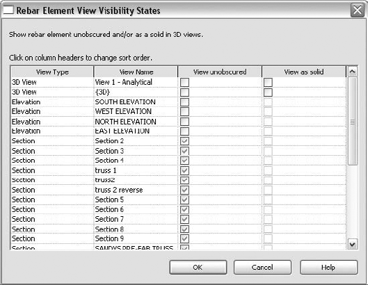
In the Rebar Element View Visibility States dialog box, you will see that most of the views are unchecked, as shown in Figure 10.15. The checks do not actually turn the bars off—they merely allow the bars to be obstructed by the body of the host element. When viewed unobstructed, these bars will show through the host walls, foundations, and slabs. By default, the default views that show reinforcement unobstructed are sections. Typically, plans and elevations have rebar obstructed by the host.
Similarly to adding bars parallel to the current work plane, you can add horizontal bars that run perpendicular to the current work plane in the same view.
Using the same procedure as for adding parallel bars, you can place bars that are perpendicular to the work plane. In a sectional view, as illustrated earlier in Figure 10.12, these bars would be considered horizontal bars. To add these bars, simply select the beam again. You can then click the Place Rebar Perpendicular to Work Plane button. By default, these bars will come in based on a horizontal spacing. As you are placing the bar, press the spacebar to flip the orientation to a vertical plane. As you place the bar, the same cover planes will appear, limiting the bar's placement, as shown in Figure 10.16. If you were to place the bar at the top of a slab, it would not exceed the cover set for the slab top.
Once the bar is placed, you can then select it and alter the layout and the spacing. If you change the Layout to Fixed Number and change the Quantity to 3, the bars will array along that face of the beam, as shown in Figure 10.17. You can then simply mirror the bars to the opposite face of the beam once they are in place.
The same procedure can be applied to walls, footings, and slabs as well. Once you have conquered applying reinforcement to one object type, you have mastered them all!
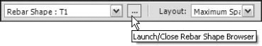
One of the powerful features in Revit Structure is the Rebar Shape Browser. As you select an item to place reinforcement in, you then select whether you want the reinforcement perpendicular or parallel to the current work plane, as discussed earlier. Once you determine the direction of the bars, you will see a list on the Options bar. It allows you to select a rebar shape and shows the type, as shown in Figure 10.18. To the right of the list is a builder button (...). This button will turn the Rebar Shape Browser on or off.
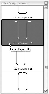
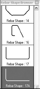
With the Rebar Shape Browser turned on, as shown in Figure 10.19, you will see that many default choices are built into the program.
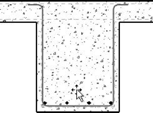
As you find a shape and drag it into the model, you will see that the rebar cover settings are, again, dictating the height and width of the bar configuration, as shown in Figure 10.20.
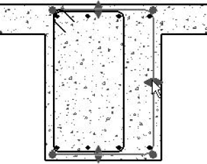
Once the bars are placed, you can select them. Notice there are quite a few grips and shape arrows. These provide you with the ability to freely change the bars to a new location if the default position is not acceptable, as shown in Figure 10.21.
Once the bar is in place, you can change the spacing and the view settings. If you want the bars to display in 3D as a 3D solid, open the Instance Properties dialog box and change the View Visibility States settings to View Unobscured in {3D}. You can also check View as Solid. Refer again to Figure 10.15.
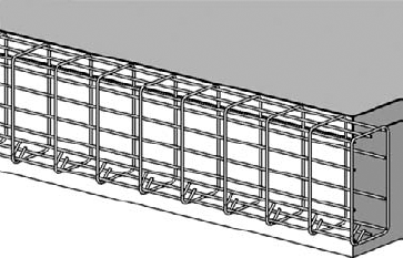
You place bars that are perpendicular to the current work plane in the same manner. Select the item you want reinforced, and click the Place Rebar Perpendicular to Work Plane button on the Reinforcement panel. In the Shape Browser, make sure you have the bar you want, and simply place the bars in the model just as you would if you were placing blocks. Remember to set the visibility state to show unobstructed in the 3D view if so desired; as shown in Figure 10.22, it can be very informative.
Revit Structure, as you can see, allows a tremendous amount of flexibility in terms of allowing you to model rebar as efficiently as possible, while still maintaining a true 3D modeling environment. This procedure works quite well until you come to a situation where the bars provided by Revit Structure do not provide enough choices to model a specific situation you may have. It is here that Revit Structure allows you to sketch your own rebar shape and add it to the project.
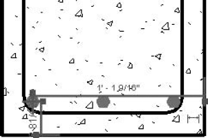
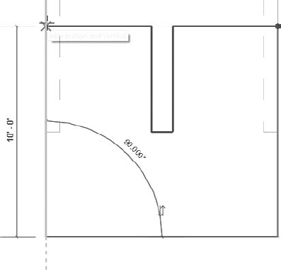
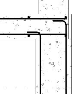
The first time you start using the new Rebar Shape Browser, you will discover that there is no way Revit Structure could possibly include every shape possible—especially in situations where one component needs to be doweled into another. To sketch rebar in a wall, beam, slab, or foundation, simply select the component that is to receive the reinforcement. On the Reinforcement panel, select Place Rebar Parallel to Work Plane. Then on the Place Rebar tab, click the Sketch Rebar button. Revit Structure will prompt you to select the item you want to place the reinforcement in again. Once you select the object, you can then freely sketch the reinforcement. For example, you might use this method for doweling a foundation wall into a footing, as shown in Figure 10.23. You may notice that as you are drafting, if you have a 90-degree corner, Revit Structure will add the to-scale bend radius for you. Revit Structure knows you are drawing a rebar, so it stands to reason that things like this will be automatic.
One nice feature included with the rebar modeling tool is that it will automatically add the new rebar sketch to the Rebar Shape Browser for future use in this model, as shown in Figure 10.24.
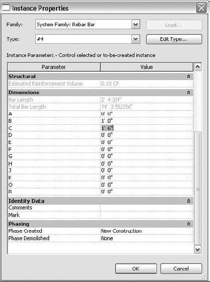
The new rebar that was created has the same intelligence as the default rebar shapes. If you select the rebar you create, you will see in the Options bar that you can still specify a unique spacing layout for each instance of the reinforcement. Also, if you select the new reinforcement and click the Element Properties button, you will see that you can change the rebar size as well as the dimensions (A through R), as Figure 10.25 shows.
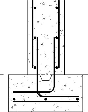
Figure 10.23. Using the rebar sketch method is simple enough even for standard conditions. For complex conditions, it is a must.
Although it seems we have explored all the methods there are for placing reinforcement into a model, there are more to go. Suppose you wanted to reinforce an entire slab in one shot. Or perhaps there are perimeter conditions you need to add to the model. Revit Structure will allow you to do these tasks with commands specific to each situation.
With the Area Reinforcement tool, Revit Structure will allow you to place rebar in an entire slab or wall in one action, thus eliminating the need for toiling over exact placement and configuration. However, it should be noted that area reinforcement is not visible in a 3D view.
To place area reinforcement in a slab, you will need to be in the plan view where the slab is shown. Once there, you select the slab that is to be reinforced. Once you do, the Reinforcement tools appear on the Reinforcement panel. Click the Area Reinforcement button shown in Figure 10.26.
This tool will put you into a Sketch mode. On the Ribbon, you can use Pick Lines tool and start selecting the edges of the slab. The first line you click will have two shorter lines on either side, similar to the sketch lines when using the Beam System tool. This indicates the slab direction. If this is incorrect, you can change the direction by clicking the Major Direction tool on the Draw panel, shown in Figure 10.27, and then pick a new starting edge line.
Another essential tool is the Area Properties button located on the Element panel of the Create Reinforcement Boundary tab. This opens a dialog box that will gain you access to the configuration and type of reinforcement that is going into your slab. A nice thing about the properties in area reinforcement is that you can specify that the reinforcement have two different layers (with separate properties for the type and spacing of the major and minor bars in each layer), as shown in Figure 10.28. Each of these layers can be turned off if one or the other is not needed (see Figure 10.29).
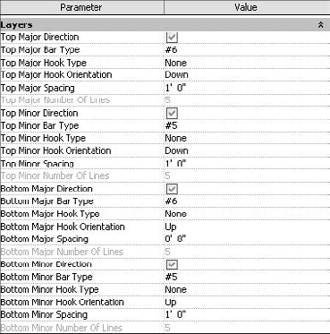
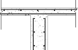
Figure 10.29. Area reinforcement in the slab section shows both top and bottom bars (remember this was added in a plan view).
In the Instance Properties dialog box, you are also given the choice to change the additional top and bottom offsets. These will be added to the cover settings, and Revit Structure will place the reinforcement at the specified offset. For example, if the cover setting for the slab is 1
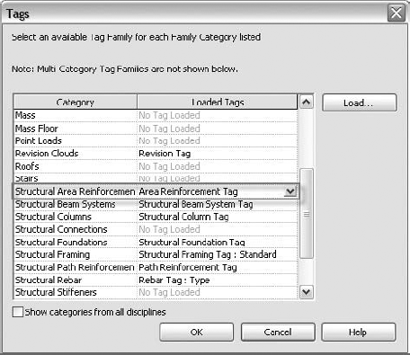
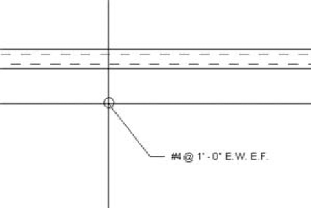
In plan, the area reinforcement will automatically be tagged. This behavior can be changed, and a different custom tag can be specified. Select the Annotate tab on the Ribbon
The tag will appear automatically, as shown in Figure 10.31. If you do not want to tag the item, you can delete the tag—it will not affect the actual reinforcement.
Area reinforcement is perfect for reinforcement of structural slabs, but it can be applied to walls as well. The procedure is nearly the same.
Placing area reinforcement in a wall is sometimes preferred over having to place bars individually and then having to specify the spacing. Each method can have its advantages, and after you know how to do both, you can determine which process best suits your situation.
To place area reinforcement in a wall, you must first display an elevation that is looking straight at the wall that is to be reinforced.
There Is a Different Way
This chapter has enforced the procedure of selecting the item that will receive the reinforcement and then clicking the proper tool. You can, however, utilize the Home tab
In the elevation, you can select the wall and click Area Reinforcement found on the Modify Walls tab. This will display the Create Reinforcement Boundary tab, where you can create sketch lines. At this point, you can sketch the perimeter of the reinforcement, similar to placing the reinforcement in a floor (see Figure 10.32). Make sure you do not exceed the actual boundary of the wall when doing this.
Figure 10.32. The area reinforcement sketch profile. The double lines on the left sketch line indicate the major direction of the bars.
Once the sketch is finished, click Finish Area. Now if you cut a section through this wall, you will see that the reinforcement is laid out as expected, as shown in Figure 10.33. If the bar layering is reversed from what was expected, you will need to use a view in which you can see the reinforcement (such as a section). Select the area reinforcement, and click Edit Boundary from the Modify Structural Area Reinforcement tab. You will then be sent back to any elevation view. In the resulting view, you can change the Major Direction setting as needed.
Now that the mass areas are reinforced, we can move on to reinforcement of specific areas, such as providing additional dowels to the perimeter for the slab by adding what Revit Structure refers to as path reinforcement.
There are occasions where you are going to need to reinforce the edges of a slab independent of area reinforcement. This is where the Path Reinforcement tool comes in handy. Like the other Revit Structure Reinforcement tools, you apply path reinforcement to a slab by first selecting a floor that needs the reinforcement and then clicking the Path tool (as shown in Figure 10.34), or you can click the Path tool directly from the Home tab, followed by making a floor selection.
While in Sketch mode, it is a good idea to click the Path Properties tool and then use the Instance Properties dialog box for the path reinforcement to configure the bars, as shown in Figure 10.35. Within the dialog box, you can specify in which direction the bars will hook. By default, the bars are hooking Up. If the wall was in a slab-supporting situation, you would need to change the hook direction to Down so that the bars could hook into the top of the bearing wall. Also, you can turn on alternating bars. This allows you to stagger the bars at whatever increment you have specified. The hooks are specified at each end of the bar.
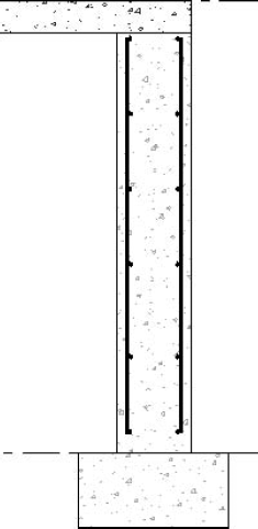
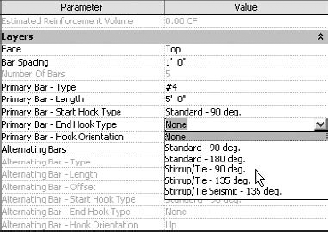
Figure 10.35. Parameters for edge reinforcement allow you to further control the function of the bars, such as primary spacing and the addition of alternating bars.
Once you have finished adjusting the properties, click OK to return to the view. From there, you can use the Draw panel to create lines along the perimeter of the reinforcement, as shown in Figure 10.36.
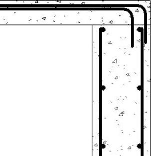
Once you've sketched the path, you can click Finish Path, and Revit Structure places the reinforcement into the slab. It is a good idea to cut a section through the path reinforcement and look at the spacing and the bar configuration, as shown in Figure 10.37. If it is not as expected, you can select the bars in that view, and click the Element Properties button in the Modify Structural Path Reinforcement panel. You can then configure the properties without having to go back into Draw mode. Figure 10.37 shows the reinforcement with a 2″ offset for the alternating bars.
The plan view will show the depth of the bars as well as the tags and symbols. You may not want to show all of this. For example, you can select the path reinforcement outline and use the right-click context menu to select Hide in View
Another item to mention in all reinforcement is the end hook configurations, as shown in Figure 10.39. You can override the end hooks of any reinforcement by simply selecting the bars and clicking the end hook icon that appears. Many times this is an easier method than trying to specify an end hook condition in the Instance Properties dialog box. You may find it necessary to be able to graphically see in which direction the bars are going. It is also sometimes hard to determine which end of the bar you are trying to configure. This on-screen toggle makes the task much easier.
Compared to simple drafting performed in AutoCAD, adding reinforcement to a Revit Structure model is not harder but is certainly different. With the many options available to aid in the placement, this process is obviously beneficial. Also, there is a downstream benefit. As you will see in Chapter 11, reinforcement can easily be scheduled and quantified after it has been placed in the model. This is a tremendous benefit. Keep in mind, however, that if you are to provide scheduling and quantities, you must be diligent in rebar placement. You can expect Revit Structure to report back only what you put into the model.
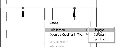
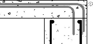
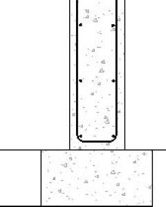
Figure 10.39. End hook configuration shown with the dowels extending into the top of the foundation wall
Exercise: Using Revit Reinforcement
In this exercise, you can either use the Revit Structure model provided at the book's companion web page at www.sybex.com/go/masteringrevitstructure2010, or you can follow along with your own model. The object of this exercise is to get you comfortable using the Revit Structure reinforcement and to make you never want to go back to drafting again. To start, follow these instructions:
Open the file called
reinforcement model.rvtfrom the book's companion website. You may substitute your own model if you wish.The first procedure is to configure the settings so the reinforcement looks correct. To do this, activate the Manage tab

Starting from the top of the list, change the following line weights (the first value is Projection, and the second is Cut):
Click OK to close.
The next order of business is to place area reinforcement in the slab. To do this, use the 1ST FLOOR level view and select the slab. You may have to select an area around the corner of the model and click the Filter button on the Ribbon. Once you're in the Filter dialog box, select only Floors and click OK.
On the Reinforcement panel of the Modify Floors tab of the Ribbon, click the Area button.

From the Draw panel, click the Rebar Line button. (It should be on by default.)
Then click the Pick Lines tool from the Draw/Pick gallery.
Select all the outside edges of the slab. Remember that you must have a completely closed loop with no gaps or overlapping lines. If needed, use selection filters to select the floor object.
Click the Area Properties button.
Verify the Layout Rule is set to Maximum Spacing.
Keep the rest of the defaults the same. Remember, you can always go back and change the properties after you review a section through the model.
Click OK. Then click Finish Area to complete the placement.
Revit Structure will place the rebar into the slab. Create a new section through the slab.
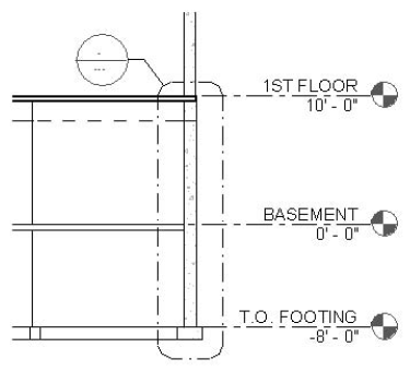
Create a callout of the right side of the section where the 12″ wall/beam meets the 10″ wall extending down to the footing. Make the callout's scale

Open the callout view. Select the 12″ concrete bearing wall.
Click the Place Rebar Parallel to Work Plane button on the Ribbon.
In the Rebar Shape Browser, select Rebar Shape: S5. Use the spacebar to set the hooks to the top and pointing to the left. Select the rebar and grip-stretch the ends into the slab.
Now that the rebar is "roughed in," you can alter its behavior by accessing the instance properties.
Select the new rebar, and click the Element Properties button.
For the Rebar Set category, set the Layout Rule to Maximum Spacing, and set the Spacing to 1′-0″.
Click Edit Type.
Click Duplicate.
Name the rebar #4 with 12" hooks.
Under Hook Lengths, click the Edit button.
Make Stirrup/Tie – 90 deg equal to 1′-0″.
Click OK three times to close all open dialog boxes.
Select the same foundation wall again.
Click the Place Rebar Perpendicular to Work Plane button.
Select Rebar Shape: 00.
Press the spacebar once to orient the bar vertically. This change will not be noticeable.
Place the bar at the top cover alignment line and to the right of the vertical bar. Click the Modify button to stop bar placement and select the new rebar itself.
Use the Options bar and set the Layout setting to Maximum Spacing and the Spacing to 1′-0″.
Mirror the bars to the left side using the centerline of the wall.
Pan down to the where the wall bears on the footing.
Select the S5 bar and grip-stretch it out of the footing.
Select the horizontal bars and do the same.
Select the footing, and click the Place Rebar Perpendicular to Work Plane button.
Select Rebar Shape: 00.
Place the rebar to the bottom left of the footing in the corner of the cover alignments. Cancel Placement and select the bar.
Change the Layout setting to Fixed Number.
Change the Quantity setting to 3.
Select the 12″ foundation wall.
Click the Place Rebar Parallel to Work Plane button.
On the Ribbon, click the Sketch Rebar button.
Select the wall again.
Draw in a hooked dowel extending from the second bar into the footing.
Click Finish Rebar. Notice that the dowel is now added to the Rebar Shape Browser.
You can now perform common drafting tasks to repeat the efforts without going through the Instance Properties dialog box.
Change the Spacing setting to Maximum Spacing.
Change the spacing to 1′-0″.
Mirror the dowel about the centerline of the wall.
Select all rebar you have put into the model.
Click Element Properties and then click the View Visibility States button.
Check View Unobscured for all 3D Views.
Check View as Solid.
Click OK to close. Click OK to close the Instance Properties dialog box.
Display the default 3D view.
Change the view Detail Level setting to Fine.
If needed, change the Model Graphics Style setting to Shading with Edges.
Click the Show Thin Lines button on the View tab.
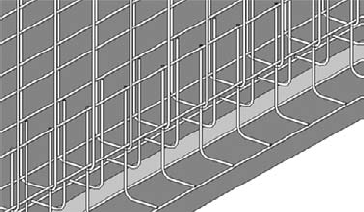
You can now see the massive amount of steel that goes into a wall like this. All reinforcements are generated using a section view. It is good to keep in mind that this section was generated by using tools that are no more difficult to use than those you'd use in actual drafting. As a matter of fact, most of these tools are much easier to use than those you'd use in standard drafting. You do not have to add a radius to bends, and you can clearly specify hook lengths as well. As you will see in the next chapter, this reinforcement can be put into a quantity takeoff and a reinforcement schedule. As you learn to draft, you will see that this reinforcement can be tagged automatically, allowing you to maintain consistency throughout the project.
- Configure rebar settings
In Revit Structure you can place reinforcement as actual objects as opposed to simple drafting. To do this correctly, however, you need to extensively configure the rebar settings for graphics as well as performance.
- Master It
Walls, footings, and slabs have cover settings that allow you to place reinforcement in a more organized and accurate approach. How is this done?
- Model a 3D rebar
Although Revit Structure uses a modeling approach, it is often necessary to be able to sketch reinforcement first and then add it to the 3D Shape Browser once it is completed.
- Master It
Placing 3D reinforcement can be done in two different ways. Describe both.
- Add rebar shapes
By default in Revit Structure, you have a multitude of reinforcements to choose from. These shapes are preloaded into the template file you are using. Revit Structure allows for the importing of additional shapes.
- Master It
You may be working in a model that was created in an older Revit Structure version. The model will not have any rebar shapes. How do you import the shapes?