06 Setup Menu

Kiwi the Parrot © 2016 Jim Keenan (Lomcevak)
The Setup Menu contains a series of settings for basic camera configuration that are not directly related to taking pictures. It covers things like Monitor brightness, battery information, firmware version, the default language, Wi-Fi, Bluetooth, smart device connectivity, and many other basic settings. Here is a look at the Setup Menu (figure 6.1).

Figure 6.1 – The Setup Menu
The settings in the Setup Menu are most likely the first ones you’ll configure when you prepare your new Nikon D500. You’ll have to set the Time zone and date, Language, and Copyright information—for embedding in the metadata of your pictures—among many other things.
Following is a list of the 36 functions available in the Setup Menu:
- Format memory card: This function allows you to delete all images from your camera’s memory card(s).
- Language: Choose the language you would like your camera to use from a list of 36 languages. Menus and screens will be displayed in the chosen language.
- Time zone and date: Set the Time zone, Date and time, smart device time synching (Sync with smart device), Date format, and Daylight saving time in your camera.
- Monitor brightness: Choose the brightness level for the Monitor on the back of your camera.
- Monitor color balance: Select the color balance of the Monitor. You can use a reference shot taken by the camera, such as a picture of a color chart, to calibrate the Monitor’s color balance.
- Virtual horizon: This function displays a virtual horizon on the camera’s Monitor. This display shows tilt to the left or right and forward or backward. This is an excellent tool for leveling the camera on a tripod and prevents having to use an Accessory-shoe mounted bubble level.
- Information display: This allows you to control how the Information display screen (press the info button to open this screen) looks on the camera’s Monitor. You can select Dark on light, Light on dark, or Auto, which chooses a setting based on ambient light levels.
- AF fine-tune: You can fine-tune the autofocus for up to 20 of your AF-S lenses. The camera will detect which lens you have mounted and correct for front or back focus according to your settings.
- Non-CPU lens data: This function lets you select from a series of nine non-CPU lenses, such as AI and AI-S Nikkor lenses from the late 1970s to now. Each lens is registered within the camera with its own number so you can select it and use it later.
- Clean image sensor: This function allows immediate cleaning of the imaging sensor to remove dust spots, or you can configure the camera to clean the sensor at startup and shutdown.
- Lock mirror up for cleaning: You can safely lock the mirror up and open the shutter so you can manually clean the sensor with a brush, blower, or chemicals and swabs.
- Image Dust Off ref photo: You can create a dust off reference photo to help remove a dust spot from images accidentally taken with some dust on the sensor. This requires the use of a program like Nikon Capture NX-D to actually remove the dust, with the reference photo as a guide.
- Image comment: Add a comment (up to 36 characters) that embeds itself in the internal metadata of each image. This can help you protect yourself from image theft or simply add pertinent personal or location information to each image.
- Copyright information: This function is designed for those who use their images commercially or for those who worry about image theft. It allows you to input Artist (36 characters) and Copyright (54 characters) information that will be embedded into your pictures’ internal metadata.
- IPTC: This function allows you to create up to 10 selectable “presets” you can use to add specific personal information to the internal metadata of your images. You can add items such as Caption, Event ID, Headline, City, State, Country, Byline, Credit, and Source, among several other items. If you are a commercial photographer who submits images to stock agencies, this function will save you a lot of time later as you prepare images for submission. Since you can create up to 10 presets, you can apply different information to various images.
- Beep: Use this function to control the Volume and Pitch of the beep that occurs when the camera successfully autofocuses in Single-servo AF (AF-S) mode, while the self-timer is counting down, while you use the touch screen for keyboard entry, and while several other camera processes are at work. This function defaults to Off because many photographers do not like their cameras to beep at them.
- Touch controls: The D500 allows you to use the Monitor as a touch screen, somewhat like a smartphone. This function allows you to enable or disable the touch control system as well as the gesture direction—the “flick” or swipe—used to move between images.
- HDMI: You can select various HDMI sync rates for interfacing with an HDTV or other external monitor.
- Location data: If you own a GPS that can be connected to the Nikon D500—such as the Accessory-shoe mounted Nikon GP-1 or another GPS unit—this function allows you to record Latitude, Longitude, Altitude, Heading, and UTC (Coordinated Universal Time) into the metadata of each image.
- Wireless remote (WR) options: This function allows you to adjust the settings for optional WR-R10 Wireless Remote Controller units and for optional radio-controlled flash units.
- Assign remote (WR) Fn button: Use this function to assign one of several Button options to the Fn button on an optional wireless remote controller (if it has an Fn button, of course).
- Airplane mode: Use this to enable or disable the camera’s internal Wi-Fi, Bluetooth, and Eye-Fi card capability. This function does not affect optional external wireless transmitters, which can be disabled only by removing them from the camera.
- Connect to smart device: This function allows you to adjust the settings, including a password, for connection to smart devices.
- Send to smart device (auto): This function allows you to enable or disable automatic image uploading to smart devices (a maximum of 1,000 pictures can be marked for upload at one time).
- Wi-Fi: Use this function to view, adjust, and reset the wireless LAN (Wi-Fi) network settings.
- Bluetooth: With this function you can enable or disable Bluetooth, view paired devices, and select whether the camera suspends wireless transmissions when the D500 is turned off.
- Network: If you own a Nikon WT-7 wireless transmitter, use this function to set up a wireless or Ethernet network connection with the Nikon D500.
- Eye-Fi upload: You can use an optional Eye-Fi card to transmit images from your D500 to your smart device. You’ll have menu access to enable or disable uploading along with connectivity information. This menu item will not appear unless an Eye-Fi card is inserted into the camera.
- Conformity marking: This allows you to view the symbols associated with the standards with which the camera has complied.
- MB-D17 battery type: You may choose from three types of AA-size batteries for the optional MB-D17 battery pack: alkaline, nickel-metal hydride (Ni-MH), or lithium-ion (Li-ion).
- Battery order: Use this function to choose the order in which the camera will consume battery power when an MB-D17 battery pack is mounted: from the camera’s internal battery first, then the MB-D17’s batteries; or from the MB-D17’s batteries first, then the camera’s internal battery.
- Battery info: This function gives you information about the battery’s current charge, the number of pictures taken with the battery on the current charge, and the useful life remaining in the battery (battery age) before you should dispose of it. If you are using an MB-D17 battery pack along with an optional Nikon EN-EL18/EN-EL18a battery, this function also displays when the camera requires that the battery be calibrated.
- Slot empty release lock: This function allows you to choose whether or not the camera can take a picture when there is no memory card in the camera. If enabled, the Monitor will display a picture you just took using “demo mode” when there is not a memory card inserted in the camera. However, with no memory cards inserted, the picture will not be saved.
- Save/load settings: This function allows you to save the current menu configuration of most internal camera settings to the memory card in the primary slot for later backup on your computer. By backing up complex configurations, you can restore them to the camera when needed.
- Reset all settings: This function allows you to reset all internal menu settings, in all camera menus, back to factory default values. The only two settings in the entire menu system that are not reset are Setup Menu > Language and Setup Menu > Save/load settings. Consider this a full camera reset for when you decide to start fresh with menu configuration, or for when you are about to upgrade to a new Nikon and want to sell the D500 to offset the cost.
- Firmware version: Discover the current firmware version installed in your camera. Firmware is the camera’s operating system software that is embedded on in-camera memory chips. It can be upgraded when Nikon releases new firmware specific to your camera.
Let’s examine each of these settings in detail.
Format Memory Card
(User’s Manual: Page 304, Menu Guide: Page 125)
Format memory card allows you to prepare your memory card(s) for use in your camera. This is the best way to prepare the memory card, and it should be done before using a new one. The D500 has two memory card slots: an XQD card slot and an SD card slot. You have to format each of them separately. There are two ways to format a memory card. You can use Setup Menu > Format memory card, or you can use external camera controls. We’ll look at both methods in this section.
First, let’s see how it is done with the Setup Menu by looking at the screens and steps for card formatting.
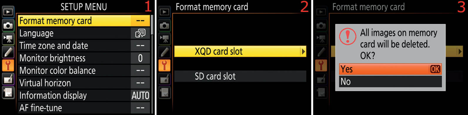
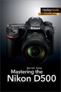
Figure 6.2A – Format memory card with Setup Menu screens
Use the following steps to format a memory card:
- 1. Select Format memory card from the Setup Menu and scroll to the right (figure 6.2A, image 1).
- 2. Next, you’ll see a screen that asks you to select the card you want to format (figure 6.2A, image 2). You have a choice of XQD card slot or SD card slot. Choose the one you want to format and scroll to the right. You’ll need to repeat this action to format the second card.
- 3. The next screen makes it very clear with an ominous-sounding message that you are about to delete all the images on the card you have selected for formatting (figure 6.2A, image 3). The screen presents a big red exclamation point and the message All images on memory card will be deleted. OK? If you have decided not to format the card, just select No and press the OK button; otherwise, Select Yes and press the OK button to start the format. After you press the OK button, you’ll see two popup messages in quick succession. The first will say Formatting memory card. A few seconds later—when the card has been successfully formatted—you’ll briefly see a final message that says Formatting complete. Then the camera switches back to the Setup Menu’s first screen. The card is now formatted and you can take lots of pictures.
Camera Button Format Method
This is the fastest method to format the memory card, and it is not very difficult. The camera defaults to formatting the primary card slot, not the secondary slot. I’ll describe how to select the secondary slot instead in the upcoming step-by-step method. Figure 6.2B shows the buttons and Control panel screens used to format the card. Notice how the two buttons are marked with the red FORMAT symbol.

Figure 6.2B – Format memory card with camera controls
To complete the memory card formatting process, follow these steps:
- 1. Notice the red FORMAT symbols beneath the Delete button (garbage can) and ISO button (figure 6.2B, images 1 and 2). These two buttons control the manual card formatting process. Hold down the Delete button and ISO button at the same time for about three seconds, until For starts flashing on the Control panel (figure 6.2B, image 3, top of panel).
- 2. While you’re still holding down the two buttons and For is flashing, you can rotate the Main command dial with your thumb to select either XQD (image 3) or SD (image 4) on the Control panel. It’s a three-finger operation, but it’s easier than it sounds.
- 3. While For is still flashing in the Control panel, release and instantly re-press the Delete button and ISO button together. During the actual formatting process, For will disappear from the top of the Control panel and you’ll see For (not flashing) where the image count normally appears in the bottom-right corner of the Control panel. Once formatting is complete, the image count will reappear on the Control panel. Do not turn your camera off during a format! When For changes back to the image count number, the format operation is complete.
- 4. You can repeat steps 1–3 for the other slot on the D500 if needed.
Settings Recommendation: Both the Setup Menu > Format memory card and camera button format methods are easy to use. Most people learn to use the button press method because it’s so fast. However, I sometimes use the Setup Menu > Format memory card method immediately after viewing images on the Monitor for verification of previous transfer to my computer. If it’s safe to format the card, I quickly switch to the Setup Menu to format because I’m already looking at the Monitor. It’s a good idea to learn how to use both methods.
Recovering from Accidental Memory Card Formatting
Interestingly, formatting a memory card doesn’t actually remove any images from the card. Instead, it removes their entries in the memory card’s file allocation table (FAT) so they can no longer be seen or found by the camera. However, you can use card recovery software to rescue most of the pictures if you do not write anything new to the card after you format it. That’s a good thing to remember in case you ever accidentally format a card with images you wanted to keep.
The manufacturer of your chosen memory card brand probably has a free image recovery utility you can download to your computer. For instance, SanDisk has recovery software called “SanDisk RescuePRO” and Lexar provides “Lexar Image Rescue.” Google your card’s brand name followed by “memory card recovery software.” Search YouTube for videos on how to use the software.
There are also several aftermarket memory card recovery products available. However, you should do some research before just downloading any old software you find; there are many scammers on the Internet. Stick with companies you know or get a recommendation from your fellow photographers on Nikonians.org!
Language
(User’s Manual: Page 304, Menu Guide: Page 125)
Language is a function that lets the camera know what language you prefer for the camera’s menus, screens, and messages. Nikon is an international company that sells cameras and lenses around the world. For that reason, the D500 can display its screens and menus in 36 languages.

Figure 6.3 – Language selection
Use the following steps to select your preferred Language (figure 6.3):
- 1. Select Language from the Setup Menu and scroll to the right (figure 6.3, image 1).
- 2. Highlight your preferred Language (figure 6.3, image 2) and press the OK button to lock in your choice.
Settings Recommendation: The camera should come preconfigured for the main language that is spoken where you live. If you prefer a different one, use this setting to select it.
Time Zone and Date
(User’s Manual: Page 304, Menu Guide: Page 126)
Time zone and date allows you to configure the Time zone, Date and time, Sync with smart device, Date format, and Daylight saving time settings for your camera.
Let’s examine how to set the various parts of Time zone and date. You may have already done this when you first received your camera. We discussed this briefly in the first chapter.
Time Zone
The Time zone screen for setting the local time zone displays a familiar world map from which you will select the area of the world where you live. Figure 6.4A shows the Time zone configuration screens. The camera displays some major city names below the Time zone map in case you don’t recognize your location.

Figure 6.4A – Time zone settings
Use the following steps to set the Time zone:
- 1. Follow the screen flow shown in figure 6.4A, images 1 and 2 (Time zone and date > Time zone) until you arrive at the third screen in the series.
- 2. To set the Time zone, use the Multi selector pad to scroll left or right until your location is under the vertical yellow bar or you see the nearest city marked with a small red dot (figure 6.4A, image 3). Press the OK button to lock in the Time zone.
Date and Time
Figure 6.4B shows the three Date and time configuration screens. The final screen allows you to select the year, month, and day (Y, M, D) and the hour, minute, and second (H, M, S).

Figure 6.4B – Date and time settings
Use the following steps to set the Date and time (figure 6.4B):
- 1. Follow the screen flow shown in figure 6.4B, images 1 and 2 (Time zone and date > Date and time) until you arrive at the third screen in the series.
- 2. Using the Multi selector pad, scroll left or right until you’ve selected the value you want to change. The Y M D settings on the left in 6.4B, image 3, are for the year, month, and day. The H M S settings on the right are for the hour, minute, and second. Scroll up or down to change each value. Press the OK button to lock in the Date and time.
Note: The international time format (ISO) is used for the D500’s time setting. To set the clock to 3:00 p.m., you must set the H and M settings to 15:00. Please refer to the following 12- to 24-Hour Time Conversion Chart.
12- to 24-Hour Time Conversion Chart
A.M. Settings: |
|
12:00 a.m. = 00:00 (midnight) |
06:00 a.m. = 06:00 |
01:00 a.m. = 01:00 |
07:00 a.m. = 07:00 |
02:00 a.m. = 02:00 |
08:00 a.m. = 08:00 |
03:00 a.m. = 03:00 |
09:00 a.m. = 09:00 |
04:00 a.m. = 04:00 |
10:00 a.m. = 10:00 |
05:00 a.m. = 05:00 |
11:00 a.m. = 11:00 |
P.M. Settings: |
|
12:00 p.m. = 12:00 (noon) |
06:00 p.m. = 18:00 |
01:00 p.m. = 13:00 |
07:00 p.m. = 19:00 |
02:00 p.m. = 14:00 |
08:00 p.m. = 20:00 |
03:00 p.m. = 15:00 |
09:00 p.m. = 21:00 |
04:00 p.m. = 16:00 |
10:00 p.m. = 22:00 |
05:00 p.m. = 17:00 |
11:00 p.m. = 23:00** |
** There is no 24:00 time (midnight). After 23:59 comes 00:00.
Note: If the clock has been reset due to a dead battery, you’ll see the word CLOCK flashing on the Control panel and a tiny, flashing, clock-face indicator will appear on the Information display.
In addition to the removable EN-EL15 Li-ion battery, the camera has a built-in clock battery that is not user-replaceable. The built-in battery charges itself from the main camera EN-EL15 battery. If CLOCK is blinking in the Control panel, it can also mean that the internal battery is exhausted and the clock has been reset.
It takes about two days of having a charged battery in the camera to fully charge the built-in clock battery. When the clock battery is fully charged, the clock will remain active without a main camera battery for up to three months.
Sync with Smart Device
The Nikon D500 can synchronize its Time, Time zone, and Daylight saving time setting with a smart device. If you regularly use your camera and smart device as a pair, you can enable this feature. Otherwise, leave it disabled.

Figure 6.4C – Enable or disable Sync with smart device
Following are the steps to configure Sync with smart device:
- 1. Follow the screen flow shown in figure 6.4C, images 1 and 2 (Time zone and date > Sync with smart device) until you arrive at the third screen in the series.
- 2. Select On or Off from the menu (figure 6.4C, image 2). Press the OK button to save the setting.
Note: This function has no effect when you are using Interval timer photography. Additionally, if a GPS device is connected to the camera and you have selected Yes for Setup Menu > Location data > External GPS device options > Set clock from satellite, the camera will use the GPS unit instead of your smart device to set the Time, Time zone, and Daylight saving time.
Date Format
Date format gives you three different ways to format the camera’s date, as follows:
- Y/M/D: Year/Month/Day (2017/12/31)
- M/D/Y: Month/Day/Year (12/31/2017)
- D/M/Y: Day/Month/Year (31/12/2017)

Figure 6.4D – Date format settings
Here are the steps to set the Date format (figure 6.4D):
- 1. Follow the screen flow shown in figure 6.4D, images 1 and 2 (Time zone and date > Date format) until you arrive at the third screen in the series.
- 2. Choose your favorite Date format from the menu (figure 6.4D, image 3). Press the OK button to lock in the setting.
Daylight Saving Time
Some areas of the world observe daylight saving time. On a specified day in spring of each year, many people set their clocks forward by one hour. Then in the fall they set them back, leading to the clever saying “spring forward, fall back.”
If you set Daylight saving time to On, the camera will move the time forward by one hour. In the fall, you will need to remember to change this setting to Off so that the camera will move the time back by one hour. Otherwise the time stamp on your images will be off by one hour for half the year.

Figure 6.4E – Daylight saving time settings
Here are the steps to enable or disable Daylight saving time (figure 6.4E):
- 1. Follow the screen flow shown in figure 6.4E, images 1 and 2 (Time zone and date > Daylight saving time) until you arrive at the third screen in the series.
- 2. Figure 6.4E, image 3, shows you the two choices for Daylight saving time: On or Off. If you select On, your camera will move the time forward by one hour from its current setting. Select Off and the camera will move the time back by one hour. This is not an automatic function. You must remember to change this setting each time daylight saving time begins and ends if you are concerned with having a correct time stamp in your picture metadata. If you don’t observe daylight saving time, just leave this set to Off and make sure the camera time matches your local time. Press the OK button to lock in the setting.
Settings Recommendation: This series includes the first settings you’ll modify when you get a brand-new D500 camera. It is important that all these items are set correctly because this information is written into the metadata of each image you make. Daylight saving time is optional, but if you use it, you must remember to change it in the fall and spring of each year so your camera’s time will match the local time. I have a reminder set up on my smartphone so that I won’t forget. When you are setting all of your clocks and watches for the semi-annual time change, just remember to set your camera’s internal clock, too.
Monitor Brightness
(User’s Manual: Page 304, Menu Guide: Page 127)
Monitor brightness is more important than many people realize. If the Monitor is too dim, you’ll have trouble seeing your images in bright light. If it is too bright, you might allow some images to be underexposed because they look fine on the Monitor. Even a seriously underexposed image may look okay on a screen that is too bright. The same goes for when you are using Live view for still images and video capture.
Additionally, you may need to adjust the Monitor brightness when you are viewing menus or the Information display in bright sunlight or for night shooting. Keeping the Monitor at the right brightness level can be very useful.
The D500 allows you to adjust the brightness of the Monitor manually. You can select from 10 levels of brightness, varying from –5 to +5. If you want to adjust this frequently, just add this function to My Menu in your camera. We will discuss how to add items to My Menu in the chapter My Menu and Recent Settings (page 488).

Figure 6.5 – Monitor brightness level adjustment
Use the following steps to adjust the brightness of the camera Monitor (figure 6.5):
- 1. Select Monitor brightness from the Setup Menu and scroll to the right (figure 6.5, image 1).
- 2. Select which of the two settings you want to adjust. Choose Menus/playback to adjust the brightness of the camera’s menu screens and for image playback (figure 6.5, image 2), or select Live view to adjust the Live view display (still images and video capture). Scroll to the right.
- 3. Use the Multi selector pad to scroll up or down through the values –5 to +5, scrolling toward the negative values to dim the Monitor or toward the positive values to brighten it (figure 6.5, image 3). Use the gray-level bars (dark to light) as a guide and adjust the brightness until you can make a distinction between the last two dark bars on the left. That may be the best setting for your camera in the current ambient light. The brightness defaults to 0 (zero), which is right in the middle. Both of the settings (Menus/playback and Live view) are adjusted in exactly the same way, so I have shown only one of them in figure 6.5. Scroll down to Live view when you are done with Menus/playback and adjust it in the same manner, if needed. Press the OK button when you’ve found the value you like best.
Note: This function does not affect the exposure of the image. It applies only to the brightness of the Monitor. However, an overly bright or dim Monitor may cause you to adjust the exposure in a detrimental way. Be careful!
Settings Recommendation: I generally leave Monitor brightness set to the 0 setting unless I need the extra brightness on a sunny day. If you choose to set your camera to a level brighter than 0, be sure to check the histogram frequently to validate your exposures. Otherwise, you may find that you are mildly underexposing images because they look fine on the Monitor due to the extra brightness. That’s one reason I examine the histogram for each important exposure. Learn to use the histogram for the best pictures!
Monitor Color Balance
(User’s Manual: Page 305, Menu Guide: Page 128)
Monitor color balance is a function that allows you to control the tint of the camera’s Monitor. If you feel the Monitor has, let’s say, a greenish tint, you can add a little bit of a complementary color to change the color to one that is more acceptable to you.
There are four color axes you can use for adjustment: green (G), amber (A), magenta (M), and blue (B). By moving the small black indicator toward a certain axis, you will add a tint for that color. You can blend the colors to arrive at nearly any tint you prefer by moving the indicator between axes.
The effect is not extremely strong, so you will not make your Monitor look garish with this function. However, the color tinting is strong enough that you can overcome any tint you perceive on the Monitor.
This effect does not change the color of the your images in any way. It only tints the color of the Monitor, allowing you to balance it against other known color sources. First let’s see how to select a sample image to display on the Monitor during color adjustment. Then we’ll see how to actually make the color balance changes.
Selecting a Sample Image
To balance the Monitor’s color, you should have an image on the Monitor that best reflects your style of photography. That way, once you adjust the colors, you will see what pleases your eye for your main style of picture making.

Figure 6.6A – Choosing a sample image for color balancing
Use the following steps to choose an appropriate sample picture for color balancing your Monitor:
- 1. Choose Monitor color balance from the Setup Menu and scroll to the right (figure 6.6A, image 1). The image you last took or viewed on the Monitor will be displayed (figure 6.6A, image 2). If this image is acceptable, then you can skip the rest of these steps and proceed with color balancing the Monitor.
- 2. To choose a different picture, you can either display it on the Monitor before selecting Monitor color balance from the Setup Menu, or you can press the Thumbnail/Playback zoom out button (third button below the MENU button) when you reach the screen shown in figure 6.6A, image 2. This will open the thumbnail screen shown in figure 6.6A, image 3. From this screen you can scroll around and select an appropriate picture for your needs. Press the OK button to select the picture you will use to balance the Monitor. (Note: While using the screen in image 3, you can select a different memory card slot and folder for your source image by pressing the Thumbnail/Playback zoom out button again.)
- 3. As seen in figure 6.6A, image 4, we are now at the screen used to actually do the Monitor color balance operation. Let’s see how in the upcoming subsection.
Changing the Monitor Color Balance
Figure 6.6B shows a sample image from a normal Monitor coloration (image 2) and four others with the tint shifted (screens 3–6).

Figure 6.6B – Changing the color balance of the camera Monitor
Use the following steps to adjust the color balance of the camera’s Monitor:
- 1. Select Monitor color balance from the Setup Menu and scroll to the right (figure 6.6B, image 1).
- 2. At the point of the red arrow in figure 6.6B, image 2, you will notice a small black square directly at the cross point of the color axes. You can move this small square directly along either of the color axis lines, or within the four color quadrants, as shown in image 3 (red arrow). Notice how the small square has been moved into the corners of the quadrants in images 3–6?
- 3. As you move the small black square around the color quadrants, you will see the tint of the small sample image change. Be sure you have selected a good sample image (see the previous subsection) so that you can choose the best balance. It may be a good idea to get an X-Rite color checker chart and take a picture of it under a neutral light source and use that picture for your sample. Remember that the ambient light will affect your perception of colors under that light, so make sure you balance the Monitor under the light source you use most often.
Note: Again, this adjustment does absolutely nothing to the pictures the camera captures. It is merely for user comfort. If the memory card contains no images, a gray rectangle will be displayed in place of the sample picture.
Settings Recommendation: Since I do not often adjust images in-camera, I will not be influenced by the way the Monitor looks. I mostly use the Monitor to make composition choices and to check the histogram. I think the Monitor on my D500 is excellent the way it is and have no need for this Monitor color balance function.
However, if I were shooting in a studio, with carefully controlled lighting, and needed to do careful color matching for a product shot, I might be more concerned about Monitor color balance.
Virtual Horizon
(User’s Manual: Page 305, Menu Guide: Page 129)
Virtual horizon is a function that allows you to level your camera when it’s on a tripod. This particular Virtual horizon function is not for Live view photography or Movie live view still image or video use. All this function does is bring up the Virtual horizon indicator on the camera’s Monitor so that you can use it to help level your camera on a tripod or other stable shooting base.
Let’s see how to use the convenient Virtual horizon to level your camera. No more need for those Accessory-shoe mounted bubble levels!

Figure 6.7 – Virtual horizon
Here are the steps to use the Virtual horizon:
- 1. Choose Virtual horizon from the Setup Menu and scroll to the right (figure 6.7, image 1).
- 2. The next two screens (figure 6.7, screens 2 and 3) show the Virtual horizon indicator. You can use it to level the camera on your tripod or even handheld if you would like. The indicator shows left and right tilts, along with forward and backward tilts. Figure 6.7, image 2, indicates that the camera is tilted to the right with the lens pointing slightly downward. Image 3 shows that the camera is level.
Note: The Live view photography and Movie live view modes have a similar, translucent version of this Virtual horizon that you can see through during live usage. That Virtual horizon is available by pressing the info button repeatedly until it shows up as one of several overlays available in either of those Live view modes.
Settings Recommendation: This is a very convenient function because it allows me to level my camera when I am using a tripod without breaking out the old Accessory-shoe bubble level. I suggest adding this function to the My Menu section of your camera. That way, you will have it available whenever you want to use it, without digging through menus to find it. We will discuss how to add items to My Menu in the chapter titled My Menu and Recent Settings (page 488).
Information Display
(User’s Manual: Page 305, Menu Guide: Page 130)
The Information display setting allows your camera to automatically sense how much ambient light there is in the area where you are shooting and adjust the color and brightness of the Information display screen accordingly. If the ambient light is bright, the color of the physical Information display screen will also be bright so it can overcome the ambient light.
To open the Information display screen, press the info button. The Information display screen shows the current shooting information.

Figure 6.8A – (1) Dark-on-light and (2) Light-on-dark display screens
Figure 6.8A shows the difference between the light and dark screens, which you can select by using one of the two Manual settings or by using Auto to allow the camera to select a screen automatically. In figure 6.8A, image 1 is the Dark-on-light screen and image 2 is the Light-on-dark screen.
Try this: With your lens cap off, your camera turned on, and nothing displayed on the rear Monitor, press the info button. If there’s dim to bright ambient light, you’ll see a white information screen with black characters. Now, go into a dark area or put your lens cap on and cover the Viewfinder eyepiece with your hand. You’ll see that anytime there is very little ambient light, the camera changes the Information display screen to light-gray characters on a dark background. This assures that you won’t be blinded when you need to see the shooting information in a dark area.
In image 2 of figure 6.8A, I have brightened the screen’s gray text considerably so that it is clear in the printed book. In real life it is much dimmer than shown here to allow you to keep your night vision.
As shown in figure 6.8B, image 2, there are two available selections for the Information display setting:
- Auto: The D500 decides through its capless lens or uncovered Viewfinder eyepiece how much ambient light there is and changes the color and contrast of the Information display screen accordingly.
- Manual: The Manual setting allows you to select the light or dark version of the Information display screen manually. If you choose Manual, you can see in figure 6.8B, image 4, that you have two options: B Dark on light (white screen) and W Light on dark (dark screen); see figure 6.8A as a reference.

Figure 6.8B – Setting Information display to Auto
Use the following steps to configure the Information display:
- 1. Select Information display from the Setup Menu and scroll to the right (figure 6.8B, image 1).
- 2. In figure 6.8B, image 2, Auto is selected. The camera will choose the light or dark screen depending on the ambient light level. If you want to use Auto, press the OK button to lock in the setting and skip the next two steps. Otherwise, proceed to the next step.
- 3. Choose B Manual and scroll to the right (figure 6.8B, image 3).
- 4. The next screen shows the B Dark on light and W Light on dark choices (figure 6.8B, image 4). Choose the look you prefer (use figure 6.8A as your reference). Press the OK button to lock in the setting. (Note: When you are using the B Manual setting, the camera will not change the screen color, even if the ambient light changes.)
Settings Recommendation: I leave Information display set to Auto because it seems to work very well at automatically selecting the proper screen for current light conditions. If you have special circumstances, you may prefer to leave the Information display set to light or dark.
AF Fine-Tune
(User’s Manual: Page 305, Menu Guide: Page 131)
The AF fine-tune function allows you to manually adjust your camera so the lens focuses where you want it to focus. There is also an additional automatic fine-tune feature available on the D500, which is discussed in the downloadable document Auto AF Fine-Tuning, available at http://rockynook.com/NikonD500.
Nikon has made provisions for keeping a table of up to 20 lenses you have fine-tuned for better focus. The idea behind fine-tuning is that you can push the focus forward or backward in small increments, with up to 20 increments in each direction.
Once you have fine-tuned the autofocus system for a particular lens and the little round AF indicator comes on in the camera’s Viewfinder, the actual focus is moved from its default position forward or backward by the amount you’ve specified in the fine-tuning operation. If your lens has a back focus problem and you move the focus a little forward, the problem is solved.
First let’s see how to access the fine-tuning system, and then we will examine each of its four subsettings in detail (figure 6.9A, image 2).

Figure 6.9A – Fine-tuning the focus of a lens
Use the following steps to start the process of fine-tuning a lens (figure 6.9A):
- 1. Choose Setup Menu > AF fine-tune (figure 6.9A, images 1 and 2).
- 2. The next four subsections show the screens to configure AF fine-tune (figures 6.9B to 6.9E). Each of the following figures continues where figure 6.9A, image 2, leaves off.
AF Fine-Tune (On/Off)

Figure 6.9B – Enabling or disabling AF fine-tune
Figure 6.9B shows the AF fine-tune (On/Off) screen and its selections. The two values you can select are as follows:
- On: This setting turns the AF fine-tune system on. Without this setting enabled, the camera focuses like a factory default D500. Set AF fine-tune (On/Off) to On if you are planning to fine-tune a lens now. Press the OK button to save the value.
- Off: This default setting disables the AF fine-tune system.
Saved Value

Figure 6.9C – Fine-tuning a lens with a Saved value
With an autofocus lens mounted, Saved value allows you to control the amount of front or back focus fine-tuning you would like to input for the listed lens. At the top left of figure 6.9C, image 2, just under the words Saved value, you’ll see the focal length of the lens that is mounted on your camera, the aperture range, and the number assigned to the lens. If you’re configuring a lens for the first time, you’ll see NO. – –. You can fine-tune a maximum of 20 lenses. After you save a lens configuration, a number will appear in place of the dashes (NO. 1 to NO. 20).
To the right of the lens information is a scale that runs from +20 on the top to –20 on the bottom. The yellow pointer on the right starts out at 0. You can move this yellow pointer up or down to change the amount of focus fine-tuning you need for this lens. Moving the pointer up on the scale pushes the focal point away from the camera, and moving it down pulls the focal point toward the camera. I set my 16–85mm lens to +5 forward focus, as shown in figure 6.9C, image 2. When you set the fine-tuning amount you need, press the OK button to save it.
Default
The Default configuration screen looks a lot like the Saved value screen, except no lens information is listed. This Default value will be applied to all AF lenses you mount on your camera. If you are convinced that your particular camera (not a lens) always has a back or front focus problem and you are not able or ready to ship it off to Nikon for repair, you can use the Default value to push the autofocus in one direction or the other until you are satisfied that your camera is focusing the way you’d like. Again, this will affect all autofocus lenses you mount on your camera.

Figure 6.9D – Setting a Default fine-tune adjustment for all lenses
As shown in figure 6.9D, image 2, to set an AF fine-tune > Default value, use the scale that runs from +20 on the top to −20 on the bottom. The yellow pointer starts at 0. You can move this yellow pointer up or down to change the amount of focus fine-tuning you need for every autofocus lens you will mount on the D500, if no value already exists in the Saved value for a particular lens (Saved value overrides Default).
Moving the pointer up on the scale pushes the focal point away from the camera (front focus), and moving it down pulls the focal point toward the camera (back focus). When you are done, press the OK button. Be careful with this setting. Most people will not use it because it applies an AF fine-tune value to any AF lens mounted on the camera, whether that lens needs fine-tuning or not.
Note: You could use this Default value as a value for any of your AF lenses that do not have a Saved value. I tested this with a different lens (not shown) by setting a Saved value of +1 for my AF-S Nikkor 24–120mm lens. While the 24–120mm lens was still mounted, I set a value of −2 for the Default value. When I removed the 24–120mm lens and mounted an AF Nikkor 60mm micro lens, the +1 in the Saved value field disappeared, but the −2 in the Default field stayed put. So it appears that you can use the Default field either for all AF lenses that have no Saved value or for a currently mounted AF lens that you want to adjust but not save a value for.
List Saved Values
Notice in figure 6.9E that there are several screens used to configure the list of saved values. List saved values helps you remember which lenses you’ve fine-tuned. It allows you to set an identification number (00–99) for a particular lens out of the 20 lenses you can register.

Figure 6.9E – Assigning an AF fine-tune lens number to one of your 20 lenses
In figure 6.9E, image 2, you can see my 16–85mm lens listed. This List saved values screen will show a list of all the lenses for which you have saved values—my camera just happens to have saved values for only one lens.
Some photographers use the last two digits of a lens’s serial number as the Saved value identification number for that lens. Use the screen shown in figure 6.9E, image 3, to select any number from 00 to 99 (figure 6.9E, image 3). Scroll up or down with the Multi selector pad to change the number in the yellow box. You will see the results of this change when you examine the Saved value screen, as shown in figure 6.9F, image 2. Instead of NO. – –, the screen in image 2 now reports NO. 1 (compare to figure 6.9C, image 2).

Figure 6.9F – NO. 1 set under Save value
You can have up to 20 lenses listed on the List saved values screen (figure 6.9E, image 2), with each lens having a different number from 00 to 99.
Auto AF Fine-Tuning
The Nikon D500 introduces a new way to set AF fine-tuning on your lenses. However, it is not controlled from the AF fine-tune function that we are discussing in this chapter. Instead, it is a process that is accomplished while the camera is in Live view photography mode.
Since this chapter is about using the menu system to adjust the camera and the Auto AF fine-tuning functionality is based on Live view photography mode, which is discussed in the downloadable document Auto AF Fine-Tuning, available at http://rockynook.com/NikonD500.
Note: With AF fine-tune enabled, the lens may not be able to focus at the minimum focus distance or at infinity. Test this carefully! Fine-tuning is not applied to any lenses when you’re using Live view photography mode. If you use teleconverters, you will need to store a value for the lens itself and the lens with the teleconverter mounted.
Settings Recommendation: AF fine-tune is good to have. If I buy a new lens and it has focus problems, I don’t keep it. Back it goes to the manufacturer for a replacement. However, if I buy a used lens or have had one long enough to go out of warranty and it later develops front or back focus problems, the camera allows me to fine-tune the autofocus for that lens.
Non-CPU Lens Data
(User’s Manual: Page 305, Menu Guide: Page 132)
Non-CPU lens data helps you use older non-CPU Nikkor lenses with your camera. Do you still have several older AI or AI-S Nikkor lenses? I do! The image quality from the older manual-focus (MF) lenses is excellent.
Since the D500 is positioned as an enthusiasts’ camera, it must have the necessary controls to use both auto focus (AF) and manual focus (MF) lenses. Many photographers on a budget use the older MF lenses to obtain professional-level image quality without having to break the bank on expensive lens purchases. You can buy excellent AI and AI-S Nikkor MF lenses on eBay for $100–$400 and with them achieve image quality that only the most expensive autofocus lenses can produce.
Lens manufacturers like Zeiss and Nikkor are still making MF lenses, and because some of them do not have a CPU (electronic chip) that communicates with the camera (i.e., they are non-CPU), it’s important to have a way to let the D500 know something about the lens in use.
This Non-CPU lens data function allows you to do exactly that. You can store information for up to nine separate non-CPU lenses within this section of the D500.
Here is an analysis of the Non-CPU lens data screen selections (figure 6.10A, image 2):
- Lens number: Using the Multi selector pad, you can scroll left or right to select one of your lenses. There are nine lens records available. When you select a Lens number here, the focal length and maximum aperture of that lens will show up in the Focal length and Maximum aperture fields. If you haven’t stored information for a particular Lens number, you’ll see double dashes (– –) in the Focal length and Maximum aperture fields.
- Focal length (mm): This field contains the actual focal length in millimeters (mm) of the lens in use. You can select focal lengths from 6 mm to 4000 mm. Hmm, I didn’t know they even made a 4000 mm lens. I want one!
- Maximum aperture: This field is for the Maximum aperture of the lens. You can enter an f-stop number from F1.2 to F22. Remember, this is for the maximum aperture only (largest opening or f-stop). When you’ve entered a maximum aperture, the camera will be able to determine the other apertures by your use of the aperture ring on the lens. (Remember those?)

Figure 6.10A – Non-CPU lens data
Use the following steps to configure (save) each of your non-CPU lenses for use with your D500:
- 1. Select Non-CPU lens data from the Setup Menu and scroll to the right (figure 6.10A, image 1).
- 2. Choose Lens number and scroll left or right until you find the number you want to use for this particular lens (figure 6.10A, image 2).
- 3. Scroll down to Focal length (mm) and scroll left or right to select the focal length of the lens (figure 6.10A, image 3). If you are configuring a non-CPU zoom lens, select the widest setting. This works because the meter will adjust for any light falloff that may occur as the lens is zoomed out.
- 4. Scroll down to Maximum aperture and scroll left or right to select the maximum aperture of the lens (figure 6.10A, image 4). If you are configuring a variable-aperture zoom lens, select the largest aperture the lens can use. This works because the meter will adjust for the variation in the aperture.
- 5. Press the OK button to store the setting.
The screen shown in figure 6.10A, image 2, allows you to either select a lens or save changes to one or all nine of your lenses. In other words, you can use the set of screens in figure 6.10A to both input and select a non-CPU lens.
When you have selected a lens for use, the Setup Menu > Non-CPU lens data selection will show the number of the lens you’ve selected. It will be in the format of NO. 1 to NO. 9. In figure 6.10A, image 1, you can see the lens selection (No. 1) at the end of the Non-CPU lens data line. That’s my beloved AI Nikkor 35mm f/2 lens!
Selecting a Non-CPU Lens with External Camera Controls
As we discussed in the previous chapter, the D500 allows you to customize several of its buttons with Button options, one of which allows you to select a non-CPU lens.
You may have only one or two non-CPU lenses, so it may be sufficient to use the Non-CPU lens data menu to select a lens. However, if you have a large selection of non-CPU lenses, you may wish Nikon had provided more than nine lens selections in the Non-CPU lens data menu.
Since I use several older manual-focus AI Nikkor lenses, I use the Custom Setting Menu to assign the setting called Choose non-CPU lens number to the Custom Setting Menu > f Controls > f1 Custom control assignment > Fn1 button + Command dial setting (page 298). This allows me to select Non-CPU lens data very quickly. I can simply hold down the Fn button and turn either of the Command dials to select one of the nine non-CPU lenses I have already registered with the camera.
Here are the steps to select a non-CPU lens using external camera controls, after making an assignment to one of the camera’s buttons (e.g., Fn1 button):
- 1. On the bottom middle of figure 6.10B, you will see n–1. That is where you choose the actual lens by its assigned number. You’ll see n–1 to n–9 scroll by as you rotate whichever Command dial is most convenient to you.
- 2. In figure 6.10B, the dark number on the top left applies to the focal length of the currently selected lens, in this case, 35mm (35).
- 3. The dark number on the top right of figure 6.10B shows the maximum aperture of the currently selected non-CPU lens (F2).
- 4. Hold down the button you’ve assigned (I use Fn1) and turn a Command dial until the number of your lens appears (n–1 to n–9), and then release the button. Now your camera knows which lens is mounted.

Figure 6.10B – Non-CPU lens data with external controls
Note: The same information seen on the Information display in figure 6.10B also shows on the top Control panel, if you prefer to use the Control panel when you change to a non-CPU lens. Either method is a quick way to change the camera’s Non-CPU lens data settings after you mount a different non-CPU lens.
Settings Recommendation: I like using the f1 Custom control assignment > Fn1 button + Command dial setting to select my non-CPU lenses (page 298). This is very fast and easy in the field. Or, you can simply use the Setup Menu > Non-CPU lens data function to select a lens via the menus. Play with both and learn how to use each. They’ll both come in handy at different times.
Clean Image Sensor
(User’s Manual: Page 305, Menu Guide: Page 133)
Clean image sensor is Nikon’s helpful answer to dust spots on your images that are due to a dirty imaging sensor. Dust is everywhere and will eventually get on your camera’s sensor. The D500 cleans the sensor by vibrating the entire sensor unit. These high-frequency vibrations will hopefully dislodge dust and make it fall off the filter so you won’t see it as spots on your pictures.
The vibration cleaning method seems to work pretty well. Of course, if sticky pollen or other moist dust gets into the camera, the vibration system won’t be able to remove it. Then it may be time for brush or wet cleaning.
Clean Now
Clean now allows you to clean the imaging sensor at any time. If you detect a dust spot, or just get nervous because you are in a dusty environment with your D500, you can simply select Clean now and the camera will execute a sensor cleaning cycle.

Figure 6.11A – Clean now screens
Use the following steps to clean the camera’s sensor immediately:
- 1. Select Clean image sensor from the Setup Menu and scroll to the right (figure 6.11A, image 1).
- 2. Select Clean now from the menu and press the OK button (figure 6.11A, image 2).
- 3. Step 2 starts the automatic cleaning process. A screen will appear that says Cleaning image sensor (figure 6.11A, image 3). When the process is complete, another screen will appear that says Done (figure 6.11A, image 4). Then the camera switches back to the Setup Menu.
Now, let’s look at how to select an active method for regular sensor cleaning.
Clean at Startup/Shutdown
For preventive dust control, many people set their cameras to clean the sensor at startup, shutdown, or both. There are four selections for startup/shutdown cleaning:
- Clean at startup
- Clean at shutdown
- Clean at startup & shutdown
- Cleaning off
These settings are self-explanatory. I find it interesting that I don’t detect any startup or shutdown delay when using the startup/shutdown cleaning modes. I can turn my camera on and immediately take a picture. The cleaning cycle seems to be very brief, or at least interruptible, in this mode.

Figure 6.11B – Clean at startup/shutdown screens
Use the following steps to choose a Clean at startup/shutdown method:
- 1. Select Clean image sensor from the Setup Menu and then scroll to the right (figure 6.11B, image 1).
- 2. Choose Clean at startup/shutdown from the menu and scroll to the right (figure 6.11B, image 2).
- 3. Select one of the four methods shown in figure 6.11B, image 3. Clean at startup & shutdown seems to be the best choice for most photographers.
- 4. Press the OK button to lock in your choice.
Nikon suggests that you hold the camera at the same angle as when you are taking pictures (bottom down) when you use these modes to clean the sensor.
Settings Recommendation: I leave my camera set to Clean at startup & shutdown. That way it will do a cleaning cycle every time I turn the camera on or off. It doesn’t seem to slow down shooting; I can still turn on the camera and immediately begin taking photographs. A little sensor cleaning in this dusty world seems like a good idea to me.
Lock Mirror Up for Cleaning
(User’s Manual: Page 305, Menu Guide: Page 133)
Lock mirror up for cleaning is for those times when the high-frequency vibration method of cleaning your D500’s sensor does not dislodge some stickier-than-normal dust. You may have to clean your sensor more aggressively.
In many cases, all that’s needed is to remove the dust with a puff of air from a dust blower. The D500 helps out by providing the Lock mirror up for cleaning mode so you can more safely blow a stubborn piece of dust off the sensor.
Using this function is much safer for blowing dust off the sensor; you can use both hands while the battery power holds the reflex mirror up and the shutter open.
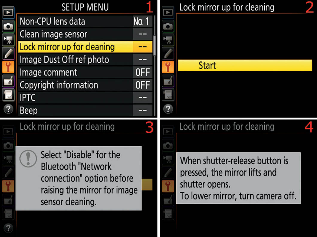
Figure 6.12A – Lock mirror up for cleaning
Use the following steps to select this mode for manual sensor cleaning:
- 1. Select Lock mirror up for cleaning from the Setup Menu and scroll to the right (figure 6.12A, image 1).
- 2. Press the OK button with Start highlighted (figure 6.12A, image 2).
- 3. If Bluetooth is enabled (default setting for the Nikon D500), you will see the screen shown in figure 6.12A, image 3. The Lock mirror up for cleaning function will not work unless you disable Bluetooth first. Go to Setup Menu > Bluetooth > Network connection and select Disable. If you do not see this screen, Bluetooth is already disabled in your camera.
When Bluetooth is disabled, you’ll see a message telling you that as soon as you press the Shutter-release button the camera will raise the mirror and open the shutter (figure 6.12A, image 3).
- 4. Remove the lens and press the Shutter-release button once. The sensor will now be exposed and ready for cleaning. Be careful not to let new dirt in while the sensor is open to air.
- 5. Use a special sensor-cleaning air blower (figure 6.12B) to blow dust off the sensor, or clean the sensor with proper fluids and pads (e.g., Eclipse fluid and PEC*PADs).
- 6. Turn the camera off and put the lens back on.
Note: Make sure you have a fresh battery in the camera because that’s what holds the shutter open for cleaning. The battery must have a charge of 60 percent or greater or the camera will not allow you to start the process (the Lock mirror up for cleaning function will be grayed out and unavailable).

Figure 6.12B – Giottos Rocket air blower from the Nikonians Photo Pro Shop
Settings Recommendation: You’ll need a good professional sensor-cleaning blower. My favorite is the Giottos Rocket air blower, which has a long tip for easy insertion (figure 6.12B). I bought my Rocket air blower from the Nikonians Photo Pro Shop (www.ppsna.com).
If an air blower fails to remove stubborn dust or pollen, you will have to either have your sensor professionally cleaned or do it yourself. Nikon states that you will void your warranty if you touch the sensor. However, many people still wet or brush clean their D500’s sensor.
If all of this makes you nervous, then send your camera off to Nikon for approved cleaning, or use a professional service. Fortunately, a few puffs of air will often remove dust too stubborn for the high-frequency vibration methods.
Image Dust Off Ref Photo
(User’s Manual: Page 306, Menu Guide: Page 134)
You may go out and do an expensive shoot only to return and find that some dust spots have appeared in the worst possible places in your images. If you immediately create an Image Dust Off ref photo, you can use it to remove the dust spots from a series of images, and then you can clean the camera’s sensor for your next shooting session.
When you use the following instructions to create the Image Dust Off ref photo, you’ll be shooting a blank, unfocused picture of a pure white or gray background. The dust spots in the image will then be readily apparent to Nikon Capture NX-D software. Yes, you must use Nikon’s free software to automatically batch-remove dust spots from a large number of images.
When you load the image(s) to be cleaned into Capture NX-D, along with the Image Dust Off ref photo, the software will use the Image Dust Off ref photo to automatically remove the dust spots in your pictures.
The position and amount of dust on the sensor may change. You should take Image Dust Off ref photos regularly and use one that was taken within one day of the photographs you wish to clean up.
Finding a Subject for the Dust-Off Reference Photo
First, you’ll need to select a featureless subject to make a photograph for the Image Dust Off ref photo. The key is to use a material that has no graininess, such as a bright, well-lit white card. I tried using plain white sheets of paper held up to a bright window, but the resulting reference photo was unsatisfactory to Capture NX-D. It gave me a message that my reference photo was too dusty when I tried to use it.
After some experimentation, I finally settled on three different subjects that seem to work well:
- A slide-viewing light table with the light turned on
- A computer monitor with a blank white word processor document
- A plain white card under bright light
All of these were bright and featureless enough to satisfy both my camera and Capture NX-D. The key is to photograph something fairly bright, but not too bright. You may need to experiment with different subjects if you don’t have a light table or computer.
Now, let’s prepare the camera for the actual reference photo.

Figure 6.13A – Image Dust Off ref photo settings
Here are the steps you’ll use to create an Image Dust Off ref photo:
- 1. Select Image Dust Off ref photo from the Setup Menu and scroll to the right (figure 6.13A, image 1).
- 2. Choose Start and press the OK button (figure 6.13A, image 2). Afterward, you’ll see the characters rEF in the Viewfinder and on the Control panel. This simply means that the camera is ready to create the image. (There is also a Clean sensor and then start selection. However, since I want to remove dust on current pictures, I won’t use this setting. It might remove the dust bunny that is imprinted on the last 500 images I just shot! I’ll clean my sensor after I get a good Image Dust Off ref photo. Choose Clean sensor and then start only if the Image Dust Off ref photo will not be used with existing images!)
- 3. When the camera is ready, hold the lens about 4 inches (10 cm) away from the blank subject. The camera will not try to autofocus during the process, which is good because you want the lens at infinity. You are not trying to take a viewable picture; you’re creating an image that shows where the dust is on the sensor. Focus is not important, and neither is minor camera shake. If you try to take the picture and the subject is not bright enough, too bright, or too grainy (not featureless), you will see the screen shown in figure 6.13B. If you are having problems with too much brightness, use a gray surface instead of white. Most of the time this error is caused by insufficient light.
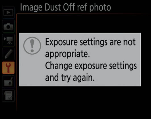
Figure 6.13B – Image Dust Off ref photo failure

Figure 6.13C – Successful Image Dust Off ref photo
If you don’t see the screen in figure 6.13B and the shutter fires, you have successfully created an Image Dust Off ref photo. You can double-check that you were successful by pressing the Playback button. If you see the image shown in figure 6.13C on your camera’s Monitor, the reference photo was captured. A file of approximately 8 MB is created on your camera’s memory card with a filename extension of .ndf instead of the normal .nef, .tif, or .jpg (an example filename is DSC-1234.NDF). This NDF file is basically a small database of the millions of clean pixels in your imaging sensor and a few dirty ones. You cannot display the Image Dust Off ref photo on your computer. It will not open in Nikon Capture NX-D or any other graphics program that I tried. It is used only as a reference by Capture NX-D when it’s time to clean images.
Where to Store the Reference Photo
Copy the NDF file from your camera’s memory card to the computer folder containing the images that have dust spots on them, the ones for which you created this Image Dust Off ref photo. You can now use Nikon Capture NX-D to remove the dust spots from all of the images represented by the Image Dust Off ref photo. Let’s examine how to do just that.
Using Capture NX-D to Remove Dust Spots
Copy the NDF file (figure 6.13C) from your camera’s memory card to the computer folder containing the images that have dust spots on them, the ones for which you created this Image Dust Off ref photo. You can use the Image Dust Off function (figure 6.13D) in Nikon Capture NX-D to remove the dust spots from all of the images represented by the Image Dust Off ref photo.
In figure 6.13D, the red-rimmed cutout in the middle is an enlargement of the Camera and Lens Corrections window in the control bar on the right side of Capture NX-D.

Figure 6.13D – Nikon Capture NX-D’s Image Dust Off function
Here are the steps to use the Image Dust Off functions in Nikon Capture NX-D to remove dust from a group of images, using an Image Dust Off ref photo (figure 6.13D):
- 1. Copy your images into a folder on your computer, along with the Image Dust Off ref photo. It is best if they are in the same folder to make sure they represent the images you recently shot. You can browse to a different folder if you want to store the dust off photo elsewhere.
- 2. Now, open Capture NX-D and use the folder browser on the left side of the screen to browse to the folder that contains your images and the dust off photo.
- 3. Press the Camera and Lens Corrections button (figure 6.13D, arrow 1) on the right side of the screen.
- 4. Select the image you want to process from the picture(s) shown in the center section of Nikon Capture NX-D. Wait a moment. When the software detects a dust off ref photo in the folder, the Change button (figure 6.13D, arrow 2) will become available.
- 5. Press the Change button. If there is only one dust off ref photo in the folder with the images, a query window will open with the following question: Do you want to use a Dust off ref photo that is in the same folder as the active image? If there is more than one dust off photo in the folder, Capture NX-D will show you all the dust off photos available and show this message: More than one suitable Dust off ref photos have been found. Please select the one you wish to use based on its shooting date and time. Choose the date-and-time-stamped dust off photo you want to use. Your choices will look like this:
2016/04/30 13:45:05 DSC-1150.ndf
2016/04/30 15:50:10 DSC-1185.ndf
- 6. Click the Yes button and Capture NX-D will process the images in the folder against the Image Dust Off ref photo, removing the dust spots from all the images in the folder. It will take some time to process the image—the computer will show a wait indicator until the picture is processed. Capture NX-D does not inform you that it is done, but when the hourglass or other wait indicator goes away the process is complete.
- 7. In the text field next to the Change button, check to see the date-and-time stamp of the Image Dust Off ref photo used to correct the image. It will look like this: “2016/04/30 15:50:10.”
Settings Recommendation: Nikon Capture NX-D is free, and it’s a good form of insurance, even if you use it for nothing more than removing dust from your images. Whenever you find yourself out in nature or shooting in an environment that might be dusty, why not create an Image Dust Off ref photo as the last photo of the day? That dust off photo may save you a lot of dust removal work. Let Capture NX-D do it for you!
Download the free Nikon Capture NX-D at the following website: http://imaging.nikon.com/lineup/microsite/capturenxd/
If for some reason the URL does not work, just Google “Download Nikon Capture NX-D” and I’m sure you will find it.
White Card Tip
Remember, all your camera needs to create an Image Dust Off ref photo is a good look at its imaging sensor so it can map the dust spots into an NDF file (ref photo file). If you get the warning screen shown in figure 6.13B that says exposure settings are not appropriate, change the exposure settings and try again with a nice bright, clean, white surface. Put the lens very close to the surface, and make sure it is not in focus. Nikon recommends less than 4 inches (10 cm). You might even want to manually set the lens to infinity if you are having problems with this. When you’ve found your favorite white or gray surface for Image Dust Off ref photos, keep it safe and use it consistently.
Image Comment
(User’s Manual: Page 306, Menu Guide: Page 136)
Image comment is a useful setting that allows you to attach a 36-character comment to each image you shoot. The comment is embedded in the picture’s internal metadata and does not show up on the image itself. I attach the comment “Photo by Darrell Young” to my images.
You could include your copyright here, even though the camera has a place to put Copyright information (see the next section), or you could insert a comment with some details about the picture series.

Figure 6.14 – Attaching an Image comment
Use the following steps to create an Image comment:
- 1. Select Image comment from the Setup Menu and scroll to the right (figure 6.14, image 1).
- 2. Select Input comment from the menu and scroll to the right (figure 6.14, image 2).
- 3. The comment entry keyboard is shown in figure 6.14, image 3. You can insert an image comment by touching the characters you want to use with your fingertip on the Monitor and they will appear in the position marked with the dark-gray cursor in the comment field (Photo by Darrell Young). You can enter up to 36 characters. You can also use the left/right arrow tip touch buttons in the top-left corner to move left and right in the comment field. To change from upper to lower case—or to access symbols, such as #—touch the Aa& button in the lower-right corner of the screen (just above the OK touch button). If you make a mistake, position the dark-gray cursor over the error and touch the Delete button at the bottom of the screen. When you’ve finished entering the comment, touch the OK button to save it. You will see the word Saved appear briefly on the Monitor. (Note: If you would prefer not to use the touch screen features, you can move the selection cursor with the Multi selector pad to highlight a character in the list below the comment field, then press the Multi selector center button to insert the character. To correct an error, hold down the Thumbnail/Playback zoom out button, use the Multi selector pad to move back and forth along the field that contains the new comment, and press the Delete button to remove the error.)
- 4. Press the OK button when you are finished entering the comment.
- 5. The camera will switch back to the Image comment screen (figure 6.14, image 4). Now you must put a check mark in the Attach comment check box so the comment will attach itself to each new image you take. To check the box, highlight the Attach comment line and scroll to the right with the Multi selector pad to place a check mark in the box.
- 6. Press the OK button to save the new comment.
Settings Recommendation: You can use this comment field for any text you want to add to the internal metadata of the image (up to 36 characters). There is another Setup Menu selection called Copyright information (see the next section) that allows you to add your personal copyright. I added basic “who took it” information here because I am worried about image theft. You may want to add other text—since the camera provides a specific Copyright information screen—such as information to identify the shoot. Remember, you are limited to 36 characters in the comment.
Copyright Information
(User’s Manual: Page 306, Menu Guide: Page 137)
Copyright information allows you to embed Artist and Copyright data into each image. Refer to figure 6.15 and use the following steps to add personal information to your camera. Your Artist name and Copyright information will then be written into the metadata of each of your images.

Figure 6.15 – Copyright information settings
Here are the steps to enter your Artist and Copyright information:
- 1. Select Copyright information from the Setup Menu and scroll to the right (figure 6.15, image 1).
- 2. Scroll down to Artist and scroll to the right (figure 6.15, image 2).
- 3. The data entry keyboard is shown in figure 6.15, image 3. You can insert your name (or other information) by touching the characters you want to use with your fingertip on the Monitor and they will appear in the position marked with the dark-gray cursor in the data entry field (Darrell Young). You can enter up to 36 characters. You can also use the left/right arrow tip touch buttons in the top-left corner to move left and right in the field. To change from upper to lower case—or to access symbols, such as #—touch the Aa& button in the lower-right corner of the screen (just above the OK touch button). If you make a mistake, position the dark-gray cursor over the error and touch the Delete button at the bottom of the screen. When you have entered your information, touch the OK button to save it. (Note: If you would prefer not to use the touch screen features, you can move the selection cursor with the Multi selector pad to highlight a character in the list below the data entry field, then press the Multi selector center button to insert the character. To correct an error, hold down the Thumbnail/Playback zoom out button, use the Multi selector pad to move back and forth along the field that contains the new comment, and press the Delete button to remove the error.)
- 4. Press the OK button when you have finished entering your information.
- 5. Now scroll down to the Copyright line on the Copyright information screen and scroll to the right (figure 6.15, image 4).
- 6. Add your name using the method and controls described in step 3 and press the OK button (figure 6.15, image 5).
- 7. Scroll up to the Attach copyright information line (figure 6.15, image 6). Initially there will be no check mark in the little box. You need to place one there. Scroll to the right with the Multi selector pad and you’ll see a tiny check mark appear in the box.
- 8. Press the OK button to save your Artist and Copyright information.
Settings Recommendation: Be sure to add your name in both the Artist and Copyright sections of this function. With so much intellectual property theft going on these days, it’s a good idea to identify each of your images as your own. Otherwise, you may post an image on Flickr or Facebook to share with friends and later find it on a billboard along the highway. With the Artist and Copyright information embedded in the image metadata, you will be able to prove that the image is yours and charge the infringer.
Embedding your personal information is not a foolproof way to identify your images because unscrupulous people may steal them and strip the metadata out of them. However, if you do find one of your images on the front page of a magazine or on someone’s website, you can at least prove that you took the image and have some legal recourse under the Digital Millennium Copyright Act (DMCA). When you’ve taken a picture, you own the copyright to that image. You must be able to prove you took it. This is one convenient way.
You’ll have even more power to protect yourself if you register your images with the US Copyright Registry at the following web address:
If you sell your camera, or loan it to someone, be sure to remove the Artist and Copyright information to prevent misuse of your name. You can either remove it manually or use Setup Menu > Reset all settings, which resets all camera settings back to their factory defaults.
IPTC
(User’s Manual: Page 306, Menu Guide: Page 138)
The IPTC function allows you to create a small database of 14 items of personal information that will be embedded into the metadata of each image you take with this camera. You may also save the IPTC database to a memory card for backup and then reload it into the camera later.
IPTC is a standard established by the International Press Telecommunications Council (IPTC), which provides guidance on the information needed when images are shared with multiple publications.
The name you give each IPTC preset you create can be a maximum of 18 characters long; it will be cut off after the 18th character. The maximum length of the information in each field of the camera’s IPTC database varies. Table 6.1 includes the database field names and how much information each field can contain.

Table 6.1 – IPTC database for the Nikon D500
Clearly, with the ability to input at least 256 characters in most fields and up to 2,000 characters in the Caption field, a camera touch screen is not the best input device to create IPTC presets.
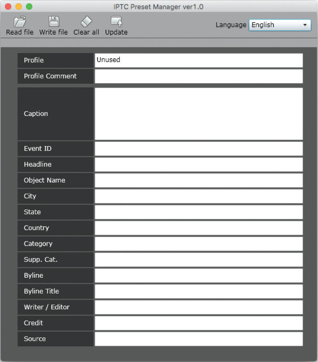
Figure 6.16A – Screenshot of Nikon’s IPTC Preset Manager software for IPTC preset creation
Nikon provides a free download of the IPTC Preset Manager software for either Mac or Windows (figure 6.16A) at:
http://downloadcenter.nikonimglib.com
You will need to type “IPTC Preset Manager” into the search field on the web page, which will take you to the final page where you can download the software.
This software will allow you to create IPTC presets that can be loaded into your camera for embedding into each image you take. I strongly suggest that you download this software and the corresponding PDF user’s manual if you are going to use the longer fields (e.g., Caption).
This chapter will cover how to enter data into the IPTC fields with the camera’s data input screen. However, unless you are using sparse information in a few of the fields, you will want the Nikon software.
Now let’s consider how to use each of the four settings in the IPTC function.

Figure 6.16B – Opening the IPTC function
Use these steps to open IPTC for use:
- 1. Choose IPTC from the Setup Menu and scroll to the right (figure 6.16B, image 1).
- 2. You will now see the IPTC screen which contains four settings (figure 6.16B, image 2). Choose one and scroll to the right to configure its subsettings.
Let’s examine the four settings inside the IPTC function and see how to use their subsettings.
Edit/Save
The Edit/save setting allows you to Edit (create), Rename, and Copy IPTC presets, all within the Nikon D500 itself. (Note: These methods are not for the Nikon IPTC Preset Manager software.) Let’s examine each of the subsettings within Edit/save.
Edit or Create an IPTC Preset
Editing, or creating, an IPTC preset allows you to create a new preset and fill in important IPTC information in the database field. It also lets you edit an existing IPTC preset so that you can modify current text fields in the database. Following are the screens and steps to edit or create an IPTC database record.

Figure 6.16C – Editing or creating an IPTC preset
Use the following steps to edit or create an IPTC preset:
- 1. Figure 6.16C begins where figure 6.16B ends. Choose Edit/save from the IPTC menu and scroll to the right (figure 6.16C, image 1).
- 2. Highlight one of the 10 IPTC preset memory locations (P-1 to P-10) and scroll to the right (figure 6.16C, image 2).
- 3. To create a new IPTC preset you must use the Rename subsetting (figure 6.16C, image 3). Select Rename and scroll to the right.
- 4. The data entry screen is shown in figure 6.16C, image 4. You can insert the name of your new IPTC preset by touching the characters with your fingertip on the Monitor and they will appear in the position marked with the dark-gray cursor in the data entry field (Darrell Young). You can enter up to 18 characters. You can also use the left/right arrow tip touch buttons in the top left corner to move left and right in the field. To change from upper to lower case—or to access symbols, such as #—touch the Aa& button in the lower-right corner of the screen (just above the OK touch button). If you make a mistake, position the dark-gray cursor over the error and touch the Delete button at the bottom of the screen. When you have entered your information, touch the OK touch button (or use the physical OK button) to save it. (Note: If you would prefer not to use the touch screen features, you can move the selection cursor with the Multi selector pad to highlight a character in the list below the data entry field, then press the Multi selector center button to insert the character. To correct an error, hold down the Thumbnail/Playback zoom out button, use the Multi selector pad to move back and forth along the field that contains the new comment, and press the Delete button to remove the error. Press the OK button when you have finished entering your information.)
- 5. Rename: To rename an existing IPTC preset, select the preset from the preset list shown in figure 6.16C, image 2—instead of selecting an Unused (P-1 to P-10) storage location—then select Rename in figure 6.16C, image 3, and repeat step 4.

Figure 6.16D – Copying an existing IPTC preset to a P-1 to P-10 location
- 6. Copy: To copy an existing IPTC preset from a current P-location (P-1 to P-10) to a new P-location in the preset list, you will need to use a couple of camera buttons (marked with the red A and B in figure 6.16D, image 1). The red A (Confirm) represents the Thumbnail/Playback zoom out button (third button down from the MENU button). The red B (Copy) represents the Playback zoom in button (second down from the MENU button). Please note that the screen shown in figure 6.16D, image 1, is the same as the screen shown in figure 6.16C, image 2, except that the latter has several IPTC presets already saved in some of the P-locations. Instead of creating or editing a preset, like we did in steps 1–5, we will copy one of the presets to a new location and give it a new name in the process. Here are the steps:
- a. To start copying a preset: Highlight an existing preset (e.g., Blue Ridge Parkway) as shown in figure 6.16D, image 1. Note that there are two button symbols at the bottom of the screen in image 1 (A and B). When you press the A-Confirm (Thumbnail/Playback zoom out) button you will be presented with some of the contents from the IPTC preset you have highlighted (figure 6.16D, image 2). The A screen (image 2) in my example shows the contents of my Blue Ridge Parkway preset. This screen allows you to review the highlighted preset so you can validate that it is the one you want to copy. Scroll up or down with the Multi selector pad to view all the database fields in the preset.
- b. To finish copying a preset: After you have verified that the highlighted preset is the one you want to copy, press the B-Copy (Playback zoom in) button in figure 6.16D, image 1, and you will see the B screen (image 3). It looks the same as the preset screen in image 1, except that the heading has changed from Select preset to edit or save (image 1) to Select destination (image 3). I have selected the P-4 Unused location (highlighted in yellow) as the destination location for a copy of the original P-3 Blue Ridge Parkway preset. The camera has created a copy of the P-3 preset in its memory and is ready to rename it as a brand-new preset to be saved in location P-4. To rename the preset, scroll to the right and the screen in figure 6.16D, image 4, will appear.
- c. To rename the newly copied preset: Use the instructions in step 4 to rename the brand-new copy of the Blue Ridge Parkway preset. I chose to name the copy Blue Ridge Pkwy 2. To save the copied preset to the P-4 location, touch the OK touch button on the screen or press the physical OK button on the camera. You will briefly see the word Saved pop up on the screen and the camera will switch back to the preset list. The P-3 preset has now been copied and saved to the P-4 storage location (figure 6.16D, image 6). Note: The camera will not force you to rename a copy of an original preset. You can use identical names because the presets have different storage locations. However, it seems a bit counterproductive to have two presets with exactly the same name. You would have to use the A-Confirm (Thumbnail/Playback zoom out) button every time you selected one of the two presets to determine if there are any differences.
Now let’s consider how to delete a preset that we no longer need.
Delete
If you no longer need a particular IPTC preset, you can remove it from your camera’s list of presets and open up that P-location (P-1 to P-10) for another preset you may want to create.

Figure 6.16E – Deleting an IPTC preset
Use the following steps to remove an existing IPTC preset from the camera:
- 1. Follow the screen flow shown in figure 6.16E, images 1 and 2 (IPTC > Delete) until you arrive at the third screen in the series.
- 2. Highlight the IPTC preset you want to delete and scroll to the right (figure 6.16E, image 3).
- 3. Select Yes from the screen that asks Delete IPTC preset?, validate that the screen is showing the correct preset (e.g., Smoky Mountains), and press the OK button to delete the preset.
Auto Embed During Shooting
Now that you have created some excellent IPTC presets, you may want to start using them. Let’s see how to automatically embed the information from a particular IPTC preset into the metadata of a series of images.

Figure 6.16F – Embedding an IPTC preset into a series of images
Use the following steps to enable auto embedding, which will insert specific IPTC information into the metadata of all images you take until you disable embedding:
- 1. Follow the screen flow shown in figure 6.16F, images 1 and 2 (IPTC > Auto embed during shooting), until you arrive at the third screen in the series.
- 2. Highlight one of the IPTC presets (e.g., Darrell Young) and press the OK button to have the camera automatically embed the selected preset into all future images (figure 6.16F, image 3). You can turn off automatic embedding off by selecting Off at the top of the preset list (image 3).
Settings Recommendation: I have the camera embed the preset that contains my name all of the time. That way, I am embedding personal information into all images I take. However, when I go to specific geographical areas to take my nature stock photos, I will use a customized IPTC preset with that location’s name (e.g., Blue Ridge Parkway).
Load/Save
This setting lets you save IPTC presets to your camera’s memory card so you can import them into other compatible Nikons or back them up on your computer. You can also load previously stored IPTC presets back into your D500.
When you save an IPTC preset to a memory card, the camera will create a folder named NIKON on the memory card. Within that folder it will create another folder named IPTC, which will be used to store and retrieve IPTC presets.
IPTC presets vary in size, depending on the amount of text in each preset. An empty preset is about 409 bytes. Of course, since text requires little storage space, IPTC presets will remain rather small, meaning you could store many of them without seriously impacting overall card capacity.
Each IPTC preset is given a file name like NCIPTC01.NMS, in case you want to back it up to your computer. Here is the full file path to an IPTC preset file stored on a memory card: NIKON/IPTC/NCIPTC01.NMS
Now let’s examine how to save and load IPTC presets.
Copy to Card
Since we need to save some IPTC presets to a memory card before we try to load them back into the camera, we’re not going to follow the exact menu order under the Load/save setting. We’ll examine the Copy to card subsetting first.

Figure 6.16G – Use Copy to card to save an IPTC preset to a memory card.
Use the following steps to copy an IPTC preset to a camera memory card:
- 1. Follow the screen flow shown in figure 6.16G, images 1 to 3 (IPTC > Load/save > Copy to card) until you arrive at the fourth screen in the series.
- 2. Highlight the IPTC preset (e.g., Cade’s Cove) that you want to copy to the memory card and scroll to the right (figure 6.16G, image 4).
- 3. You can now choose an Unused P-location (P-1 to P-10) or select an occupied P-location if you want to overwrite an old IPTC preset. In figure 6.16G, image 5, I chose an Unused location (P-5). Scroll to the right if you chose an Unused location. If you choose to overwrite a location that already contains an IPTC preset, the camera will ask for your permission to do so with a popup message that says Overwrite? Yes/No. Highlight Yes and press the OK button to overwrite an existing preset.
- 4. The final screen will show before the file is saved (figure 6.16G, image 6). On this screen you can validate that the name is correct or use the touch-screen system to rename the IPTC preset before saving it. Press the OK button to save the preset to the memory card.
Copy to Camera
Now that we have saved some IPTC presets to the memory card (in the previous subsection), let’s see how to copy an IPTC preset from a memory card to the camera (Copy to camera).
Use the following steps to copy an IPTC preset from a memory card into the camera’s list of IPTC presets:
- 1. Follow the screen flow shown in figure 6.16H, images 1 to 3 (IPTC > Load/save > Copy to camera) until you arrive at the fourth screen in the series.
- 2. Highlight the IPTC preset you want to copy from your memory card to your camera and scroll to the right (figure 6.16H, image 4).

Figure 6.16H – Use Copy to camera to copy an IPTC preset from a memory card to the D500.
- 3. You can now choose an Unused P-location (P-1 to P-10) or select an occupied P-location if you want to overwrite an old IPTC preset. In figure 6.16H, image 5, I chose an Unused location (P-4). Scroll to the right if you chose an Unused location. If you choose to overwrite a location that already contains an IPTC preset, the camera will ask for your permission to do so with a popup message that says This IPTC preset is in use. Overwrite? Yes/No. Highlight Yes and press the OK button to overwrite an existing preset.
- 4. The final screen will show before the file is saved (figure 6.16H, image 6). On this screen you can validate that the name is correct or use the touch-screen system to rename the IPTC preset before saving it. Press the OK button to save the preset to the camera.
Beep
(User’s Manual: Page 306, Menu Guide: Page 141)
The Beep setting allows your camera to make a beeping sound (if enabled) to alert you during the following events:
- Focus lock while in Single-servo AF (AF-S) mode
- Focus lock while in Live view mode
- Countdown in Self-timer mode operations
- At the end of Time-lapse movie
- If you try to take a picture with the memory card locked
- While using Mirror-up (Mup) mode, if you press the Shutter-release button a second time to release the shutter
- When the touch screen is used for keyboard entry
You can set the camera to beep with a high- or low-pitched tone, and you can adjust the volume of the beep—or you can turn the beep sound off. When Beep is active, you’ll see a little musical note displayed in the Information display on the Monitor, and of course, you will hear the camera beeping when you do the things in the list.
First let’s examine how to set the Volume or disable Beep. It defaults to Off in the D500.

Figure 6.17A – Choosing a Volume level for the camera’s Beep
Use the following steps to select one of the Beep Volume choices:
- 1. Follow the screen flow shown in figure 6.17A, images 1 and 2 (Beep > Volume), until you arrive at the third screen in the series.
- 2. Choose one of the four options from the list (1, 2, 3, or Off). In figure 6.17A, image 3, Off is selected (factory default). You will hear a sample beep for each volume level as you choose it. The level 1 beep is rather quiet, so you may not hear it unless you hold your ear close to the camera, whereas the level 3 beep is almost obnoxiously loud. Press the OK button to lock in the setting.
Next, let’s consider the screens and steps to select a pitch for the beep.

Figure 6.17B – Choosing a Pitch for the camera’s Beep
Use the following steps to select a Beep Pitch:
- 1. Follow the screen flow shown in figure 6.17B, images 1 and 2 (Beep > Pitch), until you arrive at the third screen in the series.
- 2. Choose one of the two options from the list (High or Low). In figure 6.17B, image 3, Low is selected. You will hear a sample beep in each pitch when you choose it. Press the OK button to lock in the setting.
Settings Recommendation: I keep Beep turned Off on my D500. If I were using my camera in a quiet area, why would I want it beeping and disturbing those around me?
However, you might want the reassurance of hearing a beep when AF has been confirmed or when the Self-timer is counting down. If so, turn it on. The Self-timer lamp flashes during Self-timer operations, so I generally use that instead of Beep.
By the way, Beep is automatically disabled when you’re using the Q, or Quiet, shutter-release mode on the Release mode dial, regardless of how this setting is configured.
Touch Controls
(User’s Manual: Page 306, Menu Guide: Page 142)
The Nikon D500 has a convenient touch control capability that lets you use your fingertip to enter the names of various items, select touch controls on the monitor, swipe from one picture or video to another when viewing them on the Monitor, and press Play on displayed videos.
The Touch controls function allows you to enable or disable the touch control feature, as well as set the swipe (flick) direction for when you are viewing pictures. Let’s examine how to configure the two parts of the Touch controls system.
Enabling or Disabling the Touch Controls System

Figure 6.18A – Enabling or disabling the camera Touch controls system
- 1. Follow the screen flow shown in figure 6.18A, images 1 and 2 (Touch controls > Enable/disable touch controls), until you arrive at the third screen in the series.
- 2. Select Enable or Disable from the menu (figure 6.18A, image 3), and press the OK button to lock in the setting. The factory default is Enable.
Settings Recommendation: I have been using the Touch controls system quite often as I work through the many functions it supports. I find it quite convenient when entering data, compared to fiddling around with physical buttons and pads.
The only gripe I have is that I would prefer a QWERTY keyboard layout instead of a series of letters, just because I’m used to using that layout on my smartphone (texting). Why couldn’t Nikon make a keyboard that looks more like my iPhone’s keyboard, including the touch button locations and functionality, so that I (you) don’t have to search for each character? Aren’t we all used to using tiny smart phone keyboards by now? Why have an Aa& touch button instead of ↑ and 123?
Otherwise, the Touch controls system works well and is easy to use. I think our smart cameras are finally joining the digital world.
Changing Swipe (Flick) Direction for Viewing Images

Figure 6.18B – Setting the direction of the finger swipe when viewing images on the Monitor
- 1. Follow the screen flow shown in figure 6.18B, images 1 and 2 (Touch controls > Full-frame playback flicks), until you arrive at the third screen in the series.
- 2. Select either Left←Right or Left→Right from the menu (figure 6.18B, image 3). Press the OK button to lock in the setting.
Settings Recommendation: I’ve been scratching my head trying to figure out why someone would want the swipe (flick) to work in the opposite direction of what smartphone users have trained their muscle memory to expect. When I am swiping on my camera’s Monitor, I expect to see the next image by swiping from right to left, just like on my iPhone.
However, if you would prefer the swipe to work in the opposite direction, choosing Left→Right will fix you right up. Then, when you swipe right to left, the camera will display the previous picture instead of the next picture.
HDMI
(User’s Manual: Page 306, Menu Guide: Page 142)
HDMI (high-definition multimedia interface) allows you to display your images and video on a high-definition television (HDTV), external video monitor, or computer monitor with an HDMI connection. You can also use the HDMI port to stream clean, uncompressed, broadcast-quality video to an external video recording device, such as one of the recorders found on www.Atomos.com.
You’ll need an HDMI Type-A to HDMI Type-C cable, which is not included with the camera but is available from many electronics stores. This cable is also known as a mini-HDMI–to–HDMI A/V HD cable.

Figure 6.19A – Type-A and Type-C HDMI cable ends
Figure 6.19A gives you a close-up look at both ends of the cable. The smaller end (mini-HDMI Type-C) goes into the HDMI port under the rubber flap on your camera, and the other end (HDMI Type-A) plugs into your HD device.
The HDMI setting has two options, Output resolution and Advanced, which we’ll discuss next.
Output Resolution
You can select one of the following formats for output to your HDMI device:
- Auto (default): This allows the camera to select the most appropriate format for displaying your image on the currently connected device
- 2160p (progressive): 3840 × 2160 progressive UHD format
- 1080p (progressive): 1920 × 1080 progressive Full HD format
- 1080i (interlaced): 1920 × 1080 interlaced Full HD format
- 720p (progressive): 1280 × 720 progressive HD format
- 576p (progressive): 720 × 576 progressive SD format
- 480p (progressive): 640 × 480 progressive SD format
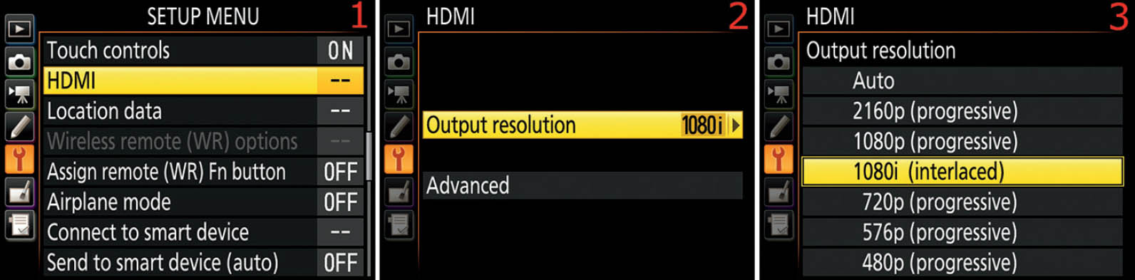
Figure 6.19B – Selecting an HDMI Output resolution
Use the following steps to select an Output resolution (figure 6.19B):
- 1. Follow the screen flow shown in figure 6.19B, images 1 and 2 (HDMI > Output resolution), until you arrive at the third screen in the series.
- 2. Select one of the six output resolutions or Auto (figure 6.19B, image 3). I chose 1080i (interlaced) as an example. You might want to try Auto at first to see if the camera and display device will interface by themselves. If not, read the user’s manual for the display device to find out what output resolution works best with it. Set the camera accordingly. Press the OK button to lock in your selection.
Advanced
With the large variety of display and recording devices available, your camera has to deal with all sorts of video standards. Here is a brief list of the controls available for modifying the HDMI video output:
- Output range controls how color is displayed on the receiving device. You can limit the RGB video output to a Limited range of 16 to 235, or a Full range of 0 to 255. Or you can select Auto to let the camera decide for you.
- Output display size sets frame coverage for horizontal and vertical output. Your choices are 95% or 100%. This allows you to fit the video display on monitors with a reduced display area or a full display area.
- Live view on-screen display controls whether the camera outputs clean HDMI video or video with the shooting information overlaid on the video signal (e.g., aperture, shutter speed, ISO).
- Dual Monitor allows you to mirror the video stream from the HDMI port on the camera’s Monitor, in addition to an external monitor. This uses more battery power but gives you dual monitors.
Let’s examine each setting on the Advanced menu in more detail.

Figure 6.19C – Using Advanced HDMI settings
Use the following steps to open the Advanced menu (figure 6.19C):
- 1. Follow the screen flow shown in figure 6.19C, images 1 and 2 (HDMI > Advanced), until you arrive at the third screen in the series.
- 2. Select one of the four settings from the Advanced menu and scroll to the right (figure 6.19C, image 3).
- 3. Refer to figures 6.19D through 6.19G for details on the configuration of each Advanced item.
Output Range
Output range allows you to adjust the level of colors sent to a recording or display device. When you are outputting video to a device, such as an HDTV or recorder, the device may not accept normal Full range RGB with a color range of 0 to 255 correctly. Some devices accept only Limited range RGB input in the range of 16 to 235 color levels (YCbCr). If you try to send Full range RGB video output to a Limited range YCbCr device, you may end up with washed-out, grayish blacks and blown-out, featureless whites.
The solution is to match the correct output to the correct device type. If you see the problems just described when the camera is set to Full range (RGB), try the Limited range (YCbCr) setting instead. Or, you could try the Auto setting to see if the camera can detect what the display or recording device requires.
We will discuss this in deeper detail in the upcoming chapter Movie Live View (page 591).

Figure 6.19D – Selecting an Output range
Use the following steps to select Full range or Limited range output (figure 6.19D continues from figure 6.19C):
- 1. Select Output range from the Advanced menu and scroll to the right (figure 6.19D, image 1).
- 2. Choose Auto, Limited range, or Full range from the Output range menu. Auto (factory default) is selected in figure 6.19D, image 2. Press the OK button to select the Output range.
Output Display Size
At times, the Output display size may not match the display device well. In that case, you can reduce the Output display size from 100% to 95% to help the display fit better. If you plug your D500 into your HDTV and find that the output on the TV is a little bit too tall, you can change Output display size to 95% and it will fit perfectly. You can do this on the fly while viewing the live output on an HDTV.

Figure 6.19E – Changing the Output display size
Use the following steps to change the Output display size (figure 6.19E continues from figure 6.19C):
- 1. Select Output display size from the Advanced menu and scroll to the right (figure 6.19E, image 1).
- 2. Choose 95% or 100% from the Output display size menu. 100% (factory default) is selected in figure 6.19E, image 2. Press the OK button to lock in the Output display size.
Live View On-Screen Display
Live view on-screen display is the setting you’ll use when you want the streaming video output from the camera to have no shooting information overlays. Here are your two choices:
- Off: When Live view on-screen display is set to Off, the camera outputs a clean, uncompressed, 4:2:2 video stream with no distracting overlays.
- On: If you choose On, the camera will stream video with the same information you see on the Monitor, which may include shooting information such as aperture, shutter speed, ISO sensitivity, metering mode, gridlines, sound input levels, focus mode, Picture Control type, image size, image quality, image area, and so forth.
If you want to output clean, overlay-free, uncompressed, broadcast-quality video, choose Off for this setting.

Figure 6.19F – Choosing a Live view on-screen display mode
Use the following steps to change the Live view on-screen display, enabling or disabling pure video output (figure 6.19F continues from figure 6.19C):
- 1. Select Live view on-screen display from the Advanced menu and scroll to the right (figure 6.19F, image 1).
- 2. Select On or Off from the Live view on-screen display menu. Off (factory default) is selected in figure 6.19F, image 2. Press the OK button to lock in the setting.
We have examined only how to select and set the modes, with some basic reasons why we decided to use each mode. Shooting video is new to many photographers, so the chapter Movie Live View (page 591) will provide much-needed detail.
Dual Monitor
The Nikon D500 can send an HDMI video output signal to two monitors simultaneously—an external monitor and the Monitor on the camera. You can use a basic external monitor merely to see the output more clearly, or you can use an external video recorder (www.Atomos.com). Unlike its ancestors, the D500 can also show the same signal you see on the external monitor on the camera’s Monitor. Let’s see how it works.

Figure 6.19G – Use an external monitor and the camera’s Monitor
Use the following steps to enable or disable the Dual monitor capability built into the Nikon D500 (figure 6.19G continues from figure 6.19C):
- 1. Please notice at the arrow in figure 6.19G, image 1, that the Dual monitor feature defaults to On. Therefore, if you want to use dual monitors, the camera is ready immediately. Also, please notice that in image 1 Live view on-screen display is set to Off, meaning that the camera will output no shooting information overlays with the clean video signal. But what if you want to disable the Dual monitor capability? It is grayed out and unavailable when Live view on-screen display is set to Off.
- 2. You can disable Dual monitor, but first you have to set Live view on-screen display to On. Once you have done so, the Dual monitor function becomes available. Figure 6.19G, image 2, shows that Live view on-screen display is enabled (On), which also makes the Dual monitor feature available for selection. To enable or disable Dual monitor, choose Dual monitor and scroll to the right.
- 3. Select On or Off from the menu, which enables or disables Dual monitor. Press the OK button to lock in the Dual monitor setting. Once you have chosen a Dual monitor setting, please revisit the Live view on-screen display setting to make sure it is Off if you want clean video output for your external video recorder. Use the step-by-step method attached to figure 6.19F (previous subsection) to change the Live view on-screen display back to the way you want it.
Settings Recommendation: Please spend some time familiarizing yourself with the features of this function. Later in this book, in the chapter titled Movie Live View (page 591), you will need to have an understanding of using HDMI output. The D500 camera has enhanced video output compared to its predecessors. Therefore, if you have not been fond of video with an HD-SLR in the past, you may want to reconsider now that you are using the Nikon D500. It is a portable home movie studio, with full UHD (4K) broadcast-quality commercial capabilities!
Location Data
(User’s Manual: Page 307, Menu Guide: Page 143)
The Location data function allows you to geotag your images with global positioning system (GPS) location data. It provides an easy-to-use interface for various GPS and smart devices.
Now when you shoot a spectacular travel image, you can rest assured that you’ll be able to find that exact spot next year. With the Nikon GP-1 or GP-1A GPS units (or an aftermarket brand), or your smart device, the D500 will record the following GPS information about your location into the metadata of each image:
- Latitude
- Longitude
- Altitude
- Heading (aftermarket only)
- UTC (time)
Using a Smart Device for GPS
The Nikon D500 allows you to pull GPS data from your smart device (e.g., your smartphone or tablet). To use the SnapBridge app to transfer GPS data to your D500, the following services must be enabled:
Smart Device
- Bluetooth
- Location services (for GPS use)
Nikon D500
- Bluetooth (page 432)
- Location data (this section) As the list shows, you must first enable Bluetooth and location services on your smart device. You also need to enable Bluetooth (page 432) and Location data (the function we are discussing) on your D500. Use the following menu command to enable Bluetooth on your camera: Setup Menu > Bluetooth > Network connection (i.e., set it to On).
Bluetooth is necessary for the smart device and camera to communicate for GPS data transmission (Wi-Fi is not required for GPS data transfer). Location services must be enabled on your smart device, or it will not enable GPS and no positioning data will be available for transfer to the camera.
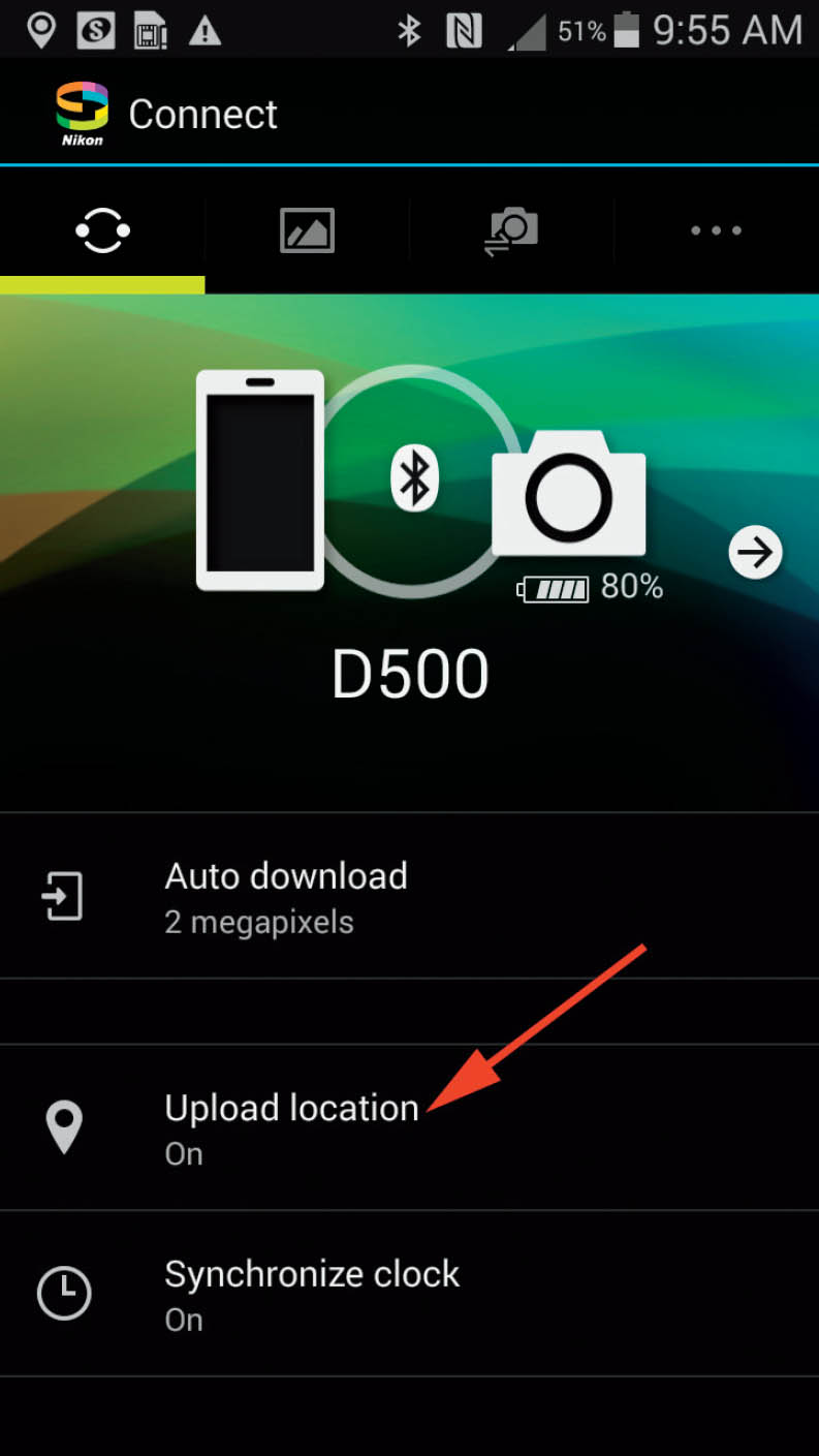
Figure 6.20A – Smartphone SnapBridge app screen with Upload location set to On
Figure 6.20A shows the SnapBridge app on my smartphone. You can see that Upload location is set to On and my smartphone is connected to my D500 via Bluetooth. The camera will acquire GPS location data from the smart device, refreshing it approximately every five minutes (the time varies by a few seconds).
The Bluetooth connection with SnapBridge seems to use significant battery power, so it’s a good idea to have extra batteries available when using SnapBridge for GPS.
Note: You may want to enable the Synchronize clock setting (just below Upload location on the SnapBridge screen shown in figure 6.20A). When the Synchronize clock setting is enabled, the D500 can receive time and date information from the smart device while pictures are being taken. You must enable (set to On) Setup Menu > Time zone and date > Sync with smart device to allow the camera to accept time and date from the SnapBridge app.
Downloading GPS Location Data from a Smart Device
Let’s examine how to set the camera so that it is ready to receive GPS Location data from the SnapBridge app on your smart device. As mentioned previously, you must first enable Bluetooth and make a connection between your smart device and the camera. The process of making a Bluetooth connection is discussed under the Bluetooth heading later in this chapter (page 432). Review that material, make a Bluetooth connection (Wi-Fi not required) between the camera and SnapBridge, and then return here.
If you do not have a good connection, the first menu item under Location data, Download from smart device (shown in figure 6.20B, image 2), will be grayed out and unavailable. Once the camera and SnapBridge are connected via Bluetooth, Download from smart device will become available.

Figure 6.20B – Enabling the Location data (GPS) system for SnapBridge synchronization
Use the following steps to enable GPS Location data to flow from your smart device to your camera:
- 1. Follow the screen flow shown in figure 6.20B, images 1 and 2 (Location data > Download from smart device), until you arrive at the third screen in the series.
- 2. Choose Yes to enable or No to disable the flow of GPS Location data between the smart device (SnapBridge app) and your D500. Press the OK button to lock in the setting.
You can tell when the camera and SnapBridge app are communicating by examining the Position screen shown in figure 6.20C, image 2. It will show GPS Location data once a connection is made.

Figure 6.20C – GPS Location data Position screen
Notice that the SnapBridge app did not give me accurate Altitude or Heading information (figure 6.20C, image 2). According to my Nikon GP-1 GPS unit, my actual altitude is 320m. Maybe Nikon will improve the SnapBridge app later on, or this could just be a limitation of my current smartphone. Check your smartphone’s output to see if it gives better GPS Altitude and Heading information.
Next let’s consider how to use an external GPS unit instead of the SnapBridge app to get GPS Location data.
Note: If you are using a smart device for GPS and an external GPS unit at the same time, the D500 will use the GPS Location data from the external GPS unit instead of the smart device.
Using an External GPS Unit
If you prefer to use an external GPS unit instead of a smart device to obtain GPS Location data, the D500 gives you that option.
The GPS unit you choose must be compatible with the National Marine Electronics Association NMEA0183 data format version 2.01 or 3.01.
I use a Nikon GP-1 GPS unit often on my D500. It’s small, easy to carry and store, and works very well. I have other Nikon DSLRs, too, and this GPS unit works on all of them with the proper cables. The newer Nikon GP-1A GPS unit is also fully compatible with the D500.
In figure 6.20D, you can see a Nikon GP-1 attached to the camera’s Accessory shoe. You can also see the GP1-CA10 cable plugged into the 10-pin connector on the front of the camera. I deliberately put the curl in the cable to keep it from sticking out awkwardly.

Figure 6.20D – Nikon D500 with a Nikon GP-1 GPS unit, GP1-CA10 cable, and MC-DC2 remote release cable
The GP1-CA10 cable will interface with Nikon cameras that have a 10-pin port on the body, including the following Nikon cameras: D200, D300, D300S, D500, D700, D800, D800E, D810, D2X, D3, D3S, D3X, D4, D4S, and D5.
The GP-1 GPS unit also comes with a GP1-CA90 cable to interface with Nikon cameras, including the following models: D3000, D3100, D3200, D3300, D5000, D5100, D5200, D5300, D5500, D90, D7000, D7100, D7200, D600, D610, Df, and D750. So it is a useful device for almost any of your newer Nikons.
You can also get an optional Nikon MC-DC2 remote release cable that plugs directly into the GP-1 GPS unit for hands-off, vibration-free photography. The MC-DC2 remote release cable can be used to fire the shutter on any Nikon DSLR that can interface with the GP-1 or GP-1A GPS unit. You can see the MC-DC2 remote release cable on the left side of the camera in figure 6.20D. It is plugged into the GP-1 GPS unit on the opposite side of where the GP1-CA10 cable plugs in. The mentioned cables are compatible with both the Nikon GP-1 and GP-1A GPS units.
Note: The Nikon GP-1 and GP-1A GPS units do not have a built-in digital compass, so they will not report heading information to the camera. Other GPS units do have the built-in compass and will report the heading. If that is important to you, please investigate the Geotagger Pro GPS unit at this web page:
Preparing the Camera for GPS Usage
You’ll use several screens when setting up the D500 for GPS use. First, you have to make a decision about whether the exposure meter always remains active when a GPS unit is plugged into the camera. While the GPS unit is plugged in, the camera’s exposure meter must be active to record GPS data to the image. You should do one of two things:
- Set the exposure meter to stay on for the entire time that a GPS unit is plugged in. This will increase battery drain, but it keeps the GPS locked to the satellites (no seeking time).
- Press the Shutter-release button halfway down to activate the exposure meter before finishing the exposure. If you push the Shutter-release button down quickly and the GPS is not active and locked, it won’t record GPS data to the image. The meter must be on before the GPS will seek satellites.
Standby Timer
Figure 6.20E shows the screens used to set the meter to either stay on the entire time the GPS is connected or shut down after the Custom Setting Menu > c Timers/AE lock > c2 Standby timer delay expires.
Interestingly, the Location data setting also has a subsetting named Standby timer, which controls whether the GPS unit stays on continuously or shuts down when the timeout set in Custom setting c2 Standby timer occurs.
The Custom setting c2 Standby timer function is for all aspects of the camera. The Location data’s Standby timer subsetting applies only to an attached GPS unit.
Here’s what each setting in Standby timer does:
- Enable (default): The meter turns off after the Custom Setting Menu > c Timers/AE lock > c2 Standby timer delay expires (the default is 6 seconds). GPS data will be recorded only when the exposure meter is active, so allow some time for the GPS unit to reacquire a satellite signal before taking a picture. This is hard to do when c2 Standby timer is set to the default 6 seconds (6 s). You pretty much have to stand around with your finger on the Shutter-release button trying to keep the meter active. I suggest using Disable.
- Disable: The exposure meter stays on the entire time a GPS unit is connected. As long as you have a good GPS signal, you will be able to record GPS data at any time. This is the preferred setting for using the GPS for continuous shooting. It does use extra battery life, so you may want to carry multiple batteries if you’re going to shoot all day. Turn the camera off between locations.

Figure 6.20E – Setting an Auto meter off delay for GPS usage
Here are the steps to configure the External GPS device options for the Standby timer delay:
- 1. Follow the screen flow shown in figure 6.20E, images 1 to 3 (Location data > External GPS device options > Standby timer) until you arrive at the fourth screen in the series.
- 2. Select Enable or Disable (figure 6.20E, image 4). Use Disable for more reliable GPS usage, with somewhat greater battery drain. It is a good idea to carry multiple batteries if you are shooting all day with a Nikon GP-1, GP-1A, or an aftermarket GPS unit attached. Press the OK button to lock in the setting.
Position
When an external GPS unit is attached to your D500, the Position screen shows the GPS location data being detected by the camera (figure 6.20F). This is the same screen we looked at earlier in the Using a Smart Device for GPS subsection (page 403), except that it shows data acquired from an external GPS unit instead of a smart device. If your GPS unit (or smart device) is not attached to your camera, the Position selection is grayed out.

Figure 6.20F – GPS Position information screen
Use these steps to examine the GPS Location data Position screen for an external GPS unit:
- 1. Select Position from Setup Menu > Location data and scroll to the right (figure 6.20F, image 1).
- 2. Examine the Position screen to see the five pieces of GPS satellite data (figure 6.20F, image 2). Notice that my Nikon GP-1 GPS unit did not give me Heading information. Other GPS units will give you that information, as discussed previously.
When the camera establishes communication with your GPS unit, three things happen:
- Position information appears on the GPS Position screen (figure 6.20F, image 2).
- A small GPS satellite symbol will display in the top-left corner of the Information display (press the info button). It will blink when acquiring a GPS signal lock and stop blinking when at least three global positioning satellites are acquired.
- An additional data information display screen will be displayed when you are using the Playback button to review images captured while the GPS was active. You can press up or down with the Multi selector pad to scroll through the image data screens on the Monitor. One of them will be similar to the screen shown in figure 6.20G, which is a picture of the GPS data screen for a picture I took of a tree.

Figure 6.20G – GPS Information display Playback screen (page 35)
Note: The rear LED light on the Nikon GP-1 GPS unit will blink red while the GPS is acquiring satellites, blink green when the GPS is locked onto two satellites, and shine solid green when the GPS is locked onto at least three satellites. Allow a few seconds for the GPS to acquire satellites when the camera has been turned off. If you are a significant distance from where you last used the GP-1 GPS unit, it may require up to a minute or two to acquire a satellite lock. Once the GP-1 has a local satellite lock and you turn the camera off, the GPS unit will reacquire the signal in just a few seconds when the camera is turned back on.
Use GPS to Set Camera Clock
The Set clock from satellite function allows the D500 to maintain accurate time by querying the GPS satellite to set the camera’s clock. If you use GPS a lot, you might want to leave this on. The clock in the Nikon D500 is not as accurate as a wristwatch, for instance, and tends to lose accuracy more quickly. It’s a good idea to reset the camera’s clock from time to time. This is an easy way to accomplish that for GPS users.

Figure 6.20H – Using GPS to set the camera’s clock
Here are the steps to enable Set clock from satellite:
- 1. Follow the screen flow shown in figure 6.20H, images 1 to 3 (Location data > External GPS device options > Set clock from satellite), until you arrive at the fourth screen in the series.
- 2. Choose Yes to enable the setting or No if you want to check the clock yourself from time to time (figure 6.20H, image 4). Press the OK button to save the setting.
Using the GPS
If the GPS icon is flashing on the Information display screen, it means that the GPS is searching for a signal (figure 6.20I). If you take a picture while the GPS icon is flashing, no GPS data will be recorded. If the GPS icon is visible and is not flashing, it means that the D500 is receiving good GPS data and is ready to record data to a picture. If the D500 loses communication with the GPS unit for more than two seconds, the GPS icon will disappear. Make sure the icon is displayed and is not flashing before you take pictures!
If you want the GPS Heading information to be accurate, keep your GPS unit pointing in the same direction as the lens. Some aftermarket GPS units also contain a digital compass, unlike the Nikon GP-1. Point the GPS in the direction of your subject and give it enough time to stabilize before you take the picture or the Heading information will not be accurate. This does not apply to the Nikon GP-1 or GP-1A GPS unit, which has no digital compass. It records only Latitude, Longitude, Altitude, and UTC time, not the Heading.
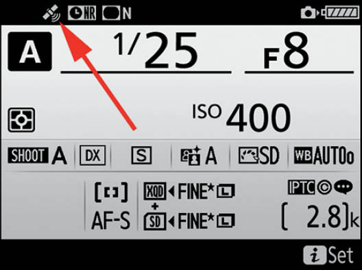
Figure 6.20I – GPS icon on the Information display screen (check for blinking or solid)
The Nikon GPS units mount either onto the camera’s Accessory shoe (figure 6.20D) or on the camera’s strap, with the included GP1-CL1 strap adapter.
Note: You can also attach some external handheld GPS units through an optional (and pricey) Nikon MC-35 cable, which uses a D-sub 9-pin connector. You must find a handheld GPS unit with a cable that will connect to the 9-pin connector on the MC-35, which is not as easy as it used to be because many handheld units use USB cable connections now.
A handheld unit I have personally used successfully is the Garmin eTrex Legend GPS unit. You can pick up a new Garmin eTrex Legend GPS unit for around US$150 on Amazon.com. It can be used with the Nikon MC-35 cable to interface with your camera, and when it’s disconnected from the camera, it can keep you from getting lost while hiking to and from that special scenic spot. To interface a handheld unit with the Nikon D500, you will need to use NMEA mode at 4800 baud. Refer to the GPS unit’s user’s manual for more information on setting the mode and baud rate. As mentioned previously, the GPS unit you choose must be compatible with the National Marine Electronics Association NMEA0183 data format version 2.01 or 3.01.
Settings Recommendation: Get the Nikon GP-1 or GP-1A GPS unit from one of many vendors, or get the Geotagger Pro 2 GPS from the Nikonians PhotoProShop (https://www.ppsna.com). Either unit is easy to use and has all the cables you need for interfacing with your camera.
If you choose one of the Nikon GPS units, the only other cable you’ll need to buy is the optional MC-DC2 shutter-release cable (coiled on the left in figure 6.20D). I use the tiny Nikon GP-1 GPS unit constantly when I’m shooting nature images so I can remember where to return in the future. After you start using a GPS unit, you’ll find it hard to stop.
If you prefer to use a smart device for GPS, you will need to learn how to configure and use the SnapBridge app, which can be more difficult and battery intensive than using an external GPS unit. For occasional GPS use, the smartphone is fine, but for intensive GPS use, I would select an external GPS unit. In my experience (so far), the external GPS unit’s physical connection uses significantly less battery power than the smart device/SnapBridge Bluetooth connection.
Wireless Remote (WR) Options
(User’s Manual: Page 307, Menu Guide: Page 144)
The Wireless remote (WR) options function lets you adjust settings for optional WR-R10 Wireless Remote Controllers. The WR-R10 plugs into the 10-pin port on the front of the camera and allows you to control multiple banks of remote (slave) flash units.
There are two settings in the Wireless remote (WR) options function:
- LED Lamp: The WR-R10 Wireless Remote Controller has two LED lamps on it that blink frequently as you use the device to control remote, radio-controlled, Speedlight flash units. In some instances, the blinking lights may be unwanted, so Nikon gives you the ability to turn them off and on as needed. The WR-R10 will work normally when the LEDs are turned off; it just won’t signal you with blinking lights.
- Link mode: Remote devices controlled by a WR-R10 Wireless Remote Controller can be paired with the controller in two different ways. The default method requires you to press the Pairing button on the WR-R10 until a Link light is illuminated on the remote device. This method is somewhat insecure since anyone with a master WR-R10 can control any slave device configured to be controlled by a WR-R10. Therefore, Nikon has provided a secondary method for pairing a master WR-R10 with its remote slave units, which requires you to type in a PIN code on each slave device.
Let’s examine how to configure each of these two settings.
LED Lamp
The LED lamps default to on, so they will blink regularly while the WR-R10 is in use. If you find this to be distracting, you can disable the LEDs. Let’s see how.
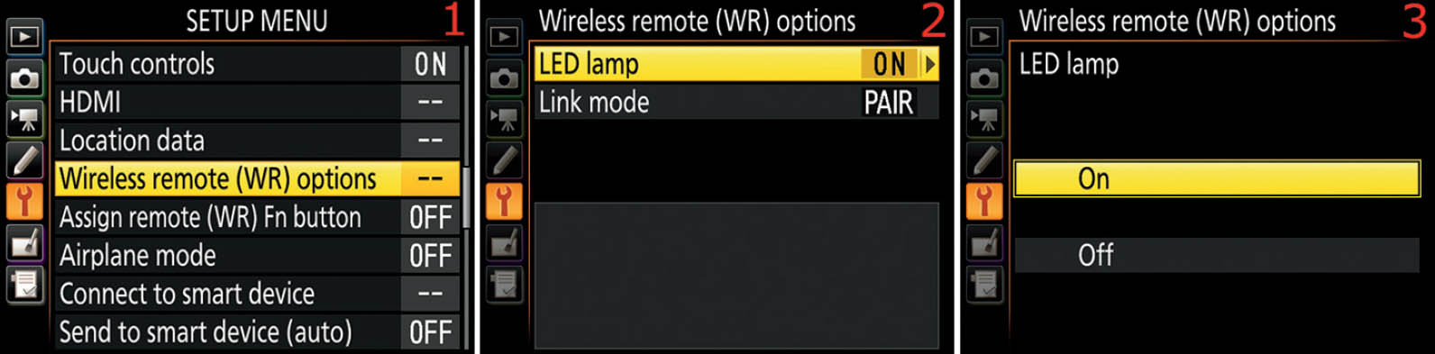
Figure 6.21A – Enable or disable the WR-R10 LED lamp
Use the following steps to enable or disable the WR-R10 LED lamps:
- 1. Follow the screen flow shown in figure 6.21A, images 1 and 2 (Wireless remote (WR) options > LED lamp), until you arrive at the third screen in the series.
- 2. Choose On or Off to control whether the LED lamps on the WR-R10 blink during use (figure 6.21A, image 3). Press the OK Button to lock in the setting.
Settings Recommendation: When I am shooting in a studio environment and creating product shots, I do not mind if the lights blink on my WR-R10 Wireless Remote Controller. In fact, I find the blinking lights reassuring.
However, during a wedding, when I have a remote flash positioned for better lighting, I do not want blinking LED lights on my WR-R10 distracting the wedding party and proceedings, so I disable them. It is easy to turn them on and off, so do so when you need to for your style of photography.
Link Mode
If you are shooting in environments where there may be other photographers using WR-R10 units and you worry about one of them trying to take control over your remote slave units, you may want to use the PIN method to pair with your slave units.
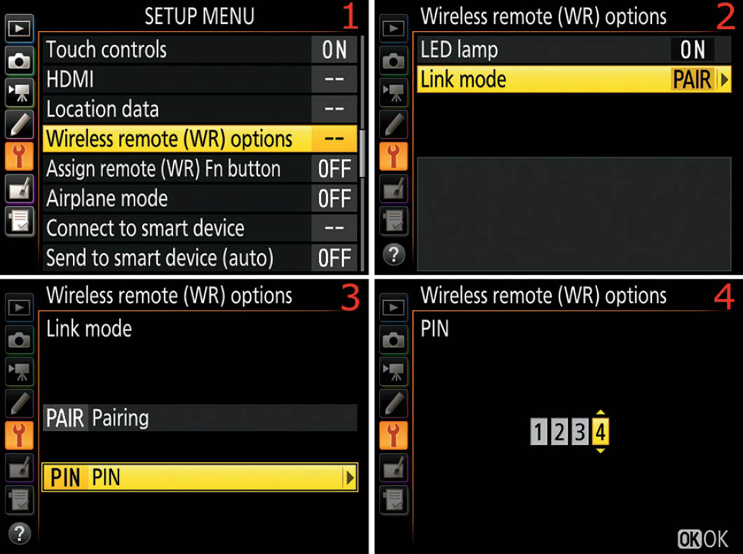
Figure 6.21B – Set the style of Link mode pairing
Use the following steps to select the style of master/remote pairing you prefer when using your WR-R10 Wireless Remote Controller:
- 1. Follow the screen flow shown in figure 6.21B, images 1 and 2 (Wireless remote (WR) options > Link mode), until you arrive at the third screen in the series.
- 2. Choose one of the following link modes:
- a. Pairing: If you choose Pairing (figure 6.21, image 3), highlight it and press the OK button to lock in the setting. You will now need to set your slave units to use Pairing and then use the Pairing button on your WR-R10 to make a link. Refer to the instructions included with the WR-R10 and the remote flash units (e.g., SB-5000) to learn how to use the Pairing button(s) and remote Link lights.
- b. PIN: If you choose PIN (figure 6.21, image 3), you will need to create a four-digit numerical pin number, from 0000 to 9999. Scroll to the right and use the Multi selector pad to scroll up or down on each number selection box until you have created your PIN (figure 6.21, image 4). Press the OK button to lock in the PIN setting. The PIN you entered will now appear on the Wireless remote (WR) options screen (figure 6.21C) so that you can access it easily in case you forget it.

Figure 6.21C – PIN code available on camera screen
Settings Recommendation: I normally use the PAIR (Pairing) setting because I work by myself most of the time. In addition to configuring the WR-R10, you will also need to configure each remote unit. Therefore, think carefully about how you will be working with your master/remote units. If you are shooting in an environment where there could be people who would like to aggravate you by taking over your remote units with their WR-R10, why not set up a PIN instead of using the Pairing button?
Assign Remote (WR) Fn Button
(User’s Manual: Page 307, Menu Guide: Page 145)
The Assign remote (WR) Fn button function allows you to program the camera to respond in various ways when you press the Fn button on an optional remote controller (one that has an Fn button, of course). You can assign 11 different Button options to the controller’s Fn button. First let’s see an alphabetical list of the settings:
- AE/AF lock
- AE lock only
- AE lock (Reset on release)
- AF lock only
- AF-ON
- [Flash] Disable/enable
- FV lock
- Live view (Same as Lv button)
- + NEF (RAW)
- None
- Preview
Because this function is so similar to many other Button option assignment functions we have already considered over the last few chapters, we will examine how to assign the Fn button but will not discuss what each Button option does.
If you do not know what a particular option does, please refer to the detailed list of functionality for each option under the Custom Setting Menu > f Controls > f1 Custom control assignment function (page 297). The Button Press Options List in that section explains each of these 11 options.
Let’s see how to assign a Button option to the Fn button on your remote controller.
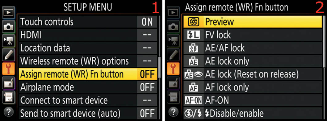
Figure 6.22 – Assigning a Button option to the remote controller’s Fn button
Use the following steps to select a Button option for an optional remote controller’s Fn button:
- 1. Choose Assign remote (WR) Fn button from the Setup Menu and scroll to the right (figure 6.22, image 1).
- 2. Referring to the Button Press Options List on page 297, select one of the 11 available Button options (figure 6.22, image 2) and then press the OK button to make the Fn button assignment.
Airplane Mode
(User’s Manual: Page 307, Menu Guide: Page 145)
Airplane mode in the D500 works in a similar way to the airplane mode in your smart device. When you enable Airplane mode, the camera will turn off all radio transmissions of any type from within the camera body, including Wi-Fi, Bluetooth, and Eye-Fi cards.
However, if you have a WR-R10 or another wireless controller plugged into the 10-pin port, it will continue sending and receiving radio signals. Unplug any wireless controllers to have true radio silence.

Figure 6.23 – Enabling or disabling Airplane mode (no radio signals)
Use these steps to enable or disable Airplane mode in the Nikon D500:
- 1. Choose Airplane mode from the Setup Menu and scroll to the right (figure 6.23, image 1).
- 2. Choose Enable to turn on Airplane mode and cause the camera to go into radio-silent mode, or Disable to turn Airplane mode off and allow the camera to send and receive radio signals (figure 6.23, image 2). Press the OK button to lock in the setting.
Settings Recommendation: When I go out into the wild to shoot my nature images, I often set the camera to Airplane mode. In fact, I keep it as one of the options under My Menu (page 488) so that I can access it quickly. Sometimes, I need all the battery power I can get, and Airplane mode conserves battery.
Connect to Smart Device
(User’s Manual: Page 307, Menu Guide: Page 146)
The Connect to smart device function is the core function to enable Bluetooth and Wi-Fi connectivity with your Nikon SnapBridge app. This connection explanation is based on interfacing a Nikon D500 with a Google Nexus 7 (2013) model tablet with NFC (near field communication) capability, running the Android Marshmallow 6.0.1 operating system. The SnapBridge app is available for both Adroid and iOS as of September 2016.
The most effective way to connect your D500 to the SnapBridge app on an Android smartphone or tablet is to use the NFC system built into most newer smart devices. Although some older devices will work—I also connected the D500 with a several-year-old Samsung Galaxy S3—it is best to stay with newer devices. You can try to connect with older smart devices, but you may or may not be successful. It surely won’t hurt to try.
Let’s discuss how to connect your D500 to an Android SnapBridge app.
Enabling Services You Will Need for Pairing
To make and use the connection (pairing) between your camera and smart device, you will need to use multiple radio-based services, including NFC, Bluetooth, and Wi-Fi. Therefore, before you attempt to make the connection, please enable NFC, Bluetooth, and Wi-Fi on your smart device, and if you want to use GPS location info (page 405), enable Location services.
Additionally, you will need to set up Wi-Fi on the D500 before you attempt to make the SnapBridge connection, unless you are satisfied with the current SSID (service set identifier), authentication and encryption type, and default password (NIKOND500). Once the D500/Smart device connection is made, Wi-Fi changes are locked out. If you have not yet configured Wi-Fi, please go to the Wi-Fi section in this chapter (page 425), set up each part of the Wi-Fi system, and then return here.
Please note that Bluetooth is disabled on the Nikon D500 until you make a connection (pair) to the SnapBridge app (or plug in a Nikon WT-7A wireless transmitter for advanced Bluetooth operation). What I mean is, you will not be able to access the Bluetooth function on your camera’s Setup Menu—as described later in this chapter under the Bluetooth section (page 432)—until you have fully paired the D500 to your smart device. Until then, the Bluetooth function will be grayed out and unavailable.
Here are the steps you should take before attempting to pair the Nikon D500 to an Android smart device:
- 1. Enable NFC, Bluetooth, Wi-Fi, and Location services on your smart device.
- 2. Install the SnapBridge app on your smart device, but do not open it yet.
- 3. Configure Wi-Fi on your D500 under the Setup Menu > Wi-Fi function (page 425). Create a new SSID name if you do not like the default name, choose an Authentication/encryption type, and add a more secure Password.
- 4. Follow the pairing instructions in the next subsection, Pairing the D500 with Your Smart Device. Be persistent in your pairing efforts; it may work immediately or it may take you several tries to finally get it to work. The first time I did it, the connection was immediate. When I blew that connection away to try a different device and get some new screen shots, it took me over an hour to make a second connection. If you are having problems, why not discuss your efforts in the D500 forum on Nikonians.org? Don’t give up; once you make the pairing, it seems to be pretty stable and works well.
Now let’s spend some time working through how to make a connection between your D500 and a smart device.
Pairing the D500 with Your Smart Device
The process of pairing the two devices can be easy, but it usually takes a bit of fiddling around (as we say in Tennessee). Let’s go through the basic screens and steps used to make a connection between your D500 and a smart device (SnapBridge app).
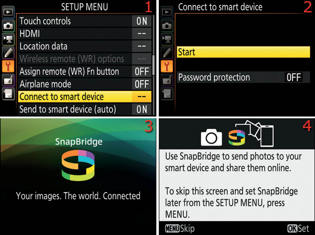
Figure 6.24A – Pairing the D500 and smart device, initial steps
Use these initial steps to start the Pairing process:
- 1. Choose Connect to smart device from the Setup Menu and scroll to the right (figure 6.24A, image 1).
- 2. Select Start from the Connect to smart device menu and scroll to the right (figure 6.24A, image 2).
- 3. Nikon’s SnapBridge welcome screen will show on the Monitor briefly (figure 6.24A, image 3), and then the camera will switch to the next screen.
- 4. The final screen in the initial series is shown in figure 6.24A, image 4. At this point in the process, your smart device must be ready to pair (NFC, Bluetooth, Wi-Fi, and Location services enabled). Press the OK button to start the process. Next we will consider the NFC connection screens.

Figure 6.24B – Nikon D500 NFC connection screens
- 5. The next screen in the series is the NFC connection screen on the D500 (figure 6.24B, image 1). Open the SnapBridge app on your smart device and touch the back of your smart device to the N-Mark (NFC symbol) on the Memory card slot cover (door) of the D500. The N-Mark on the D500 looks like the symbol at the tip of the red arrow in image 1, and it is just behind the D500’s hand grip on the memory card door. This is the NFC antenna (N-Mark) for the D500 and must be within an inch of your smart device until you hear a ding sound.
- 6. Once you have heard the ding, the popup message shown in figure 6.24B, image 2, will appear on the D500. It says Check the display on the smart device. As soon this screen appears, quickly look at the SnapBridge app on your smart device and follow the next step. You have only a few seconds before the pairing effort will fail so move quickly.

Figure 6.24C – Smart device NFC connection screens (top half of screens is shown)
- 7. The SnapBridge app should now be displaying the Connect to Camera screen (figure 6.24C, image 1). Within about a second, the name you chose for the Wi-Fi SSID setting will appear just under Camera name. Touch the SSID name (e.g., D500-3003931) with your finger to select it. A message saying Connecting to camera . . . will appear for a few seconds, and then the SnapBridge screen shown in figure 6.24C, image 2, will appear. Do not touch the Pair touch button shown on the SnapBridge screen yet. You must press the OK button on the camera first!

Figure 6.24D – Authentication code (Auth. Code) screen on D500
- 8. When the Auth. code screen appears on the D500 (figure 6.24D, image 1), press the camera’s OK button quickly. Then press the Pair touch button on the smart device’s SnapBridge app screen (figure 6.24C, image 2). You have only a few seconds between each of these operations before the camera will give up and display a message that says Unable to connect. So you must act very quickly. When you have a successful connection, the D500 will display the screen shown in figure 6.24D, image 2, and your two devices are paired. The SnapBridge app will display a series of five screens explaining how to use the app.
Congratulations, if you succeeded! If the pairing failed, try again by starting over at step 4. Above all, don’t give up. Keep trying and you will be successful!
Using a Password for the Bluetooth Connection
Since we live in a world where people love to hack others’ devices, you may want to use a password for the Connect to smart device function, for the camera’s Bluetooth radio signal only. The D500’s Wi-Fi system (page 425) has a separate password. Here is how to set up a Bluetooth password.
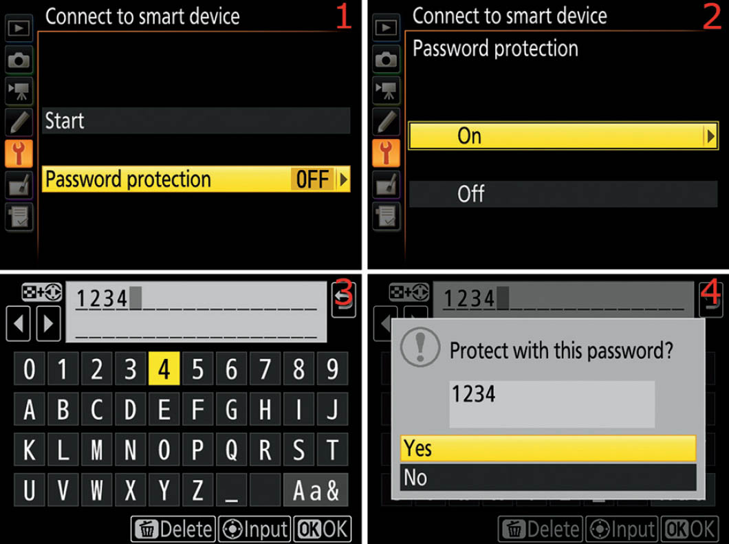
Figure 6.24E – Setting up a password for the Connect to smart device function
Use the following steps to set up a password for the Connect to smart device function. This does not make you type in a password to use SnapBridge. The password applies for modifications to the pairing configuration under the Connect to smart device function only:
- 1. Choose Password protection from the Connect to smart device function found on the Setup Menu (figure 6.24E, image 1) and scroll to the right.
- 2. Choose On from the Password protection menu (or Off to disable) and then scroll to the right (figure 6.24E, image 2).
- 3. Type in your password choices with the password touch screen (figure 6.24E, image 3). You can choose upper- and lowercase letters, numbers, and symbols by touching the Aa& touch button. When you have typed in your password, touch the OK touch button in the lower-right corner.
- 4. A popup screen will appear with the question: Protect with this password? Yes/No. Choose Yes to set the password or No to cancel. If you chose Yes, your password is set and from now on (until disabled) when anyone tries to enter the Connect to smart device function, the password request screen will appear (figure 6.24F, image 2).
Password Entry for the Bluetooth Connection
Once you have created a password for the Connect to smart device function, as discussed in the previous subsection, you must use these steps to unlock the function to modify the pairing setup.

Figure 6.24F – Entering a password for Connect to smart device
Use these steps to enter the password-protected Connect to smart device function:
- 1. Select Connect to smart device from the Setup Menu (figure 6.24F, image 1) and scroll to the right.
- 2. The password screen will now appear. Use your finger to select the characters in the password you set in the previous subsection. Use the Aa& touch button to change among upper- and lowercase letters and symbols. Once you have typed in the password, touch the OK touch button.
- 3. You will now be presented with the normal Start screen, which allows you to modify the configuration of the SnapBridge/D500 pairing.
Bluetooth versus Wi-Fi
The Bluetooth connection (page 432) allows your smart device to communicate directly with your Nikon D500 using low-energy Bluetooth (BLE). Your Nikon D500 and your smart device set up their own private Bluetooth network. Your smart device must be compatible with Bluetooth 4.0 and have BLE capability (most devices up to three or four years old work with BLE).
The Wi-Fi connection (page 425) sets up an “ad hoc” wireless network between the Nikon D500 and the SnapBridge app on your smart device. The connection does not depend on any other Wi-Fi networks that may or may not be available in the area. It is a standalone, private connection between your camera and smart device.
The Nikon D500 does not work with Nikon’s older WMU app. The camera is designed to connect only with smart devices running the SnapBridge app.
Additional Connectivity Settings of Interest
There are some related settings in the Setup Menu that you should take note of at this point. Each one affects how the camera uses its smart device connection:
- Setup Menu > Time zone and date > Sync with smart device [page 359]
- Setup Menu > Location data > Download from smart device [page 405]
- Setup Menu > Send to smart device (auto) [page 422]
- Setup Menu > Bluetooth > Send while off [page 434]
Now that you have a better understanding of the Connect to smart device process, check these related settings and make sure they are configured to meet your needs.
Send to Smart Device (Auto)
(User’s Manual: Page 308, Menu Guide: Page 147)
If you want to send all your pictures to your smart device for a particular shooting session, you can do so with the Send to smart device (auto) function. The SnapBridge app and camera have a relationship defined by the Connect to smart device function we considered in the previous section (page 416).
You must enable the Send to smart device (auto) function on your D500 (figure 6.25A) and the Auto download setting on the SnapBridge app (figure 6.25B), and select the size of the images for download (2 MP or original size). Keep your smart device within a few feet of the D500 for automatic transfer.
Enabling Send to Smart Device (Auto)
First let’s examine how to enable or disable the Send to smart device (auto) function on the Nikon D500. With this function enabled (On), the camera will seek the SnapBridge app on your smart device as it takes pictures. If it finds the app, and if the app’s Auto download setting has been enabled to receive images, the camera will immediately transfer the images to your smart device in the size you selected (2 MP or original size).
If the SnapBridge app is not available, or if its Auto download feature is set to Off, the camera will automatically mark—for later download—up to 1,000 images at a time as you take them. As soon as the SnapBridge app becomes available, the camera will attempt to transfer the marked images using low-energy Bluetooth (BLE) as its first choice of protocols.

Figure 6.25A – Enabling or disabling the Send to smart device (auto) function
Use the following steps to enable or disable the Send to smart device (auto) function:
- 1. Select Send to smart device (auto) from the Setup Menu and scroll to the right (figure 6.25A, image 1).
- 2. Highlight On or Off to enable or disable automatic image transfer to the SnapBridge app on your smart device (figure 6.25A, image 2). Press the OK button to lock in the setting.
Enabling Auto Download on the SnapBridge App
The Auto download setting in the SnapBridge app is available for those times when you want to transfer all of the images you are currently taking to your smart device. Let’s examine the screens in SnapBridge that you must configure for the setting to work.

Figure 6.25B – Enabling Auto download on the SnapBridge app
Use the following steps to enable Auto download on the SnapBridge app:
- 1. Open the SnapBridge app and navigate to the Connect screen by touching the Connect symbol (figure 6.25B, image 1, top red arrow). Notice that on the Connect screen in image 1, just above where it says D500, there are several icons. The icon on the left represents your smart device and the one on the right represents your D500 (with its battery charge level). In the middle there is a Bluetooth symbol in a circle. If the Bluetooth symbol is not present, the camera and smart device are not yet communicating. The symbol should appear after you complete the first four steps in this series.
- 2. Touch Auto download to open the Auto download configuration screen (figure 6.25B, image 1, bottom red arrow).
- 3. The Auto download screen shown in figure 6.25B, image 2, has two settings you must configure. First, move the Auto download slider to the right to turn Auto download on (figure 6.25B, image 2, top red arrow).
- 4. Next, select an image size for the images you want to send to the smart device: 2 megapixels or Original size. My SnapBridge app is set to 2 megapixels (figure 6.25B, image 2, bottom red arrow). Original size JPEG images can take up a lot of space on your smart device. Most of us will select 2 megapixels to save space; this size will allow for a good Internet-quality image or small print (e.g., 4×6 inch or 10×15 cm).
- 5. Now go take some pictures. Make sure you keep your smart device nearby with the SnapBridge app open so that it can communicate with the camera. When you look at the SnapBridge app after you have taken some pictures, you will see what is described in the following steps (figure 6.25C).

Figure 6.25C – Transferring images via Auto download
- 6. As the pictures you just took are flowing into the SnapBridge app, you will see two new symbols above the camera and smart device icons on the SnapBridge screen (figure 6.25C, image 1, red arrows). The symbol at the tip of the top red arrow (mountain peaks) is a moving symbol that represents the pictures that are downloading. You will see it moving from the camera symbol to the smart device symbol repeatedly as the images are downloading from the camera into the app. The symbol at the tip of the bottom-right red arrow in image 1 tells you that multiple images are being transferred.
- 7. To examine the pictures already downloaded and see more as they flow into the app, touch the Gallery symbol (figure 6.25C, image 2, top red arrow). This opens the Snap-Bridge Gallery, which shows you the images that are on the smart device, sorted according to when they were taken (number of hours ago) and image size. In figure 6.25C, image 2, you can see that the top green leaf image is labeled with D500/Original size (middle red arrow), and the three images at the bottom of the screen are labeled with D500/2 megapixels (bottom red arrow).
- 8. If you touch one of the images in the Gallery (figure 6.25C, image 2), the picture will open up to full screen and you will see the following information: the date and time the image was taken, the file name, megapixel size, file size, camera (Nikon D500), lens, f-stop, and shutter speed.
Settings Recommendation: I generally leave the Send to smart device (auto) function set to Off because I want to choose when and where I transfer files, not leave it up to the camera. Plus, I like to be selective about which image files to transfer to the limited memory of my smart device. However, if you are in a hurry, this is an easy way to get images from your camera to your smart device quickly.
Online Web Instructions for SnapBridge
Nikon has provided an online resource for using the SnapBridge app. Open the SnapBridge online help website at this web address:
http://nikonimglib.com/snbr/onlinehelp/en/index.html
Wi-Fi
(User’s Manual: Pages 308 and 354, Menu Guide: Page 147)
The Wi-Fi function within your D500 is an auxiliary communications protocol for those times when a more robust radio signal with greater range is needed. For instance, the SnapBridge app provides a means to remotely control your camera (Remote photography) so that you can do something such as set up your camera on a tripod out by the birdfeeder and control the D500 from behind a window in your house. Or you may want to transfer a video you have created in the camera to your smart device. You cannot use Bluetooth to do either of these two actions.
You can also have the SnapBridge app display thumbnails of every photo on the entire camera, selected by XQD card slot or SD card slot and from the individual folders within. Then you can choose individual pictures for immediate transfer to the SnapBridge app. Evidently, using Wi-Fi is more efficient when examining all available pictures on the camera because the SnapBridge app is updating so many thumbnails as you scroll through the images.
You can enable Wi-Fi only under the circumstances I just discussed: Remote photography, video transfer, and the downloading of selected pictures from within the SnapBridge app.
First, let’s examine the SnapBridge app for instructions on how to enable the Wi-Fi system.
Using Wi-Fi in the SnapBridge App

Figure 6.26A – Enabling Wi-Fi on the SnapBridge app
To learn how to use the SnapBridge app for Wi-Fi, we will use the screen shown in figure 6.26A, images 1 and 2. Notice that there are red arrows pointing to various items and that each arrow has a letter assigned to it. We will refer to the letters (e.g., A, B, C) when discussing items on the screen. Here are the steps to understand and enable Wi-Fi:
- 1. To get started, open your SnapBridge app and touch the Camera symbol (A). This will open the Camera screen (figure 6.26A, image 1), giving you access to Wi-Fi for the three specific actions we discussed in the previous paragraphs. Image 1 shows the Snap-Bridge app Camera screen with Bluetooth only enabled (B), whereas image 2 shows the same screen with Wi-Fi enabled (E). Notice the differences in the symbols; one (B) is for Bluetooth and the other (E) is for Wi-Fi. You will rarely see the Wi-Fi symbol (E) because the SnapBridge app immediately executes the function you select that enables Wi-Fi (C and D), and switches away from the Camera screen seen in images 1 and 2. When you exit one of the actions (e.g., Remote photography), the camera immediately switches Wi-Fi off and the Wi-Fi symbol (E) is replaced with the Bluetooth symbol (B).
- 2. To choose Wi-Fi-based Remote photography, touch the Remote photography (C) Snap-Bridge menu item. The SnapBridge app will pop up a small window with the following question: Wi-Fi is required for remote photography. Wi-Fi will now connect to the selected camera. OK? Touch OK on the popup window and the camera will enable Wi-Fi and switch to Remote photography mode, giving you control of the camera from the Snap-Bridge app.
- 3. To enable Wi-Fi-based downloading of selected pictures (or movies), touch the Download selected pictures (D) SnapBridge menu item. The SnapBridge app will pop up a small window that says Switch from Bluetooth to Wi-Fi for connection to D500? Switch to a Wi-Fi connection to view and download movies from the camera. Touch OK on the popup window and the camera will enable Wi-Fi and switch to Download selected pictures mode, allowing you to use the SnapBridge app to move between the camera’s two memory card slots, and among the folders on each memory card, to select specific images for immediate download to your smart device.
Now let’s consider how to set up Wi-Fi on the camera, including the SSID (identifying name), security methods, and Wi-Fi password.
Configuring Wi-Fi on the Nikon D500
The Wi-Fi setting on the Nikon D500’s Setup Menu allows you to configure the necessary connection information for devices like the Nikon WT-7A wireless transmitter and even for the SnapBridge app.
If you have an active partnership (Paired devices) in place between the camera and a smart device, you cannot do anything with the Wi-Fi menu on the D500 except view the Current settings. To change Wi-Fi settings, such as the SSID or password, you must delete any active SnapBridge pairing setups by using the Setup Menu > Bluetooth > Paired devices setting (page 433). You can pair the smart device again after configuring Wi-Fi, or you can leave Wi-Fi at the current default settings.
Note: The D500 is designed to work with the Nikon WT-7A wireless transmitter, which screws onto the bottom of the camera like a battery pack, allowing the camera to communicate with your computer (or other devices) on an ad hoc wireless (Wi-Fi) network.
You can use the camera’s Wi-Fi capability in a limited way without a WT-7A transmitter to do things like upload videos from the camera to the SnapBridge app (figure 6.26A).

Figure 6.26B – Configuring the Wi-Fi system on the D500 camera
Use the following steps to configure the Wi-Fi system on your D500:
- 1. Follow the screen flow shown in figure 6.26B, images 1 and 2 (Wi-Fi > Network settings), until you arrive at the third screen in the series.
- 2. Figure 6.26B, image 3, reveals the Network settings screen. We will consider each of the items on the Network settings menu (figures 6.26C through 6.26F).
SSID
Technically speaking, the SSID (Service Set IDentifier) is a unique, case-sensitive, alphanumeric (32-character maximum) identifier that is attached to the header of IP packets transmitted over a wireless local area network (WLAN). The SSID identifies the network that is transmitting the named IP packets so that when the transmitted data packets are reassembled, they can be clearly identified as belonging to a known wireless network.
Here’s a translation of the last paragraph: The SSID is the unique name of a Wi-Fi network that identifies the data the network sends among its participants as coming from a known, valid device participating on that network (e.g., D500, smart device, computer).
Your D500 will communicate on a Wi-Fi network using a known SSID, which you can provide (e.g., My-Cool-Nikon-D500), or you can let the camera provide it automatically (e.g., D500-3003931, where the seven digits after D500- are the camera’s serial number).
Let’s examine how to choose an SSID for your camera to use when communicating with your smart device.

Figure 6.26C – Choosing an SSID for the Wi-Fi network (continues from figure 6.26B)
Use the following steps to choose an SSID for Wi-Fi communication:
- 1. Figure 6.26C continues where figure 6.26B leaves off. Choose SSID from the Network settings menu and scroll to the right.
- 2. Either use the current SSID, which will be similar to D500-3003931, or create your own SSID with the easy-to-use touch controls shown in figure 6.26C, image 2. Remember that the SSID is case sensitive, so MyD500 is not the same as myd500. Press the OK touch button (or press the physical OK button) when you are satisfied with the SSID.
Settings Recommendation: I leave my camera’s SSID set to the default value because it identifies the camera type and serial number very effectively. You may wish to use some other clever SSID. However, just remember that an SSID is limited to 32 characters and is case sensitive.
Authentication/Encryption
The Nikon D500 can carefully protect your personal information and images as they flow across a Wi-Fi network by using WPA2-PSK (Wi-Fi Protected Access 2 – Pre-Shared Key) authentication, with AES (Advanced Encryption Standard) encryption. Or you can choose to turn off authentication and encryption and transmit your images without protection. The camera defaults to having authentication and encryption enabled.

Figure 6.26D – Authentication/encryption for the Wi-Fi network (continues from figure 6.26B)
Use the following steps to enable or disable the camera’s Wi-Fi security:
- 1. Figure 6.26D continues where figure 6.26B leaves off. Choose Authentication/encryption from the Network settings menu and scroll to the right.
- 2. Select WPA2-PSK-AES to use Authentication/encryption, or choose OPEN to disable Authentication/encryption (figure 6.26D, image 2). Press the OK button to lock in your choice.
Password
Due to the need for security in any Wi-Fi system these days, Nikon has wisely provided a means to password-protect the connection to the camera’s Wi-Fi. The default password is NIKOND500, which, of course, is not very secure. Therefore, if you are going to use the Wi-Fi system in a place where there might be other photographers, you may want to change the password to something much harder to guess.

Figure 6.26E – Changing the Wi-Fi system password (continues from figure 6.26B)
Use the following steps to change the password to a more secure one:
- 1. Figure 6.26E continues where figure 6.26B leaves off. Choose Password from the Network settings menu and scroll to the right.
- 2. Use the touch-screen controls to replace the current Wi-Fi password (NIKOND500) with a more secure password (figure 6.26E, image 2). Touch the OK touch button or press the physical OK button to save the new password.
Channel
Wi-Fi systems allow you to use a selected channel to prevent interference with nearby Wi-Fi networks. On the D500 you can choose from channels 1 to 11, or you can just select Auto and let the camera decide. Let’s see how to choose one of the settings.

Figure 6.26F – Selecting a Wi-Fi channel (continues from figure 6.26B)
Use the following steps to choose a channel for your camera’s Wi-Fi system:
- 1. Figure 6.26F continues where figure 6.26B leaves off. Choose Channel from the Network settings menu and scroll to the right.
- 2. You have a choice of Auto or Manual (figure 6.26F, image 2). If you want the camera to decide which Channel to use, highlight Auto, press the OK button, and skip step 3. Otherwise, select Manual and scroll to the right (figure 6.26F, image 3).
- 3. Use the Multi selector pad to scroll up or down and choose a channel from 1 to 11. Press the OK button to lock in the setting.
Current Settings
Current settings lets you easily examine the camera’s currently configured Wi-Fi settings. Once you make a Bluetooth connection to your smart device (pair), Current settings is the only menu item that will be available for use. The rest of the Wi-Fi menu will be grayed out and unavailable. There is nothing to adjust within this setting. It is for informational use only.

Figure 6.26G – Viewing the current settings for the Wi-Fi system
Use the following steps to view the current Wi-Fi settings:
- 1. Follow the screen flow shown in figure 6.26G, images 1 and 2 (Wi-Fi > Current settings), until you arrive at the third screen in the series.
- 2. Figure 6.26G, image 3, shows the Current settings screen where you will find information on the current configuration of the Wi-Fi system. Press the OK button when you are finished viewing the current settings.
Reset Connection Settings
If you want to do a complete reset of the Wi-Fi system and change all settings back to their factory defaults, you can do so with the Reset connection settings option.

Figure 6.26H – Resetting the Wi-Fi system back to factory default settings
Use the following steps to reset the Wi-Fi system back to factory default settings:
- 1. Follow the screen flow shown in figure 6.26H, images 1 and 2 (Wi-Fi > Reset connection settings), until you arrive at the third screen in the series.
- 2. Select Yes from the popup screen that asks Reset Wi-Fi settings? and press the OK button to reset Wi-Fi back to factory default settings. Select No to cancel.
Note: In order to use the Wi-Fi system for things like Remote photography, you must already have an active Bluetooth connection between the camera and a smart device. I tried disabling Bluetooth and then using Wi-Fi as discussed in the steps associated with figure 6.26A, but I was never able to make a Wi-Fi connection. Apparently, the camera and SnapBridge app depend on Bluetooth for basic communication and allow a Wi-Fi connection only when Bluetooth is activated first.
Bluetooth
(User’s Manual: Page 308, Menu Guide: Page 148)
The Bluetooth function allows you to control the primary communications channel between the camera and the SnapBridge app on your smart device. To properly communicate with your camera, your smart device should be running Bluetooth version 4.0 or later, and should have Bluetooth Smart Ready/Low Energy (BLE) capability. BLE tends to save battery; however, using Bluetooth services still tends to run the battery down more quickly, so its a good idea to have multiple batteries available.
Until you pair a smart device running the SnapBridge app with your D500, the Bluetooth menu item will be grayed out and unavailable in the camera’s Setup Menu. You cannot enable Bluetooth manually in any other way. As soon as the camera is paired with a smart device, the Bluetooth menu will become available for selection and configuration.
Let’s examine each item on the Bluetooth menu.
Network Connection

Figure 6.27A – Enabling or disabling Bluetooth
Use the following steps to enable or disable the camera Bluetooth service:
- 1. Follow the screen flow shown in figure 6.27A, images 1 and 2 (Bluetooth > Network connection), until you arrive at the third screen in the series.
- 2. Highlight Enable or Disable and press the OK button to lock in the setting (figure 6.27A, image 2).
Settings Recommendation: If you disable the Network connection setting, the camera will not be able to communicate with the SnapBridge app on your smart device. From my experience, the Bluetooth connection must be active to use the SnapBridge Wi-Fi connection for Remote photography or to transfer movies.
It is best to leave Bluetooth enabled when you are going to be using the SnapBridge app now or in the near future. However, if you will not be using the SnapBridge app for a while, disable the Bluetooth connection to save battery life.
Paired Devices
The D500 is capable of establishing a relationship with more than one smart device. For example, you might want to pair your camera with both your smartphone and tablet. You can’t use the smart devices at the same time, but you can easily and quickly switch between devices when a larger or smaller screen is needed.
My D500 is currently connected to my Google Nexus 7 tablet (2013 version) and my Samsung Galaxy S3 smartphone. Both devices are several years old, but they work quite well with SnapBridge.
To pair more than one smart device with your camera, follow the steps found in the Connect to Smart Device section earlier in this chapter (page 416). Once you have connected multiple smart devices, they will become available under the Paired devices setting (figure 6.27B).
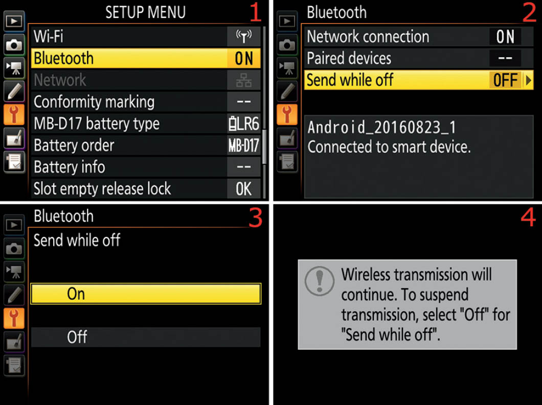
Figure 6.27B – Choosing a Paired device
Use the following steps to choose one of the smart devices you have previously paired with the Connect to smart device function (page 416):
- 1. Follow the screen flow shown in figure 6.27B, images 1 and 2 (Bluetooth > Paired devices), until you arrive at the third screen in the series.
- 2. Scroll up or down with the Multi selector pad and highlight one of the devices listed, and then press the OK button to use the listed device (figure 6.27B, image 3). If you have paired only a single device, only that device will show up in the Paired devices list. You can delete a Paired device by highlighting it and pressing the Delete button.
Note: For whatever reason, my D500 chose to assign exactly the same Paired devices identifier to both of my Android devices. This is a little confusing, but it works fine. When I select one of the two devices, I make sure the SnapBridge app on the device I want to use shows the Bluetooth symbol in the circle between the smart device and camera icons (figure 6.25C, image 1). If it never shows up, I select the other device in the Paired devices list (figure 6.27B, image 3).
Send While Off
This setting is designed to allow transfer of images from your camera to your smart device even when the camera is turned off. If you have the Send to smart device (auto) function (page 422) set to On, the camera will attempt to connect to your smart device and transfer the pictures you are currently taking to that device. If the D500 cannot communicate with the smart device, the camera will mark each image you take (up to 1000 pictures) for later transfer, which will occur as soon as the camera reestablishes communication.
Let’s say you’ve been out shooting and you forgot to take your smart device with you, and now you have a couple hundred images marked for upload. If you have Send while off enabled, you can open the SnapBridge app, wait for the Bluetooth symbol to appear, see that the images have started transferring, and then turn off the camera. The transfer will continue in the background, and the Bluetooth connection will be maintained until the transfer is complete. Then Bluetooth will disconnect.

Figure 6.27C – Enabling Send while off
Use the following steps to enable or disable the Send while off setting:
- 1. Follow the screen flow shown in figure 6.27C, images 1 and 2 (Bluetooth > Send while off), until you arrive at the third screen in the series.
- 2. Select On to enable the setting or Off to disable it (figure 6.27C, image 3). Press the OK button to lock in the setting.
- 3. When Send while off is enabled, the screen shown in figure 6.27C, image 4, will appear on the camera’s Monitor when you turn the camera off during image transfer. It is a reminder that you have left this setting active.
Note: If you want to force the camera and smart device to stay connected via Bluetooth, simply set Custom Setting Menu > c Timers/AE lock > c2 Standby timer (page 263) to a long setting, such as 10 min, 30 min, or No limit (the default is 6 sec). This will allow the camera to maintain a constant Bluetooth connection. While the Standby timer is active, the camera does not shut off the light meter and it is ready to take pictures at all times, leaving all radio-based connections active.
The camera and the SnapBridge app seem to keep the Bluetooth connection active as long as necessary whenever an actual image transfer is occurring, so normally you would not have to enable the Send while off setting for standard use. The Send while off setting overrides the Standby timer, meaning the Standby timer’s shutdown (timeout) will not prevent images from being transferred.
Settings Recommendation: I generally leave Send while off disabled. I do not see any evidence in the SnapBridge app that the camera maintains the Bluetooth connection when this function is active, except when it is actually transferring images or when the light meter is active. However, I am always looking for ways to save battery power, so I disable any functions that could potentially drain the battery unless I truly need the service.
If you do a lot of image transfer, or have a large number of images marked for transfer, you may want to enable this setting, at least long enough to complete the large transfer.
Network
(User’s Manual: Page 308, Menu Guide: Pages 148, 189, 198)
Network allows you to interface the Nikon D500 with a wireless or wired Ethernet network. You must be using a Nikon WT-7 wireless transmitter and the camera must be tethered to it with the supplied USB cable. The following five modes are available while the D500 and WT-7 are connected:
- FTP upload: Transfer your images to an FTP server, or upload new images as they are taken.
- Image transfer: Transfer your images to a computer, or upload new images as they are taken.
- Camera control: Use the optional Camera Control Pro 2 software to save new images and videos directly to your computer.
- HTTP server: View and take pictures remotely, using a computer web browser or iPhone.
- Synchronized release (wireless only): Let the Nikon D500 be a master camera that causes the shutters to release on multiple remote (slave) cameras when the D500 releases its shutter.
Professional studio and sports shooters may be using the WT-7 on an Ethernet network. The majority of Nikon shooters will transfer images via USB cable or by using SnapBridge on their smart devices.
Using this WT-7 wireless transmitter unit is beyond the scope of this book. Please refer to the Nikon WT-7 User’s Manual for more information.
Eye-Fi Upload
(User’s Manual: Page 308, Menu Guide: Page 149)
The Eye-Fi upload function allows you to use an Eye-Fi card to send images from your camera to your smartphone, tablet, Windows PC, or Mac, through a “Direct Mode” (ad hoc) Wi-Fi connection or by using your local external Wi-FI network. The Eye-Fi card does not use the Nikon D500’s built-in Wi-Fi system. Instead it provides its own separate Wi-Fi capability.
The Eye-Fi upload function appears on the Setup Menu of your D500 only when you have an Eye-Fi card inserted in the camera. Otherwise, the camera does not even show the Eye-Fi Upload menu selection between Network and Conformity marking on the Shooting Menu.
The Eye-Fi company makes several SD cards with built-in Wi-Fi transmitters. Figure 6.28A shows two of my Eye-Fi cards: the Pro X2 8GB high-speed Class 6 SDHC card and the mobi 8GB Class 10 SDHC card.
With an Eye-Fi card inserted in your camera and the Eye-Fi app installed on your smart device or computer, you can take pictures that are automatically transferred to the Eye-Fi app. Eye-Fi’s mobi and mobiPRO cards will do ad hoc transfers, meaning that they don’t need an in-home or external Wi-Fi network connection, but will send pictures directly (Direct mode) to a paired smart device or computer. In effect, the Eye-Fi card becomes a wireless (Wi-Fi) transmitter that can talk directly to a Wi-Fi-enabled smart device or computer, with or without a local external network. You can acquire the Eye-Fi app as a free download from your smart device’s app store.

Figure 6.28A – Eye-Fi cards
Note: Eye-Fi is deprecating the Pro X2 cards as this book is being written. Update your Eye-Fi app and get more information on the Pro X2 deprecation at the www.eye.fi website. They have recently replaced both the mobi and Pro X2 cards with a new card called the mobiPro, combining the functionality of the formerly confusing Eye-Fi product line into one powerful card. Visit the Eye-Fi website for more information.
Enabling Eye-Fi Uploads on the D500
An Eye-Fi card does not use any more battery life than a normal SD card until you enable Wi-Fi. Unless you are currently shooting images for immediate transfer, I wouldn’t leave the Eye-Fi upload feature (Wi-Fi) enabled. Why waste battery life?
Note: You must disable Airplane mode (Setup Menu > Airplane mode) and Bluetooth (Setup Menu > Bluetooth > Network connection) in order to use the Eye-Fi card.
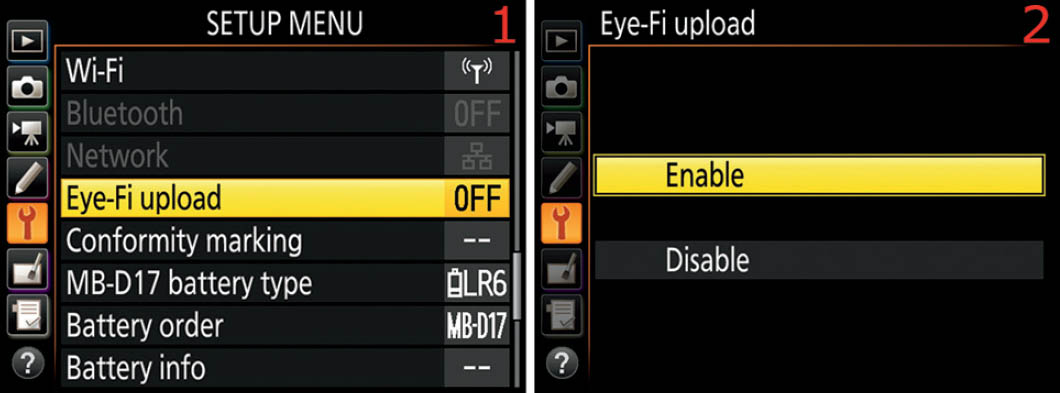
Figure 6.28B – Enabling Eye-Fi (Wi-Fi)
Here are the steps to enable or disable Eye-Fi upload to the Eye-Fi Mobile app:
- 1. Choose Eye-Fi upload from the Setup Menu and scroll to the right (figure 6.28B, image 1).
- 2. Select Enable or Disable from the Eye-Fi upload screen (figure 6.28B, image 2). Press the OK button to lock in the setting.
An Eye-Fi card doesn’t give you the large wireless range and multiple modes that the powerful Nikon WT-7A transmitter offers, but it allows you to shoot an event within 50 to 90 feet of a smart device or computer and have immediate wireless file transfer capability.
Note: On pages 149–150 of the Nikon D500 User’s Manual, you will find a discussion of various Eye-Fi card status symbols. If you are a frequent user of Eye-Fi card technology, you may want to learn what the symbols mean.
Conformity Marking
(User’s Manual: Page 309, Menu Guide: Page 150)
Conformity marking is a simple function that lets you see the symbols for the various industry standards with which your camera conforms. These standards have symbols that you can research if you so desire.
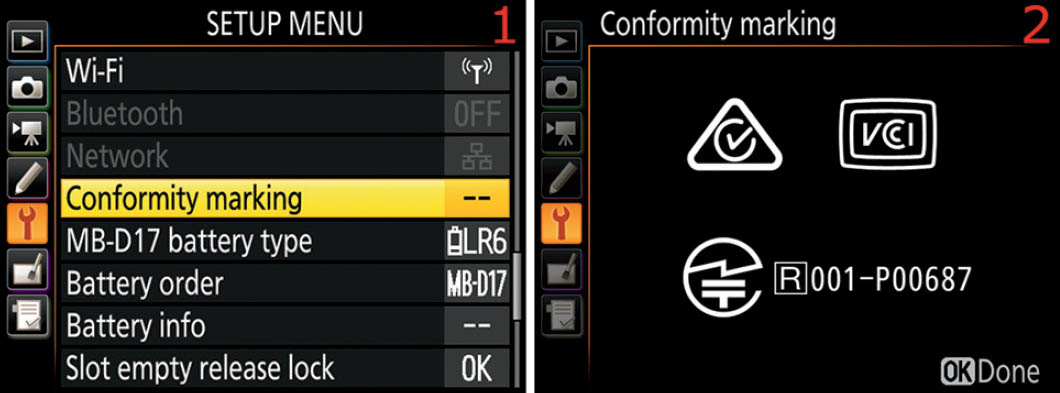
Figure 6.29 – Viewing the symbols for the Nikon D500’s standards conformity
Use the following steps to view the camera’s conformity standards:
- 1. Choose Conformity marking from the Setup Menu (figure 6.29, image 1) and scroll to the right.
- 2. Figure 6.29, image 2, shows the Conformity marking screen with the symbols of conformity. Press the OK button when you are done viewing the symbols.
MB-D17 Battery Type
(User’s Manual: Page 309, Menu Guide: Page 150)
MB-D17 battery type applies only when you choose to use AA-sized batteries of various types in your optional MB-D17 battery pack. It does not apply when you are using normal Nikon EN-EL15, EN-WL18, and EN-EL18a li-ion batteries because they’re intelligent and communicate with the camera.
If you have an MB-D17 and plan on using cheap AA batteries, then you’ll need to tell the camera what type of AA batteries you’re using for this session. It certainly is not a good idea to mix AA battery types.
These are the battery types the camera will accept (figure 6.30, image 2):
- LR6 (AA alkaline)
- HR6 (AA Ni-MH; nickle metal hydride)
- FR6 (AA lithium; Li-ion)

Figure 6.30 – MB-D17 battery type
Here are the steps used to configure the MB-D17 battery type:
- 1. Select MB-D17 battery type from the Setup Menu and scroll to the right (figure 6.30, image 1).
- 2. Choose one of the three choices on the list (figure 6.30, image 2). Press the OK button to lock in the setting.
Settings Recommendation: Nikon allows but does not recommend using certain AA batteries, such as alkaline (LR6). Its primary objection to this type is that they do not work well at lower temperatures. In fact, once the ambient temperature drops below 68 degrees F (20 degrees C), an alkaline battery starts losing its ability to deliver power and will die rather quickly. You may not get as many shots out of a set of AA batteries, so your cost of shooting may rise.
However, AA batteries are readily available and relatively low cost, so some people like to use them, especially in an emergency. If you do choose to use AA batteries, I recommend sticking with lithium types (FR6). That is the same type of cell used in the normal Nikon EN-EL15 batteries and is not affected as much by a low ambient temperature. You can also use the Ni-MH (HR6, nickel-metal hydride) batteries safely because they are not as temperature sensitive and provide consistent power.
Battery Order
(User’s Manual: Page 309, Menu Guide: Page 152)
Battery order lets you choose the order in which you want the available batteries to be used—the camera’s battery first or those in the MB-D17 battery pack first.

Figure 6.31 – Battery order
Here are the steps used to configure the Battery order:
- 1. Select Battery order from the Setup Menu and scroll to the right (figure 6.31, image 1).
- 2. Choose one of the two settings on the list: Use MB-D17 batteries first or Use camera battery first (figure 6.31, image 2). Press the OK button to lock in the setting.
Settings Recommendation: Which battery do you want to draw down first? Personally, I like to use the MB-D17 batteries first and have my camera’s internal battery available as a backup. That way, if I remove the MB-D17, my camera won’t suddenly go dead due to a depleted battery. Nikon thinks the same way, evidently, because the camera defaults to Use MB-D17 batteries first.
Battery Info
(User’s Manual: Page 309, Menu Guide: Page 153)
The Battery info screen (figure 6.32A, image 2) will let you know how much battery charge has been used (Charge), how many images have been taken with this battery since the last charge (No. of shots), and how much life the battery has before it will no longer hold a good charge (Battery age).

Figure 6.32A – Battery info screen
Here are the steps to examine the Battery info:
- 1. Select Battery info from the Setup Menu and scroll to the right (figure 6.32A, image 1).
- 2. The next screen is the Battery info screen. It is just for information, so there’s nothing to set (figure 6.32A, image 2). When you’ve finished examining your camera’s Battery info, press the OK button to exit.
The D500 goes a step further than most cameras. Not only does it inform you of the amount of charge left in your battery, it also lets you know how much life is left. After some time, all batteries weaken and won’t hold a full charge. The Battery age meter will tell you when the battery needs to be completely replaced. It shows five stages of battery life, from 0 to 4, so you’ll be prepared to replace the battery before it gets too old to take many shots.
Battery Info When Using an MB-D17 Battery Pack
If you are using a battery in your MB-D17 battery pack in addition to the one in the camera, the Battery info screen will display as a split screen. The left side of the screen shows information for the battery in the camera, and the right side shows information for the battery in the MB-D17 battery pack (figure 6.32B).

Figure 6.32B – Battery info screen with MB-D17 mounted
Additionally, when you are using a larger Nikon D4 EN-EL18/a battery in the MB-D17, you will see a fourth item—besides Charge, No. of shots, and Battery age—on the Battery info screen. You will see calibration information (not shown). Calibration (CAL) shows up on the screen when the battery needs to be recalibrated with a Nikon MH-26 battery charger. This ensures that the battery’s Charge level can be reported accurately after repeated use and recharging. When Calibration is not required, a long dash (—) will appear instead of CAL.
Settings Recommendation: It’s important to use Nikon brand batteries in your D500 so they will work properly with the camera. Aftermarket batteries may not charge correctly in the D500 battery charger. In addition, they may not report correct Battery age information. There may be an aftermarket brand that works correctly, but I haven’t found it. Instead, I use the batteries designed by Nikon to work with this camera. I am a bit afraid to trust a camera that costs this much to a cheap aftermarket battery of unknown origin.
Slot Empty Release Lock
(User’s Manual: Page 309, Menu Guide: Page 154)
Slot empty release lock defaults to locking the shutter when you try to take an image without a memory card inserted in the camera. By enabling it, you can take pictures without a memory card but cannot save them later.
This function exists so that when you have your camera tethered to your computer using Nikon Camera Control Pro 2 software (not included), you can send pictures directly to the computer, bypassing the memory card.
You can allow the camera to take pictures with no card inserted when you select the OK Enable release setting. Here is a description of both settings:
- LOCK Release locked: When you choose this setting, your camera will refuse to release the shutter when there is no memory card present.
- OK Enable release: Use this setting if you want to use the optional Camera Control Pro 2 software to send images from the camera directly to the computer.

Figure 6.33 – Slot empty release lock
Here are the steps used to configure Slot empty release lock:
- 1. Select Slot empty release lock from the Setup Menu and scroll to the right (figure 6.33, image 1).
- 2. Choose one of the two settings from the list (figure 6.33, image 2). Press the OK button to lock in the setting.
Settings Recommendation: I tried using the OK Enable release setting as an experiment. I found that there is no real reason to use this setting other than when the camera is tethered to a computer. You cannot save the images in the memory buffer to a memory card later.
Save/Load Settings
(User’s Manual: Page 310, Menu Guide: Page 155)
Do you have your D500 set up exactly the way you like it? Have you spent hours and hours reading this book and the User’s Manual, or simply exploring menus, and finally got all the settings in place? Are you worried that you might accidentally reset your camera or that it could lose its settings in one way or another? Well, worry no more! Save/load settings writes configuration settings to the memory card, allowing you to back up camera settings to your computer.
When you have your camera configured to your liking, or at any time during the process, simply use the Save/load settings function to save the camera configuration to your memory card. It creates a 58 KB file named NCSETUPK.BIN in the root directory of your memory card. You can then save that file to your computer’s hard drive and have a backup of your camera settings.

Figure 6.34 – Save/load settings
Here are the steps to save or load the camera’s settings:
- 1. Choose Save/load settings from the Setup Menu and scroll to the right (figure 6.34, image 1).
- 2. Select Save settings or Load settings from the Save/load settings menu, and then follow one of these two easy procedures (figure 6.34, images 2 and 3):
- a. Save settings: Select Save settings and press the OK button (figure 6.34, image 2). Your most important camera settings will be saved to your memory card. Afterward, copy the settings file (NCSETUPK.BIN) to your computer for safekeeping. Warning: You may notice that in the screen displayed in figure 6.34, image 2, the Load settings selection is grayed out on your camera. If Load settings is not grayed out when you get ready to save the settings, be careful—you are about to overwrite previously saved settings that are currently on the memory card. The only time you’ll see Load settings not grayed out is when an NCSETUPK.BIN file already exists on the memory card.
- b. Load settings: Insert a memory card with a previously saved NCSETUPF.BIN file in the card’s root directory, select Load settings, and press the OK button (figure 6.34, image 3). The settings you previously saved will be reloaded into the D500 and will overwrite your current settings without prompting you for permission, so be sure that you are ready to have the settings overwritten. If you change the name of the NCSETUPK.BIN file, the D500 will not be able to reload your settings.
Here is a list of settings that are saved or loaded when you make use of one of these functions. It doesn’t save or load every setting in the D500, only the ones listed here:
Playback Menu (6 settings)
- Playback display options
- Image review
- After delete
- After burst, show
- Auto image rotation
- Rotate tall
Photo Shooting Menu (all four banks included, 21 settings)
- Photo shooting menu bank
- Extended photo menu banks
- File naming
- Primary slot selection
- Secondary slot function
- Flash control
- Choose image area
- Image quality
- Image size
- NEF (RAW) recording
- ISO sensitivity settings
- White balance (includes fine-tuning adjustments and presets d–1 to d–6)
- Set Picture Control (Custom Picture Controls are saved as Standard)
- Color space
- Active D-Lighting
- Long exposure NR
- High ISO NR
- Vignette control
- Auto distortion control
- Flicker reduction
- Auto bracketing set
Movie Shooting Menu (15 settings)
- File naming
- Destination
- Choose image area
- Frame size/frame rate
- Movie quality
- ISO sensitivity settings
- White balance (with fine-tuning settings and all presets d–1 to d–6)
- Set Picture Control (Custom Picture Controls are saved as Standard)
- Active D-Lighting
- High ISO NR
- Flicker reduction
- Microphone sensitivity
- Frequency response
- Wind noise reduction
- Electronic VR
Custom Settings (all four banks included, 52 settings)
- All Custom Settings
- Language
- Time zone and date (except Date and time and Sync with smart device)
- Information display
- Non-CPU lens data
- Clean image sensor
- Image comment
- Copyright information
- IPTC
- Beep
- Touch controls
- HDMI
- Location data (except the Download from smart device option)
- Wireless remote (WR) options
- Assign remote (WR) Fn button
- Eye-Fi upload
- MB-D17 battery type
- Battery order
- Slot empty release lock
My Menu and Recent Settings (up to 41 settings)
- My Menu (includes all items you’ve entered, up to 20 settings)
- All Recent Settings (up to 20 settings)
- Choose tab
Settings Recommendation: This function is a great idea. After using my camera for a few days and getting it set up just right, I save the settings file to my computer for safekeeping. Later, if I change things extensively for some reason and then want to reload my original settings, I just put the backed-up settings file on a memory card, pop it into the camera, select Load settings, and I’m back in business.
Reset All Settings
(User’s Manual: Page 310, Menu Guide: Page 158)
The Reset all settings function allows you to do exactly what it says: reset all the settings within the Nikon D500. At some point in the future, you may want to sell your camera to offset the cost of a new Nikon purchase, or you may just want to start over with fresh settings. This function allows you to do so.

Figure 6.35 – Reset all settings in the Nikon D500
Use the following steps to reset your D500’s menu settings for a fresh start with menu configuration:
- 1. Select Reset all settings from the Setup Menu and scroll to the right (figure 6.35, image 1).
- 2. If you want to reset the camera’s settings, highlight Reset and scroll to the right (figure 6.35, image 2). Choose Do not reset to cancel.
- 3. Choose Yes from the popup screen that asks All settings will be reset. Once reset, settings cannot be restored. OK? Press the OK button and the camera will execute a settings reset. Choose No to cancel.
Firmware Version
(User’s Manual: Page 310, Menu Guide: Page 158)
Firmware version is a simple informational screen, like the Battery info screen. It shows you which version of the camera’s operating system (firmware) the D500 is running. My camera is currently running version C1.02 and LD2.013 (figure 6.36, image 2).
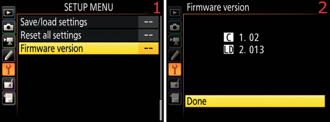
Figure 6.36 – Viewing the camera’s Firmware version
Here are the steps to see the Firmware version of your camera:
- 1. Choose Firmware version from the Setup Menu and scroll to the right (figure 6.36, image 1).
- 2. Examine the Firmware version (figure 6.36, image 2). Select Done and press the OK button.
When it’s time to do a Firmware update, you will use this same Firmware version menu to update the camera. An extra “Update” menu item will appear below the Done selection, allowing you to update the Firmware. Follow the instructions provided on Nikon’s website for each Firmware update.
Author’s Conclusion
Whew! The D500 may seem like a complicated little beast, but that’s what you get when you fold pro-level functionality into a relatively small DSLR body. For as complex as it is, I’m certainly delighted with it.
Next, we’ll consider how to use the camera’s Retouch Menu to adjust images without using a computer. If you are in the field shooting RAW files and you need a quick JPEG, black-and-white version of a file, or red-eye reduction, the Retouch Menu has you covered.
You can even do things like image distortion and perspective control, color balance changes, filtration, cropping, and image resizing—all without touching a computer. Let’s see how!