
Microsoft Vista: Networking Essentials
Introduction
Microsoft Windows Vista includes a number of significantly improved networking technologies that are designed to enhance productivity and security for end users and the corporate environment, as well as simplify the administration process for system administrators. In this chapter, we’ll take a look at some of the new networking technologies in Windows Vista, as well as technologies that have been significantly improved over previous versions of the Windows operating system (OS).
We begin with a discussion of Internet Protocol (IP) version 6, or IPv6. Windows Vista is the first Microsoft OS to provide full support for IPv6 straight out of the box, while still allowing complete interoperability with existing IPv4 networking technologies. We’ll discuss the origins of IPv6, its advantages over IPv4, and how Windows Vista has deployed IPv6 support.
Next, we’ll move on to the new “home” for Windows Vista networking, the Network and Sharing Center. This new interface provides much more streamlined and intuitive access to configuring Windows Vista networking components, and it includes new options for displaying a graphical view of your network infrastructure using the Network Map.
We’ll then spend a good deal of time looking at the Windows Firewall, which has undergone a significant overhaul in Vista, even from the improvements that Microsoft made in Windows XP Service Pack (SP) 2. The Vista Firewall addresses a number of limitations that were present in the XP Windows Firewall, including the ability to monitor and restrict both incoming and outgoing traffic, as well as combining the administration of IP Security (IPSec) and the Windows Firewall to allow the two technologies to work together more smoothly.
Not Your Father’s TCP/IP Stack
Although support has been available for IPv6 in previous versions of the Microsoft OSes, Windows Vista is the first OS to turn on IPv6 straight out of the box. Microsoft did this as part of a belief that IPv6 will begin to play a much greater role on the Internet as more and more devices and applications become a part of the so-called “connected world.” Deploying IPv6 offers a number of benefits for consumers, administrators, developers, and Internet service providers (ISPs) alike. But to fully appreciate these benefits, it’s necessary to take a step back and compare IPv6 against the current de facto IPv4 standard.
Limitations of IPv4
The current implementation of the Transmission Control Protocol/Internet Protocol (TCP/IP), IPv4, has been in use on the Internet since the early 1980s. Although this makes IPv4 something of a dinosaur by technology standards, the current implementation has nonetheless held up quite well under the demands of an exploding Internet population of high-speed consumer connections and e-commerce sites aplenty. However, IPv4 has a number of limitations that we will discuss next. The IPv6 standard has specifically addressed these limitations to improve the security, manageability, and scalability of TCP/IP networks.
Limited Address Space
IPv4 has a much more limited address space than the IPv6 standard. IPv4 has a 32-bit address space, which most of us are familiar with seeing in dotted decimal notation, written like this: 192.168.2.168. What this actually represents is a binary string that is 32 digits long (and thus a 32-bit string), where each of those four numbers is translated into binary. So, an IP address that is expressed using dotted decimal notation as 192.168.2.168 would be represented in binary as follows: 11000000101010000000001010101000.
By using a 32-bit address space, IPv4 has a theoretical upper bound of 4,294,967,296 possible IP addresses. However, the actual number of available IPv4 addresses is limited by some implementation decisions that were made in the early days of IPv4’s use as a protocol. The most striking example of this is the loopback address range, where all IPv4 addresses in the 127.x.x.x space have been reserved for troubleshooting and testing purposes: By making the familiar 127.0.0.1 address available as a troubleshooting tool, the originators of the IPv4 standard eliminated 16,777,216 IP addresses in one fell swoop.
The number of available IPv4 addresses has also been limited by some early decisions in doling out IPv4 IP addresses to various organizations that were early adopters of the Internet. For some historical perspective on this, remember the following: Before the mid-’90s, the Internet was primarily an educational tool that was funded by the National Science Foundation and populated only by large research universities and corporations such as MIT and Bell Labs. Not foreseeing the commercial explosion that would take place with the rise of e-commerce many years later, IP addresses were doled out quite generously to early Internet residents because there seemed no danger of ever running out: A single research university in the United States might have more IP addresses assigned to it than an entire European nation, for example. For both of these reasons, the actual number of available IPv4 addresses is closer to a few million rather than upward of 4 billion.
IPv4 has thus far staved off being relegated to legacy status by the active use of a network address translator, or NAT. This has allowed latecomers to Internet society to conserve the available reserves of IP addresses by relying on private IP addresses for the majority of their networking needs. RFC 1918 defines the following private IP address ranges that have been reserved from the IPv4 space for use by private organizations:
■ 10.0.0.1 through 10.255.255.255
■ 172.16.0.0 through 172.31.255.255
■ 192.168.0.0 through 192.168.255.255
This RFC defined private IP addresses to meet both of the following needs (as noted at www.faqs.org/rfcs/rfc1918.html):
■ “Hosts that do not require access to hosts in other enterprises or the Internet at large; hosts within this category may use IP addresses that are unambiguous within an enterprise, but may be ambiguous between enterprises.”
■ “Hosts that need access to a limited set of outside services (e.g., e-mail, FTP, netnews, remote login) which can be handled by mediating gateways (e.g., application layer gateways). For many hosts in this category an unrestricted external access (provided via IP connectivity) may be unnecessary and even undesirable for privacy/security reasons. Just like hosts within the first category, such hosts may use IP addresses that are unambiguous within an enterprise, but may be ambiguous between enterprises.”
In other words, private IP addresses are intended for use by both personal and business computers that don’t necessarily need to possess a public IP address all their own. These will typically be desktop computers that are being used to access Internet resources such as e-mail, the World Wide Web, and so on, using a NAT device that can provide Internet connectivity under these conditions without expending a public IP address for each connected computer.
NAT to the Rescue?
Devices configured with private IP addresses can communicate on the Internet by using a NAT device such as a router or proxy server. A NAT device will take packets sent from a device configured with a private IP and then, as the name suggests, translate those packets using a public IP address assigned to the NAT device. For example, say that you have a workstation on a corporate network that is configured with the private IP address of 192.168.0.155. This workstation wants to communicate with a Web server on the Internet that is configured with an IP address of 151.4.5.7. When the private computer transmits packets to the destination Web server, the source and destination addresses read as follows:
■ Destination address: 151.4.5.7
■ Source address: 192.168.0.155
The private computer does not transmit these packets directly to the destination Web server, however; the traffic is instead transmitted to a NAT device configured with a public IP address of 217.8.6.5. The NAT device then removes the private source address, replaces it with a public IP address, and then retransmits the packets to the destination host as follows (the NAT device maintains a translation table to keep track of inbound and outbound traffic that it is translating for multiple hosts on the private network):
■ Destination address: 151.4.5.7
■ Source address: 217.8.6.5
When the destination Web server transmits information back to the 192.168.0.155 workstation, the destination address is not the private IP address, but rather the public address of the NAT device. (The destination Web server typically does not even realize that a NAT device is involved in the conversation.) So, the return headers will look like this:
■ Destination address: 217.8.6.5
■ Source address: 151.4.5.7
Based on the information that it recorded in its translation table, the NAT device will receive this information and then translate the destination address to that of the computer on the private network:
■ Destination address: 192.168.0.155
■ Source address: 151.4.5.7
Although the use of NAT has been a boon for conserving available addresses within the IPv4 32-bit space, it is not the panacea that it might seem at first glance. The use of NAT for network applications can create performance issues as packets are bottlenecked into a single NAT device on one or both ends of the communication, and certain applications and protocols do not function reliably (or sometimes at all) if they are required to transmit through a NAT device. For example, many devices are unable to route IPSec-secured traffic (such as that used for a virtual private network [VPN]) through a NAT device because the headers are encrypted, thus rendering NAT unable to modify the source and destination addresses without breaking the encryption process. This has largely been addressed by the use of NAT-Traversal (NAT-T), but this is unfortunately not a universal solution because not all NAT devices conform to a single standard. This “NAT Traversal” problem has also reared its head in the case of peer-to-peer applications used for file sharing and Voice over IP that cannot always communicate through NAT devices.
Security and Quality of Service
Another limitation of IPv4 is a lack of support for built-in security and quality of service (QoS) functionality. Although one can use security measures such as IPSec to secure IPv4 traffic, these technologies are not mandatory and were often vendor-specific or shoehorned onto the IPv4 standard after the fact; this can create havoc in terms of deploying and troubleshooting these security measures, particularly when dealing with heterogeneous networks connected by many different vendor devices.
Another limitation of IPv4 is that it has no built-in mechanism to support QoS. The idea behind QoS is fairly simple: It is a matter of granting priority to certain types of traffic in limited-bandwidth environments. An example here might be found in trying to optimize bandwidth utilization at a research university: As a network engineer, would you rather give priority to Internet traffic being used by a scientist to perform cancer research, or to the resident of an undergraduate residence hall who is downloading a pirated copy of The Matrix 7: Can’t Kill Neo! from a peer-to-peer file-sharing network? (The undergraduate in question might have a different answer to that query than the university network engineer, but that’s another matter.) Similar to security measures for IPv4, QoS is not mandatory for IPv4 traffic, and many current QoS solutions are vendor-specific and are not scalable across the whole of the Internet.
Host and Router Configuration
IPv4 requires quite a bit of manual labor in configuring both host computers and routers on an IPv4 network. In order to communicate over an IPv4 network, all hosts either require a statically assigned IPv4 address or must be able to contact a Dynamic Host Configuration Protocol (DHCP) server to obtain their IPv4 configuration information. To transmit traffic between hosts IPv4 routers require cumbersome methods to “learn” where other routers on the Internet are located; these methods will often involve route advertisements being broadcast across an entire IPv4 subnet.
Introduction to IPv6 and Dual Layer
To alleviate the issues created by the current reliance on the IPv4 standard, the updated IPv6 was introduced in the mid-1990s and was defined in RFC 2460 (www.faqs.org/rfcs/rfc2460.html). IPv6 has thus far had a slow adoption rate for one simple reason: IPv6 is not backward-compatible with IPv4. This means any organization that wants to use IPv6 has had one of the following three fairly unappealing choices:
■ Perform a “hard cut” in which all networked resources were converted from IPv4 to IPv6.
■ Maintain a separate network infrastructure for IPv6-enabled network devices.
■ Invest in network hardware that was both IPv4- and IPv6-capable.
The first two options would be about as welcome as a root canal under any circumstances (particularly because the first option would not address the need to communicate beyond one’s own local network), and hardware that supported both TCP/IP versions was either unavailable or prohibitively expensive in the early days of IPv6. As time has gone on, however, IPv6 has come into broader usage so that supporting a “dual stack” environment is far less distasteful.
In the following sections, we will examine how IPv6 addresses the limitations that were present in the IPv4 implementation of TCP/IP.
Increased Address Space
The most noticeable difference between IPv4 and IPv6 is the massive disparity in the number of available IP addresses. As we mentioned previously, IPv4 uses a 32-bit address space which allows for a theoretical maximum of around 4 billion IP addresses. IPv6, by contrast, uses a 128-bit address space; this allows for 2128 total IP 38 addresses, or 3.4 * 1038 possible IP addresses. This figure represents the scientific notation shorthand for 2128; the exact number is 340,282,366,920,938,463,463,374,607,431,768,211,456 possible IP addresses. Even allowing for future growth, this address space seems nigh-inexhaustible; there are enough available IP addresses in the IPv6 space to assign multiple IP addresses to every man, woman, and child currently living on the planet Earth.
IPv6 addresses contain eight groups of hexadecimal characters separated by colons—for example, 4DAB:FFFF:0000:3E3A:02AA:00FF:DA72:9C5A. You’ll often see the leading zeros in a section suppressed to save space; we could have written the preceding example as 4DAB:FFFF:0:3E3A:02AA:00FF:DA72:9C5A. In cases where more than one hexadecimal grouping consists of all zeros, we can cut these out entirely and replace them with a double colon; so, we could abbreviate fe80:0:0:0:2aa:ff:fe9a:4ca2 as fe80::2aa:ff:fe9a:4ca2.
Built-in Security and QoS
Unlike IPv4, in which security and QoS measures were optional portions of the protocol that were often added in later as protocol extensions, IPSec and QoS are built right into IPv6 and are a mandatory component of each packet. Quality of Service information is encoded into the Flow Label Header field of IPv6 packets, as defined in RFC 3697 (www.faqs.org/rfcs/rfc3697.html).
Windows Vista Support for IPv6
Windows Vista is the first Microsoft OS to support IPv6 natively; it is installed and enabled by default when the OS is first installed. This includes support for a number of IPv6 features, including the following:
■ IPSec support In both Vista and Longhorn, IPSec support under IPv6 is the same as it is for IPv4, including support for the Internet Key Exchange (IKE) protocol as well as IPSec encryption using 128-, 192-, or 256-bit Advanced Encryption Standard (AES) encryption. You can configure IPSec for IPv6 using the IPSec Microsoft Management Console (MMC) snap-in, as well as the new Windows Firewall applet.
■ Link-Local Multicast Name Resolution (LLMNR) The IPv6 RFC defines a number of different classifications of IPv6 IP addresses. Global Unique Addresses, for example, are analogous to public IP addresses in IPv4. But rather than force network administrators to rely only on the public/private classification, IPv6 includes multiple types of local-use addresses that can be used under various circumstances. Site-local addresses correspond most closely to private IP addresses under IPv4; they are not reachable outside of a private site and are not forwarded by any IPv6-capable router. In addition to these two address types, IPv6 also defines link-local addresses, which can be used by nodes on a single network that are not separated by a router. LLMNR allows link-local addresses on a single subnet to resolve each other’s names even without the use of domain name system (DNS) or NetBIOS; this is accomplished by sending a name resolution query to a multicast address to which any LLMNR-capable hosts will respond.
■ IPv6 over PPP The Windows Vista remote access client allows you to configure a Point-to-Point Protocol (PPP) connection using IPv6, as well as providing support for creating L2TP-based VPN connections over IPv6.
■ GUI configuration In Windows XP and Windows Server 2003, you were only able to configure IPv6 from the command line using the netsh command. Windows Vista allows you to configure IPv6 settings through the Properties sheet of a network connection in the Network and Sharing Center, just as you would an IPv4 connection.
Understanding the Dual-Layer Architecture
From the standpoint of the underlying network architecture, Windows Vista’s IPv6 support is fundamentally different from what was implemented in Windows XP and Windows Server 2003. In XP and 2003, IPv6 was implemented in a dual-stack architecture alongside IPv4. This meant that IPv4 and IPv6 were deployed as two entirely separate networking protocols, each with their own Transport and Data Link (framing) layers. This meant, for example, that IPv4 and IPv6 each had their own implementations of the Transmission Control Protocol (TCP) and the User Datagram Protocol (UDP) and never the twain would meet. This also made it more difficult to implement any sort of TCP/IP filtering, because a separate mechanism needed to be implemented for each separate TCP/IP stack. Finally, developers had to do double-duty to write applications that took advantage of both IPv4 and IPv6 because they were implemented using two separate drivers: tcpip.sys and tcpip6.sys.
Windows Vista has completely reengineered this model, replacing the “dualstack” architecture of XP and 2003 with a much improved dual-layer architecture. This means that IPv6 and IPv4 are supported in Windows Vista using a single driver—tcpip.sys—and the two protocols share a common Transport and Framing layer. This allows developers to write applications that can take advantage of both protocols, and it allows network administrators to use the Windows Firewall and IPSec to control both IPv4 and IPv6 traffic simultaneously.
Configuring IPv6 Using the GUI
You can view and modify your computer’s IPv6 settings through the graphical user interface (GUI) by following these steps:
1. Open the Network and Sharing Center.
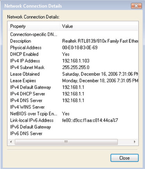
2. Click on View Status, and then click on Details to see a screen similar to Figure 6.1. As you can see, this computer has been automatically configured with an IPv6 link-local address, even though it is not connected to an IPv6-capable network.
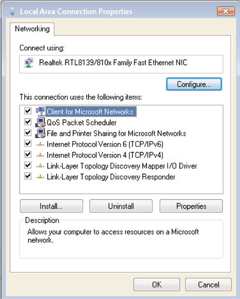
3. Click Close to return to the Connection Status screen. To modify the properties of the IPv6 protocol, click on Properties. If you have User Account Control enabled, you’ll see an additional prompt before being taken to the screen shown in Figure 6.2.
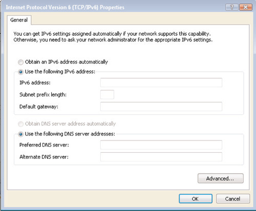
4. To modify the IPv6 configuration, highlight the Internet Protocol Version 6 (TCP/IPv6) option and select Properties. You’ll see the screen shown in Figure 6.3.
Disabling IPv6 Using the GUI
You do not have the ability to uninstall IPv6 from a Windows Vista computer. In addition, if both IPv4 and IPv6 are enabled on a Windows Vista system, Vista will attempt to use IPv6; Windows Vista “prefers” IPv6. An example of this preference is as follows: If a DNS server returns both an IPv6 and an IPv4 record for the same query, Vista will attempt to communicate over IPv6 first. This preference of IPv6 over IPv4 allows for improved network performance in Vista by allowing IPv6 technologies to function more seamlessly.
For the most part, you should not experience any issues with your existing network connectivity as a result of this preference for IPv6; if you are communicating on an IPv4-only network, Vista will not attempt to communicate using IPv6 unless you specify an IPv6-enabled host to which to connect. If you do experience any issues with IPv6 on a Windows Vista system, you can disable it in one of the following ways:
■ Uncheck the Internet Protocol Version 6 (TCP/IPv6) checkbox on the screen shown in Figure 6.2.
■ Modify HKEY_LOCAL_MACHINESYSTEMCurrentControlSetServices cpip6ParametersDisabledComponents using one of the values listed in Table 6.1.
Table 6.1
Disabling Individual IPv6 Components in Windows Vista
| To Disable the Following Feature(s)… | …Enter the Following Value for ~ DisabledComponents |
| Disable all tunnel interfaces | 0x1 |
| Disable 6to4 support | 0x2 |
| Disable ISATAP | 0x4 |
| Disable Teredo | 0x8 |
| Disable Teredo and 6to4 | 0xA |
| Disable all LAN and PPP interfaces | 0x10 |
| Disable all LAN, PPP, and tunnel interfaces | 0x11 |
| Prefer IPv4 over IPv6 | 0x20 |
| Disable IPv6 over all interfaces and prefer IPv4 to IPv6 | 0xFF |
Configuring IPv6 from the Command Line
Similar to IPv6 in Windows XP and Windows Server 2003, Vista offers you the ability to configure IPv6 at the command line using the netsh command. Netsh has several subcommands that you can use to configure an IPv6 IP address, add an IPv6 gateway, and configure IPv6 DNS servers, as well as other configuration options. Let’s look at some of the more common subcommands.
Configuring an IPv6 IP Address
To configure an IPv6 address using netsh, use the following syntax:
netsh interface ipv6 add address “Local Area Connection” 1045:CA8:260C:1291:5AB2:D
To delete an IPv6 IP address, simply repeat the preceding command, replacing the add subcommand with delete.
Configuring an IPv6 Default Gateway
To add a default gateway for an IPv6 command, you use the add route subcommand, which takes the following syntax (we explain the various subcommands in Table 6.2):
Table 6.2
Netsh Options for Adding IPv6 Gateways
| Subcommand | Explanation | Default Value |
| prefix | The IPv6 address prefix and prefix length for the default route | Use ::/ for the default route. |
| interface | The name of the interface or connection that you’re configuring | N/A |
| nexthop | The next-hop IP address (if a nonlocal link) | N/A |
| siteprefixlength | Specifies the prefix length for the site if the destination is on the local link | N/A |
| metric | Specifies a preference if more than one route is available to a particular destination | Routes with a lower metric will be used before routes with a higher one. |
| publish | Specifies whether this route will be included in router advertisements | N/A |
| validlifetime | The lifetime for which a route is preferred | Infinite |
| store | Specifies whether the route is active (is removed from memory when the system restarts) or persistent (remains in memory after a system restart) | Persistent |
netsh interface ipv6 add route [prefix =]::/0
[interface =]Interface_Name_or_Index [[nexthop =]IPv6_Address]
[[siteprefixlength =]Length] [[metric =]Metric_Value] [[publish =]no|yes|immortal] [[validlifetime =]Time|infinite]
[[preferredlifetime =]Time|infinite] [[store =]active|persistent]
At its simplest, the following command will add a default gateway using default values:
netsh interface ipv6 add route ::/0 “Local Area Connection”
FE80::5226:ff:12A9:56CA
Adding IPv6 DNS Servers
Configuring an IPv6 DNS server is very similar to configuring an IP address. To add an IPv6 DNS server, use the netsh interface ipv6 add dnsserver “Local Area Connection” < IPv6 Address > command. Likewise, you’ll use the netsh interface ipv6 delete dnsserver… command to remove a DNS server entry.
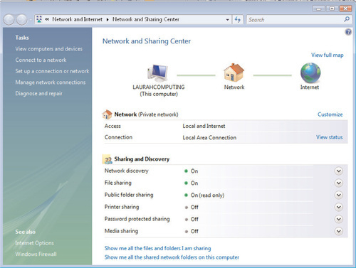
Using the Network and Sharing Center
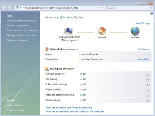
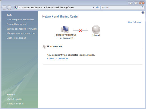
One of the new features in the Windows Vista GUI is the Network and Sharing Center, which replaces the Network Connections applet in the Windows XP Control Panel. The Network and Sharing Center acts as a kind of “one-stop shop” to control many aspects of networking within Windows Vista: configuring and troubleshooting network locations, providing access to network diagnostics, and even providing a graphical Network Map of your existing network layout. (We’ll discuss the Network Map further in the next section.) You can see a typical view of the Network and Sharing Center in Figure 6.4.
Working with Network Sharing and Discovery
To help improve network security, particularly for home-based users, Vista introduces the notion of network locations to help you apply preconfigured security settings to a particular network connection. Network locations help you to configure security for your network by bundling together configuration settings for the networking options discussed in the following sections.
Network Discovery
When Network Discovery is enabled, Vista opens up a number of ports on the Windows Firewall to allow other computers on a network to browse to resources on your computer. Enabling Network Discovery allows you to access files and devices (such as shared printers) on other computers, and allows other network users to access files and devices on your computer. At first glance, this may seem analogous to the Network Browser service in previous versions of Windows. Windows Vista, however, has significantly updated the Network Discovery process and includes a number of new features for resource discovery. One of the most promising is the Function Discovery feature, which is a programming interface that will allow hardware vendors to advertise what type of function a particular device can perform. For example, using Network Discovery might allow a network printer to advertise through Function Discovery that it is capable of producing color output or doublesided printing. Network Discovery also supports the WSDAPI framework, which allows for the use of a secure channel when communicating between a device and a client, as well as the Simple Service Discovery Protocol, which is used to detect Universal Plug and Play (UPnP) devices on a network.
Enabling Network Discovery will open the following inbound ports in the Windows Firewall:
■ Network Discovery (LLMNR-UDP-In) Creates an inbound rule to allow Link Local Multicast Name Resolution on UDP port 5355.
■ Network Discovery (NB-Datagram-In) Creates an inbound rule to allow NetBIOS Datagram transmission and reception on UDP port 138.
■ Network Discovery (NB-Name-In) Creates an inbound rule to allow NetBIOS Name Resolution on UDP port 137.
■ Network Discovery (Pub-WSD-In) Creates an inbound rule to discover devices via Function Discovery on UDP port 3702.
■ Network Discovery (SSDP-In) Creates an inbound rule to allow use of the Simple Service Discovery Protocol on UDP port 1900.
■ Network Discovery (UPnP-In) Creates an inbound rule to allow use of Universal Plug and Play on TCP port 2869.
■ Network Discovery (WSD Events-In) Creates an inbound rule to allow WSDAPI Events via Function Discovery on TCP port 5357.
■ Network Discovery (WSD EventsSecure-In) Creates an inbound rule to allow Secure WSDAPI Events via Function Discovery on TCP port 5358.
■ Network Discovery (WSD-In) Creates an inbound rule to discover devices via Function Discovery on UDP port 3702.
Because the new Windows Firewall in Vista can also monitor and control outbound connections, enabling Network Discovery will enable the following outbound ports in addition to the inbound ports just discussed:
■ Network Discovery (LLMNR-TCP-Out) Creates an outbound rule to allow Link Local Multicast Name Resolution (LLMNR) on TCP port 5355.
■ Network Discovery (LLMNR-UDP-Out) Creates an outbound rule to allow Link Local Multicast Name Resolution on UDP port 5355.
■ Network Discovery (NB-Datagram-Out) Creates an outbound rule to allow NetBIOS Datagram transmission and reception on UDP port 138.
■ Network Discovery (NB-Name-Out) Creates an outbound rule to allow NetBIOS Name Resolution on UDP port 137.
■ Network Discovery (Pub WSD-Out) Creates an outbound rule to discover devices via Function Discovery on UDP port 3702.
■ Network Discovery (SSDP-Out) Creates an outbound rule to allow use of the Simple Service Discovery Protocol on UDP port 1900.
■ Network Discovery (UPnPHost-Out) Creates an outbound rule to allow the use of Universal Plug and Play over TCP (all ports).
■ Network Discovery (UPnP-Out) Creates a second outbound rule to allow use of Universal Plug and Play over TCP (all ports).
■ Network Discovery (WSD Events-Out) Creates an outbound rule to allow for WSDAPI Events via Function Discovery on TCP port 5357.
■ Network Discovery (WSD EventsSecure-Out) Creates an outbound rule to allow for Secure WSDAPI Events via Function Discovery on TCP port 5358.
■ Network Discovery (WSD-Out) Creates an outbound rule to discover devices via Function Discovery on UDP port 3702.
Working with File and Printer Sharing
The basic file- and printer-sharing functionality in Windows Vista has not changed substantially from earlier versions of Windows; enabling File Sharing in the Network and Sharing Center allows other computers to be able to access files and folders that are stored on your local hard drive. Enabling File Sharing will configure the following inbound port exceptions in the Windows Firewall:
■ File and Printer Sharing (Echo Request - ICMPv4-In) This exception allows PING messages to be sent to the local computer from any computer attached to the network using ICMPv4, including those attached to the Internet or other remote networks.
■ File and Printer Sharing (Echo Request - ICMPv6-In) This allows IPv6-enabled computers to send PING messages to the local computer using ICMPv6. This exception is enabled for all network-attached computers, regardless of location.
■ File and Printer Sharing (NB-Datagram-In) This creates an inbound rule to allow NetBIOS Datagram transmission and reception over UDP port 138 from machines on the local subnet.
■ File and Printer Sharing (NB-Name-In) This creates an inbound rule to allow NetBIOS Name Resolution over UDP port 137 from machines on the local subnet.
■ File and Printer Sharing (NB-Session-In) This creates an inbound rule to allow NetBIOS Session Service connections from the local subnet on TCP port 139.
■ File and Printer Sharing (SMB-In) This creates an inbound rule to allow Server Message Block (SMB) transmission and reception via Named Pipes over TCP port 445 from machines on the local subnet.
■ File and Printer Sharing (Spooler Service - RPC) This creates an inbound rule to allow the Print Spooler Service to accept dynamic Remote Procedure Call (RPC) connections over TCP from machines on the local subnet.
■ File and Printer Sharing (Spooler Service - RPC-EPMAP) This creates an inbound rule to allow RPC-EPMAP connections over TCP from the local subnet.
The Windows Firewall also enables the following outbound exceptions when File and Printer Sharing is enabled:
■ Outbound PING traffic, both ICMPv4 and ICMPv6 Outbound Internet Control Message Protocol (ICMP) connections are enabled to all network-connected devices.
■ Outbound NetBIOS and SMB traffic Creates outbound rules for UDP ports 137 and 138, and TCP ports 139 and 445, to machines on the local subnet.
Enabling Printer Sharing
The Network and Sharing Center lists File Sharing and Printer Sharing as two separate options. However, both options enable the same Windows Firewall exceptions, and enabling Printer Sharing automatically enables both File Sharing and Network Discovery. In addition, enabling Printer Sharing creates a \ < computername > print![]() hidden share that maps to ~ Windowssystem32spooldrivers. This share is not removed when Printer Sharing is disabled in the Network and Sharing Center. Additionally, if you turn off Printer Sharing, Network Discovery and File Sharing remain turned on unless you disable them separately.
hidden share that maps to ~ Windowssystem32spooldrivers. This share is not removed when Printer Sharing is disabled in the Network and Sharing Center. Additionally, if you turn off Printer Sharing, Network Discovery and File Sharing remain turned on unless you disable them separately.
Introducing Public Folder Sharing
Public Folder Sharing is a new construct within Windows Vista. Not to be confused with Exchange Public Folders, which are an entirely different entity, Public Folder Sharing creates a single shared document repository on a Vista workstation. This is intended to allow easier shared file access among multiple users of a single computer, as well as users across a small office, home office (SOHO) or other peer-to-peer network. When you enable Public Folder Sharing in the Network and Sharing Center, the following takes place on the local computer:
■ The C:UsersPublic folder is shared out as \ < computername > Public (you can grant the Everyone group either Read or Full Control permissions).
■ The Network Discovery and File and Printer Sharing exceptions are enabled in the Windows Firewall.
You can see an example of Public Folder Sharing configured with read-only network access in Figure 6.5.
Password-Protected Sharing
Password-protected sharing is another new feature in Vista network sharing. This feature does not open any new exceptions within the Windows Firewall; rather, it limits network access to the Public Folder to only users who have a configured username and password on the local computer.
Media Sharing
Enabling the Media Sharing option in the Network and Sharing Center configures the Windows Media Player Network Sharing Service, which requires the following ports and services:
■ Windows Media Player Network Sharing Service (HTTP-Streaming-In) accepts inbound connections on TCP port 10243 from the local subnet.
■ svchost.exe accepts inbound QoS traffic on TCP and UDP port 2177 from the local subnet.
■ The Simple Service Discovery Protocol accepts inbound traffic on UDP port 1900 from the local subnet.
■ wmpnetwk.exe is configured to accept inbound TCP and UDP connections on all ports from the local subnet.
■ The Windows Media Player Network Sharing Service (UPnP-In) accepts inbound TCP traffic on port 2869 from the local subnet.
Working with Network Locations
When Vista detects that you’ve connected to a new network, such as when you first install or upgrade to Vista or connect to a new wireless network, you will be prompted to select from a set of preconfigured network locations. Vista offers the following preconfigured locations to allow users to quickly configure their network settings in a secure fashion:
■ Home or Work (Private network) In a private network, Vista enables Network Discovery and Password-Protected Sharing within the Network and Sharing Center, because the assumption is that this is a trusted network that is being protected by a firewall, proxy server, or similar device.
■ Public (Public network) Choose this option for airports, coffee shops, and other public locations, or if you are directly connected to the Internet. Under this option, only Password-Protected Sharing is enabled; Network Discovery, File and Printer, Public Folder Sharing, and Media Sharing are all disabled.
To quickly reconfigure a network connection from Public to Private or vice versa, do the following:
1. Open the Network and Sharing Center.
2. Click Customize. You’ll see the screen shown in Figure 6.6.
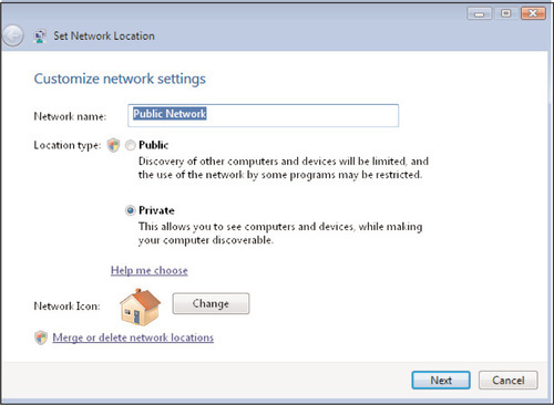
3. Next to Location type, select the radio button corresponding to a Public or Private network, and then click Next, followed by Close.
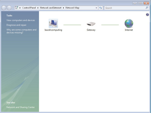
Using the Network Map
Another new feature in the Network and Sharing Center is the Network Map, which provides a graphical view of your local computer’s relative position on the network, as well as indicates any networked computers that have been configured for Network Discovery and/or File and Printer Sharing. For example, Figure 6.7 shows the Network Map on a single-computer network, the kind you might see on a home computer that’s attached to a high-speed Internet connection such as a cable modem.
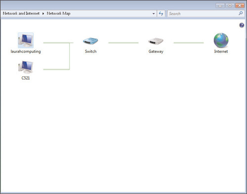
In Figure 6.8, you can see how the Network Map changes if multiple computers are configured for Network Discovery from a private network location. (The Network Map function is not available if the network location is configured as a public network.)
Troubleshooting with the Network Map
Another useful feature of the Network Map is its capability to provide a graphical interpretation of various issues that you may encounter when working with networking in Windows Vista. If a particular network segment becomes disconnected, it will be displayed on the Network Map with a red X over the segment. This can be a great help in troubleshooting, as the Network Map can often indicate where a particular fault has occurred. For example, look at the Network Map in Figure 6.9, in which the network cable for the LAURAHCOMPUTING computer has become unplugged from the switch. You can clearly see by the location of the red X that the fault lies in the connection between the LAURAHCOMPUTING computer and the Internet.
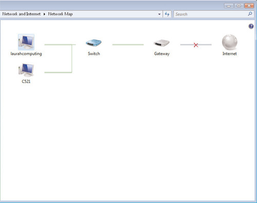
Now let’s look at another troubleshooting scenario and how it is displayed in the Network Map. In this case, we have two computers configured in a peer-to-peer network behind a SOHO router, but the router has lost its connection to the outside world. Figure 6.10 shows you how this might look in the Network Map; you can see that LAURAHCOMPUTING and C521 have connectivity with one another, but that there is a fault somewhere between the local switch and the outside world.
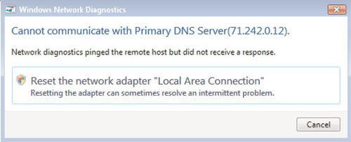
The Network and Sharing Center also offers options to diagnose and repair issues with network connectivity, such as those shown in Figures 6.9 and 6.10. Say, for example, that Internet connectivity has been restored to the network in Figure 6.10, but the LAURAHCOMPUTING machine is still unable to connect to the Internet. Simply click on Diagnose and Repair from the Network and Sharing Center, and quite often Windows Vista will offer a suggestion to correct the issue— not to mention the ability to perform the fix automatically. In this case, Figure 6.11 indicates the cause of the continued connectivity issue and offers to implement a solution.
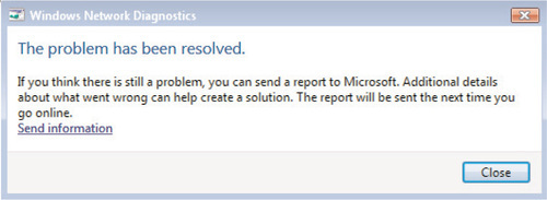
If the troubleshooting measure was successful, you’ll be greeted with the screen shown in Figure 6.12.
Working with the Windows Firewall
You can find another significant update to Windows Vista within the Windows Firewall, in which Microsoft has taken the improvements made in Windows XP SP2 and improved upon them even further. Before we examine the new firewall features available with Vista, though, let’s take a moment to look at the introduction of the Windows Firewall within the Windows XP OS.
With the release of Windows XP SP2, information technology (IT) professionals saw a huge leap forward in Microsoft’s desktop security strategy with the addition of the Windows Firewall. In some ways, the Windows Firewall was a natural progression from the Internet Connection Firewall (ICF) that had been bundled into XP since its original release, but in most respects, the Windows Firewall was a huge departure from earlier Microsoft desktop security mechanisms. The ICF was turned off by default on new XP installations, so many users didn’t even realize it existed. And those people who manually enabled ICF often found that it was difficult to use and configure. This was particularly the case for system administrators because the ICF was not configurable across an enterprise; the only Group Policy setting associated with ICF was the ability to disable it en masse.
The release of the Windows Firewall in XP SP2 presented a much broader range of options for securing the Windows desktop, particularly for Active Directory administrators who wanted to deploy a consistent firewall configuration across an enterprise. Most prominently, the SP2 upgrade process would prompt the user to turn on the Windows Firewall when the install was completed, and the Windows Firewall was turned on out of the box on computers that were preinstalled with SP2. This configuration eliminated many instances of the “My computer got compromised in the time it took me to go out to Windows Update and get my patches” phenomenon that had previously plagued end users and system administrators. The Windows Firewall also added dozens of configurable settings within Group Policy. For example, administrators can use Group Policy to specify which applications or ports to open and whether connections to those resources must be secure, all within the new Windows Firewall with Advanced Security Group Policy node. Group Policy allows administrators to exert granular control of its configuration across an entire organization or a single subset of users. Windows Vista takes this a step further by introducing the Windows Firewall with Advanced Security.
Configuring the Windows Firewall
Similar to the Windows XP firewall, the Windows Firewall with Advanced Security is a stateful, host-based firewall that you can configure to allow or disallow traffic that is generated by either a particular executable file, such as C:Program FilesMicrosoft SQL Serversqlserver.exe, or traffic that is destined for one or more TCP or UDP ports, such as TCP port 80 for Hypertext Transfer Protocol (HTTP) traffic. You’ll find that basic firewall configuration tasks haven’t changed much between Windows XP and Windows Vista; you’ll continue to make these changes using the Windows Firewall Control Panel applet. But even this piece has been updated to make it more intuitive and informative for the end user: When you open the Windows Firewall applet, the first thing you see is a summary of your current Windows Firewall settings, as shown in Figure 6.13.
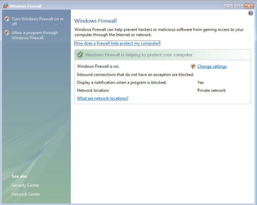
As you can see, this provides an at-a-glance summary of the current state of the firewall; whether it is turned on or off, how exceptions and notifications are being handled, and the network location to which the computer is currently connected. By clicking on Change settings, you’ll be taken to a familiar-looking interface that will actually allow you to make changes, as shown in Figure 6.14.
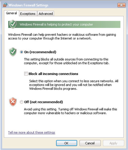
Similar to Windows XP, we define the three settings on the General tab as follows:
■ On (recommended) This is the recommended setting and is enabled by default when Vista is installed. This will block any unsolicited incoming communication attempts that are made against the Vista workstation. All outbound traffic will still be permitted, and any inbound responses to outbound traffic that was initiated by the user will also be permitted. On the Exceptions tab, you can still define exceptions for inbound traffic that should be permitted.
■ Block all incoming connections By placing a checkmark here, you will instruct the Windows Firewall to block all unsolicited connection attempts even if exceptions are defined on the Exceptions tab. You should select this option if you are connected to a public or otherwise insecure network such as one in a hotel, airport, or coffee house, or if a known virus or worm is spreading across the Internet and you want to be extra careful until the threat has largely run its course. When you remove the checkmark next to this option, any traffic defined on the Exceptions tab will once again be permitted to connect to the Vista workstation.
■ Off (not recommended) Microsoft does not recommend this setting for obvious reasons, as it leaves the workstation vulnerable to hackers and malicious software. The only reason you might want to turn off the Windows Firewall would be if you or your organization has already standardized on a third-party software firewall such as the ones offered by Symantec, McAfee, and others.
The Advanced tab in the Control Panel applet has had most of its functionality removed relative to Windows XP SP2. In XP SP2, the Advanced tab allowed you to configure settings for firewall logging, allowing or disallowing inbound ICMP traffic, and creating exceptions on a per-interface basis. As you can see in Figure 6.15, the Advanced tab in the Vista firewall only allows you to do the following:
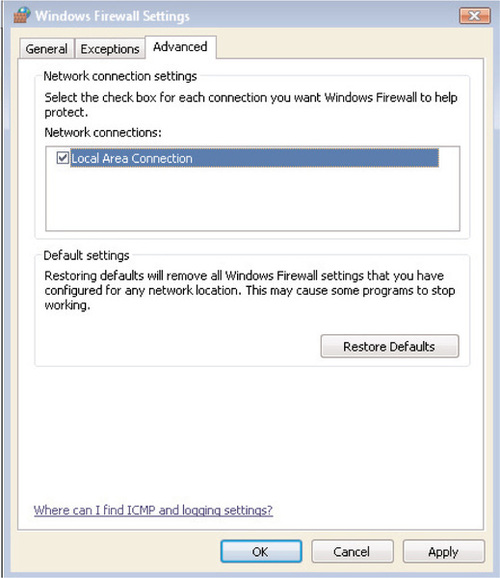
■ Enable or disable the firewall on each installed network interface
■ Restore the Windows Firewall to its default settings
Working with Built-In Firewall Exceptions
In Figure 6.16, you can see the Exceptions tab of the Windows Firewall Control Panel applet. Windows Vista has improved this tab by offering a much wider array of preconfigured firewall exceptions, including the following:
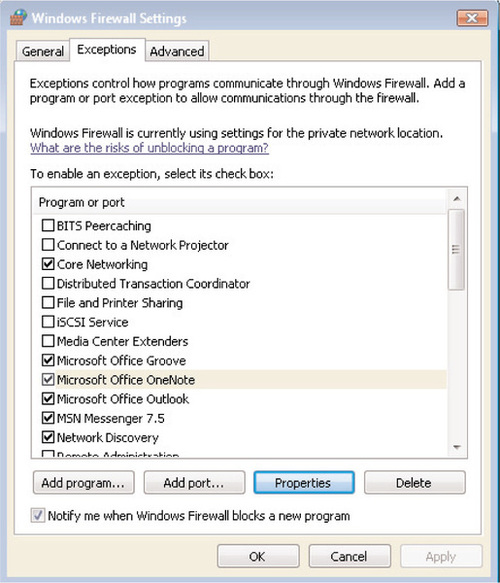
■ BITS Peercaching Allows workstations in the same subnet to locate and share files from the Background Intelligent Transfer Service (BITS) cache using the WSDAPI framework.
■ Connect to a Network Projector The Windows Firewall allows users to easily connect to projectors over wired or wireless networks using WSDAPI.
■ Core Networking This allows for basic inbound and outbound network connectivity over wired and wireless connections.
■ Distributed Transaction Coordinator Coordinates transactions that update transaction-protected resources such as databases, message queues, and file systems.
■ File and Printer Sharing Used for sharing local files and printers with other users. File and Printer Sharing still relies on NetBIOS, SMB, and RPC to communicate.
■ iSCSI Service Used for connecting to iSCSI target servers and devices.
■ Media Center Extenders Allows Media Center Extenders to communicate with a computer running Windows Media Center.
■ Network Discovery As we discussed earlier in this chapter, this feature allows a Windows Vista device to discover other devices and be discovered by other devices on the network using SSDP, Universal Plug and Play, NetBIOS, and LLMNR.
■ Remote Administration This allows administrators to connect remotely to the local computer using interfaces such as the Computer Management MMC snap-in, as well as familiar administrative hidden drive shares such as \computernamec![]() .
.
■ Remote Desktop Allows a remote user to connect to the Vista desktop using the Remote Desktop client over TCP port 3389.
■ Remote Event Log Management Allows remote viewing and management of the local event log using Named Pipes and RPC.
■ Remote Scheduled Task Management Allows remote management of the local task scheduling service over RPC.
■ Remote Service Management Allows remote management of local services using Named Pipes and RPC.
■ Remote Volume Management Provides the ability to manage software and hardware disk volumes remotely over RPC.
■ Routing and Remote Access Creates exceptions to allow incoming VPN and Remote Access Server (RAS) connections.
■ Telnet and Telnet Server Remote Administration Creates a firewall exception to allow remote administration using telnet on TCP port 21.
■ ■Windows Collaboration Computer Name Registration Service Allows other computers to locate and communicate with the local computer using the Peer Name Resolution Protocol and SSDP.
■ Windows Firewall Remote Management Allows for remote management of the Windows Firewall over RPC.
■ Windows Management Instrumentation (WMI) Allows system administrators to retrieve and modify configuration information about the local PC using a standard set of classes and components.
■ Windows Media Player Allows users to receive streaming media using UDP.
■ Windows Media Player Network Sharing Service Allows users to share media using UPnP and SSDP.
■ Windows Meeting Space Creates an exception to allow users to share desktops, programs, and documents over the network.
■ Windows Peer to Peer Collaboration Foundation Creates a common framework to allow various peer-to-peer application traffic to pass through the Windows Firewall.
■ Windows Remote Management Allows remote management of a Vista system using WS-Management, which is a Web services-based protocol that allows for remote management of operating systems and devices.
■ Wireless Portable Devices Allows users to transfer media from a networked camera or other media device using the Media Transfer Protocol (MTP). This exception relies on UPnP and SSDP to function.
Creating Manual Firewall Exceptions
In addition to the built-in firewall exceptions we just discussed, you can also create additional firewall exceptions to allow inbound traffic to pass through the Windows Firewall. In many cases, these manual exceptions will be created automatically by the installer for a particular program, or else you’ll need to manually specify them from the Exceptions tab. The two types of exceptions you can create are as follows:
■ Port exceptions These exceptions allow all incoming traffic destined for particular TCP or UDP ports; for example, you can create an exception to allow incoming traffic on TCP port 80 for HTTP traffic, or on UDP port 69 for Trivial File Transfer Protocol (TFTP) traffic.
■ Program exceptions These exceptions allow all incoming traffic that is destined for a particular executable file running on the local workstation, which will typically correspond to a service running on the local computer. To understand the difference between a port exception and a program exception, let’s look at the example of creating an exception for sqlserver.exe, the executable file associated with Microsoft SQL Server, versus opening an exception for TCP port 1433, which is the default TCP port that SQL Server uses. By creating an exception for sqlserver.exe, the Windows Firewall will allow incoming traffic only when the SQL Server service is actually running; if you stop the service to perform an application upgrade or database maintenance, the Windows Firewall will not accept incoming Structured Query Language (SQL) traffic while the application is not running. By contrast, creating a port exception for TCP 1433 will create an “always on” exception; the Windows Firewall will accept traffic from port 1433 regardless of whether the SQL Server service is running.
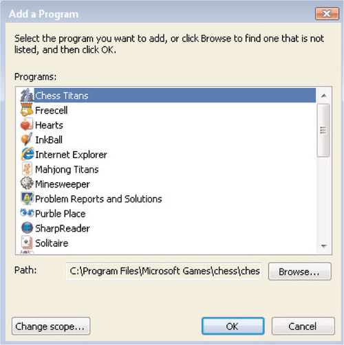
To create a program exception, click on Add program from the Exceptions tab. You’ll see the Add a Program screen shown in Figure 6.17. Click on Browse to select the executable file for which you want to create an exception and then select Open.
By default, any new exception that you create will be accessible by any computer, including those on the Internet. To restrict the scope of an exception that you’ve created, click on the Change scope button. You’ll be presented with the screen shown in Figure 6.18, which will allow you to set one of the following three scopes:
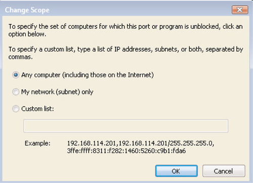
■ Any computer (including those on the Internet) This scope will allow any computer on any network to access this program, including computers located anywhere on the Internet.
■ My network (subnet) only For example, if your workstation has an IP address of 192.168.1.100 and a subnet mask of 255.255.255.0, the exception will be accessible by a machine with an IP address of 192.168.1.1 through 192.168.1.254.
■ Custom list Here you can specify a list of individual IP addresses or ranges and their associated subnet masks; separate multiple entries with commas. For example, you can allow an exception for an entire range of clients plus an administrative workstation as follows: 192.168.1.146/255.255.255.255, 192.168.2.0/255.255.255.0.
Unfortunately, there isn’t a good way to specify a range of addresses that does not correspond to a subnet mask; if you want to allow an exception for 192.168.1.152 through 192.168.1.159, you will need to specify each IP address individually.
To create a port exception, you’ll likewise click the Add port button when creating the exception; you’ll see the screen shown in Figure 6.19. Creating a port exception requires the following information:
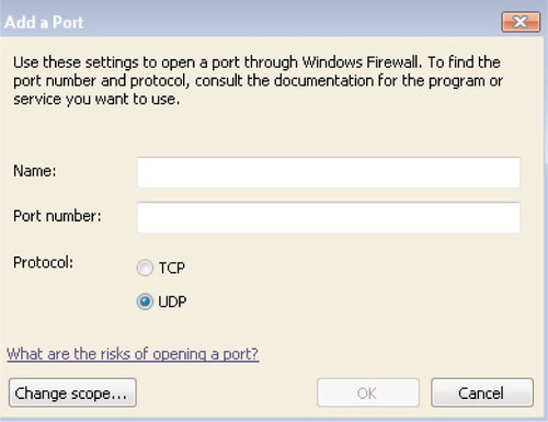
■ Name A descriptive name for the exception, such as “HTTP”, “WSUS Administration Port”, and so on.
■ Port The port number of the exception.
■ TCP/UDP Whether the exception corresponds to a TCP port or a UDP port.
■ Scope By clicking the Change scope button, you’ll specify the scope of the exception just as you would for a program exception.
Advanced Configuration of the Windows Firewall
Unlike the Windows Firewall in XP SP2, you cannot modify the scope or properties of the preconfigured Windows Vista exceptions from the Control Panel applet, as you can see in Figure 6.20. However, there is a new interface for more advanced configuration of the firewall through an MMC snap-in, called Windows Firewall with Advanced Security. This new snap-in provides a number of new features that were not previously available in the XP firewall, including the following:

■ Controlling outbound as well as inbound traffic. The inability to control outbound traffic was a major criticism of the Windows Firewall in XP SP2, which was limited in functionality to controlling inbound traffic only.
■ Configuring the Windows Firewall on remote computers. This feature allows you to attach to a remote computer and configure the firewall from within the Windows Firewall with an Advanced Security snap-in.
■ Integrating Windows Firewall functionality with IPSec. You can now control and administer both of these features from within the same MMC snap-in to avoid conflicts between them.
■ Configuring Authenticated IPSec Bypass, a feature that allows IPSec- authenticated computers to bypass firewall rules that would otherwise block incoming or outgoing connection attempts.
■ Creating and configuring separate firewall profiles based on whether a computer is attached to a private network or a corporate domain versus attaching to a public network in an airport, coffee shop, and the like. The XP SP2 firewall allowed for only two profiles—Domain and Standard— which did not allow the level of granularity that is often required for mobile computers and traveling workers.
You can access the new Windows Firewall with Advanced Security applet from the Administrative Tools menu, or by opening a blank MMC console and clicking on File | Add/Remove Snap-In. You can see the opening screen of the new snap-in in Figure 6.21. As you can see, this snap-in provides a very different view of the Windows Firewall. The left-hand and right-hand panes provide you quick access to perform common tasks and to access different portions of the snap-in, such as viewing inbound rules, outbound rules, connection security rules, and firewall monitoring.
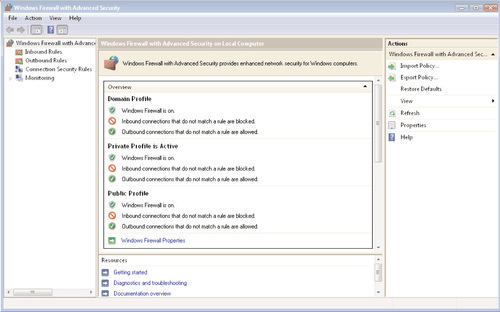
The main screen of the snap-in provides an at-a-glance view of the three available firewall profiles, as well as a visual indicator of which profile is active. The Vista firewall allows you to create different firewall settings for the following profiles:
■ The Domain Profile is active whenever the computer is attached to a corporate Active Directory domain.
■ The Private Profile is active when the computer is attached to a private network.
■ The Public Profile is active when the computer is attached to a public network.
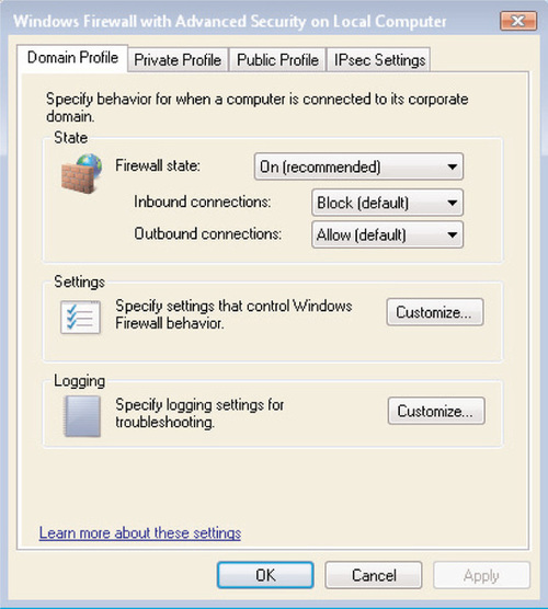
As you can see from Figure 6.21, the default Windows Firewall settings are similar for all three profiles: The Windows Firewall is turned on, inbound connections that do not have a defined exception are blocked, and all outbound traffic is permitted. To customize this default behavior for one or more profiles, click on the Windows Firewall Properties link; you’ll see the screen shown in Figure 6.22. From here, you can change the firewall state from on to off, and change the behavior for inbound and outbound connections. You can change the behavior for inbound connections to one of the following:
■ Block Blocks any inbound connection attempt that doesn’t have an exception associated with it. This is the default setting for inbound connections on all three profiles.
■ Block all connections Blocks all incoming connection attempts regardless of whether there is a rule associated with them; this corresponds to the Block all incoming connections checkbox in the Windows Firewall Control Panel applet.
■ Allow This setting allows any inbound connection attempt.
You can set the behavior for outbound connections to Allow (the default for all three profiles) or Block, which will block outbound traffic unless a rule has been created to allow it.
Clicking Customize under the Settings header will allow you to configure the following:
■ Whether to display a notification when Windows Firewall blocks an incoming connection. By default, notifications are enabled in all three profiles.
■ Whether to allow a unicast response to broadcast or multicast traffic. This is permitted by default in all three profiles. Disabling this feature will not interfere with the operation of a DHCP server, as the Windows Firewall will always permit responses to DHCP messages. However, disabling this feature will interfere with many network discovery protocols, such as NetBIOS, SSDP, and WSDAPI.
Clicking Customize under the Logging header will allow you to configure these settings:
■ The name, size, and location of the Windows Firewall logfile. By default, this file is located at %systemroot%system32LogFilesFirewallpfirewall.log and has a maximum size of 4,096 kilobytes.
■ Whether to log dropped packets and/or successful connections within the Windows Firewall logfile. By default, neither dropped packets nor successful connections are logged within the Domain, Public, and Private profiles.
Modifying IPSec Defaults
The final tab that you see in Figure 6.22 is the IPsec Settings tab; this tab allows you to configure the settings IPSec uses to establish secured connections, as well as whether ICMP traffic should be exempted from IPSec rule processing. These advanced options allow you to configure the default manner in which IPSec handles key exchange, data protection (integrity and encryption), and authentication settings to meet the needs of your network.
By default, IPSec exemptions for ICMP are turned off; however, you may want to enable these exemptions to allow for troubleshooting of network connectivity by allowing PING and TRACERT traffic to pass through the Windows Firewall. By clicking Customize from the IPsec Defaults header, you can customize the default behavior of IPSec from the screen shown in Figure 6.23.
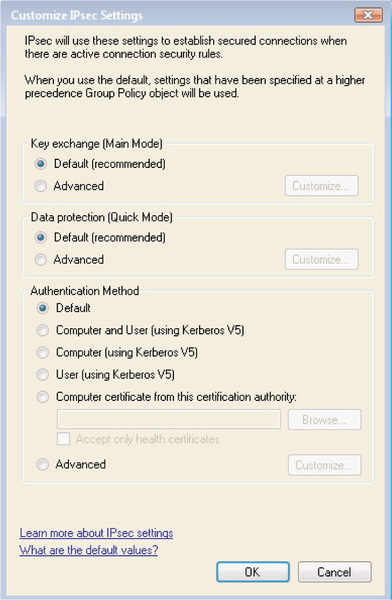
From here, you can customize IPSec’s default behavior in several areas, as we discuss in the following sections.
Key Exchange (Main Mode)
IPSec key exchange is used to establish authentication and data encryption between two computers. This process is divided into two phases: Main Mode and Quick Mode. In Main Mode, the two computers that are communicating use the IKE protocol to set up a secure, authenticated channel between them. This process creates a Main Mode security association (SA). You’ll sometimes also hear this referred to as a Phase I SA. The settings that you define here will apply to all IPSec connection security rules that you create (we’ll discuss connection security rules next); the default settings that are used to create a Main Mode SA are as follows:
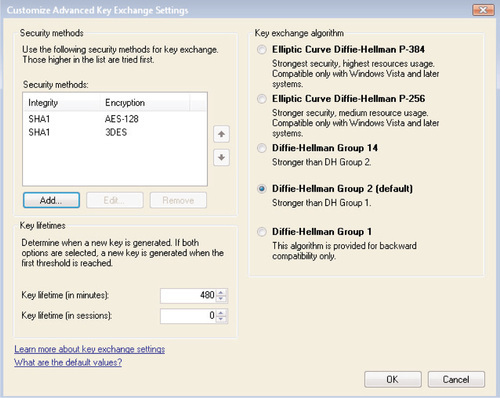
■ Key lifetime (minutes) 480 minutes.
■ Key lifetime (sessions) 0. Having a key lifetime of zero sessions forces any new keys to be issued in accordance with the Key lifetime (minutes) setting only.
■ Key exchange algorithm Diffie-Hellman Group 2.
■ Security methods (integrity) IPSec security methods include both integrity algorithms and encryption algorithms. You can use any combination of these algorithms in order to secure the key exchanges. You can have as many of these combinations as you want, arranged in whatever order you want. These combinations of integrity and encryption algorithms will be attempted in the order that you’ve specified; the first combination that is supported by both peer computers will be the one that is used. If the computers are not capable of using any of the combinations that you’ve defined for IPSec, the two computers will not be able to communicate using IPSec. The default security method used for data integrity is SHA-1.
■ Security methods (encryption) AES-128 is the primary method, and 3-DES (Triple DES) is the secondary method.
Either you can accept the defaults for Main Mode key exchange, or you can select Customize to manually specify any of the settings we’ve described here. Figure 6.24 illustrates the Properties screen where you can modify any of these settings.
Data Protection (Quick Mode)
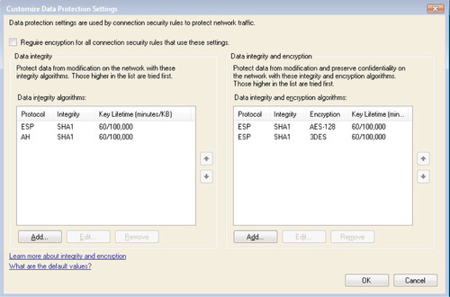
Phase 2 of the IKE process provides for the integrity and/or encryption of the data that’s being transmitted between two computers that have established a Main Mode SA. The default settings for IPSec Quick Mode are as follows:
■ Data Integrity To provide data integrity only within Quick Mode (instead of providing both integrity and encryption), IPSec will first attempt to use the Encapsulating Security Payload (ESP) combined with the SHA-1 data integrity protocol to protect each packet. If ESP protection fails, IPSec will then use the Authentication Header (AH) protocol combined with SHA-1 to protect each packet. When using this method, IPSec does not incorporate any encryption algorithms such as AES or 3-DES. In both cases, the Quick Mode key lifetime is 60 minutes or 100,000 kilobytes of data transmitted, whichever comes first.
■ Data Integrity and Encryption To provide for both data integrity and encryption, IPSec will first attempt to communicate using ESP combined with SHA-1 for data integrity and AES-128 for data encryption. If this connection attempt fails, IPSec will attempt to communicate using ESP, SHA-1, and 3-DES encryption. The key lifetime is the same as before: 60 minutes/100,000 KB.
Again, you can either accept the defaults for IPSec Quick Mode, or select Customize to manually specify any of the settings we’ve described here. Figure 6.25 illustrates the Properties screen where you can modify any of these settings.
Authentication Method
The authentication method settings that you select here will determine how two computers will authenticate one another in order to create an IPSec SA. The default authentication method is Computer (using Kerberos V5), but you can choose any of the following preconfigured methods:
■ Computer and User (using Kerberos V5) This authentication method requires both computer and user authentication, which means that both the user and the computer must authenticate successfully in order for the two computers to communicate. You can use this option to configure domain isolation, which will create a requirement that any incoming connections to the local computer originate only from domain-joined computer or user objects.
■ Computer (using Kerberos V5) This method requires only the computer account to authenticate before communication can take place; the computer must be a part of the same Active Directory domain or in a separate domain that has a trust relationship configured. This option creates domain isolation by only allowing incoming connection attempts from domain-joined computers.
■ User (using Kerberos V5) Similar to the preceding method, this method requires authentication from the user who is logged on to the remote computer; the user must belong to the same Active Directory domain or a trusted domain. This option creates domain isolation by only allowing incoming connections from Active Directory user accounts in the same domain or in a trusted domain.
■ Computer certificate from this certification authority This method will authenticate computers using certificates issued by a particular certificate authority (CA). This method is useful if you need to allow IPSec traffic to nondomain-joined computers or computers that are members of nontrusted Active Directory domains. You can further specify that this method will accept only health certificates, which the Network Access Protection (NAP) service uses to confirm that a computer that is requesting a connection is up-to-date on patching, antivirus, and other health checks that are required for access to the network.
By clicking on Advanced | Customize, you can configure a custom combination of authentication methods; Figure 6.26 illustrates the settings that you can configure in this way.
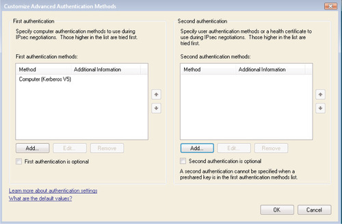
The First authentication method describes how the computer account is authenticated, and the Second authentication method describes user authentication. As you can see, you can specify that one of these steps is optional; user-only authentication would use Second authentication only, for example. When you click Add within the First authentication section, you see the screen shown in Figure 6.27.
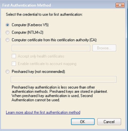
When creating a custom method for computer authentication, you can select from one of the following options:
■ Computer (Kerberos V5) This is the default method for First authentication and will authenticate a computer in the same or in a trusted domain using Kerberos V5.
■ Computer (NTLMv2) This method is used for backward compatibility and to provide authentication for nondomain-joined PCs or PCs joined to untrusted domains.
■ Computer certificate from this certification authority (CA) This method will authenticate computers using certificates issued by a particular CA. You can further control this method by selecting one or both of the following:
Accept only health certificates This will accept only certificates that the NAP process utilizes.
Enable certificate to account mapping This allows you to map a certificate to one or more computer accounts within Active Directory, thus allowing you to use a single certificate for a group of computers.
■ Preshared key (not recommended) This is the least secure authentication method and Microsoft does not recommend it; it is present only for backward compatibility and to ensure compliance with the RFC standards for IPSec. If you configure a preshared key as the First authentication method, you cannot use any method for Second authentication.
Figure 6.28 illustrates the options available when creating a custom method for Second authentication. Similar to First authentication, you can create a custom user authentication method by selecting one of the following:
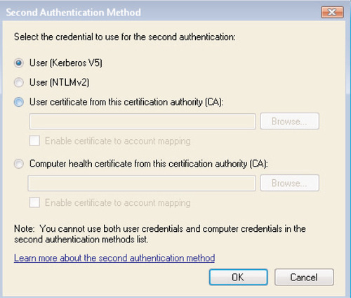
■ User (Kerberos V5) This is the default method for Second authentication and can authenticate any user in the local domain or in any trusted domain.
■ User (NTMLv2) This method exists for backward compatibility and to authenticate nondomain-joined users.
■ User certificate from this certification authority (CA) This method will authenticate users using certificates issues by a particular CA. You have the option to enable certificate-to-account mapping in order to use a single certificate to authenticate one or multiple users.
■ Computer health certificate from this certification authority (CA) Allows you to authenticate using computer health certificates used by the NAP service. You again have the option to enable certificate-to-account mapping of NAP health certificates.
Creating Connection Security Rules
Once you’ve configured the default IPSec behavior for your individual computer or for an entire network, you can create connection security rules that will define how the Windows Firewall with Advanced Security will enforce authentication requirements for different situations. You can view any existing rules by clicking on Connection Security Rules from the main screen of the MMC snap-in. If you right-click on Connection Security Rules, you can view only a subset of these rules, filtered in one of two ways:
■ Filter by Profile will show only those rules that have been configured for the Domain, Private, or Public profile. Selecting Show All will remove any filters.
■ Filter by State will show only those rules that are currently enabled or disabled. Again, selecting Show All will remove any filters and display all defined rules.
To create a new rule, right-click on Connection Security Rules and select New Rule. You’ll see the screen shown in Figure 6.29. You can create one of the following types of connection security rules; we will discuss each one in turn:
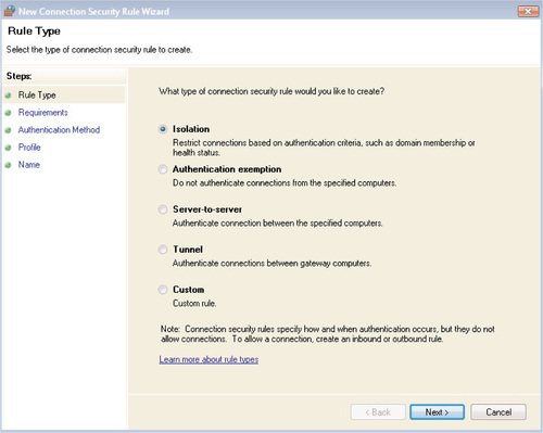
■ An isolation rule will restrict connections to one or more computers based on authentication criteria, by using domain memberships, certificates issued by a CA, or network health certificates issued by NAP.
■ An authentication exemption rule will allow a connection to take place without attempting to authenticate the two computers involved.
■ A server-to-server connection security rule will authenticate a connection between two specific computers.
■ A tunnel connection security rule will authenticate connections between two gateway computers—for example, two computers that are being used to configure a site-to-site VPN.
■ A custom connection security rule will allow you to define the exact parameters that the rule should abide by, if one of the preconfigured choices is not appropriate.
Configuring an Isolation Rule
To configure an isolation connection security rule, select Isolation from the screen shown in Figure 6.29 and then click Next. You will then be prompted to select one of the following three authentication requirements for the new isolation rule:
■ Request authentication for inbound and outbound connections
■ Require authentication for inbound connections and request authentication for outbound connections
■ Require authentication for inbound and outbound connections
Once you have made your choice, click Next. You will then be prompted to select the authentication method that this rule should use. Choose among the following:
■ Computer and User (Kerberos V5).
■ Computer (Kerberos V5).
■ Computer Certificate. If you select this option, you will be prompted to enter the name of a CA on your network. You will also have the option to accept only NAP health certificates.
■ Advanced. If you select this option, you will be prompted to configure a custom authentication method as described in the “Authentication Method” section, earlier in this chapter.
Once you have made your choice, click Next. You will then be prompted to select which Windows Firewall profile will apply this rule: Domain, Public, and/or Private. You can configure this rule to be enforced under one, two, three, or none of the Windows Firewall profiles.
Click Next to continue. You’ll be prompted to enter a name and an optional description for this rule. Click Finish when you’re done. You’ll be returned to the main MMC snap-in window, where you will see the newly created rule listed in the main window. From here, you can right-click on the rule to disable or delete it, or you can select Properties to modify any of the settings that you configured in the wizard.
Configuring an Authentication Exemption Rule
To create an authentication exemption rule, perhaps for a destination computer that does not support IPSec or that needs to be made available to public-facing clients, select Authentication Exemption from the screen shown in Figure 6.29 and click Next.
Click Add to configure the list of computers that should be exempt from IPSec authentication; you’ll see the screen shown in Figure 6.30. You can configure exemptions for one or more single IP addresses, for a range of IP addresses, or for one of the following predefined sets of computers:
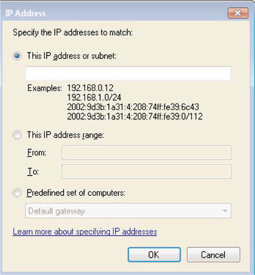
■ Windows Internet Name Service (WINS) servers.
■ DHCP servers.
■ DNS servers.
■ Local subnet. This includes all computers available to the local computer, except for any that are configured with public IP addresses (interfaces). This includes both local area network (LAN) and wireless addresses.
When you’ve added all of the IP addresses or devices that should be exempt from IPSec authentication, click Next. You will then be prompted to select which Windows Firewall profile will apply this rule: Domain, Public, and/or Private. You can configure this rule to be enforced under one, two, three, or none of the Windows Firewall profiles. Click Next to continue. You’ll be prompted to enter a name and an optional description for this rule. Click Finish when you’re done. You’ll be returned to the main MMC snap-in window, where you will see the newly created rule listed in the main window. From here, you can right-click on the rule to disable or delete it, or you can select Properties to modify any of the settings that you configured in the wizard.
Configuring a Server-to-Server Connection Security Rule
To configure a connection security rule that defines how authentication should take place between a specific set of servers or devices, select Server-to-Server from the screen shown in Figure 6.29 and click Next. You’ll see the screen shown in Figure 6.31.
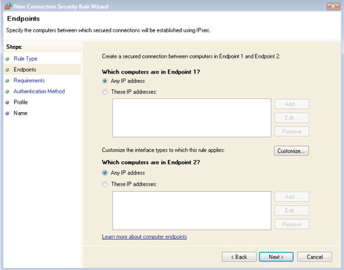
To specify individual devices to which this rule should apply, click Add. You’ll be taken to the IP Address screen shown in Figure 6.30, where you’ll be able to specify one or more single IP addresses, a range of IP addresses, or one of the predefined sets of devices discussed in the “Configuring an Authentication Exemption Rule” section. You can also select Customize to specify the type of interface to which the rule should apply: LAN, remote access, or wireless. The rule can be applied to one, two, or all three of these interface types; it will be applied to all interface types by default.
Click Next once you have specified the endpoints to which this rule should apply. You will then be prompted to select one of the following three authentication requirements for the new isolation rule:
■ Request authentication for inbound and outbound connections
■ Require authentication for inbound connections and request authentication for outbound connections
■ Require authentication for inbound and outbound connections
Click Next once you’ve made your selection. You can then choose from one of the following three authentication methods:
■ Computer Certificate If you select this option, you will be prompted to enter the name of a CA on your network. You will also have the option to accept only NAP health certificates.
■ Preshared key As we discussed earlier, this is a low-security authentication method that Microsoft does not recommend; it is included only for backward compatibility and to ensure compliance with the IPSec RFC standards.
■ Advanced If you select this option, you will be prompted to configure a custom authentication method as described earlier, in the “Authentication Method” section.
When you’ve selected the authentication method that this rule should use, click Next. You will then be prompted to select which Windows Firewall profile will apply this rule: Domain, Public, and/or Private. You can configure this rule to be enforced under one, two, three, or none of the Windows Firewall profiles. Click Next to continue. You’ll be prompted to enter a name and an optional description for this rule. Click Finish when you’re done. You’ll be returned to the main MMC snap-in window, where you will see the newly created rule listed in the main window. From here, you can right-click on the rule to disable or delete it, or you can select Properties to modify any of the settings that you configured in the wizard.
Configuring a Tunnel Rule
To create a tunnel connection security rule, most commonly in the case of a site-to-site VPN, select Tunnel from the screen shown in Figure 6.29 and then click Next. You’ll be presented with the screen in Figure 6.32.
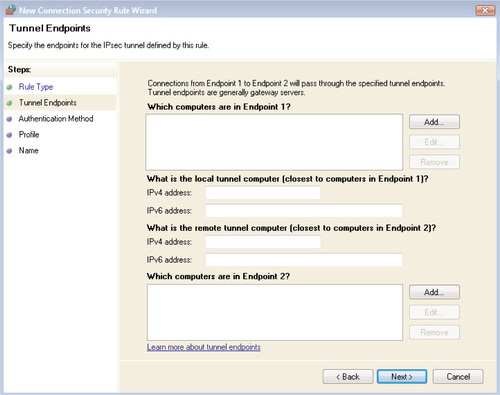
Use the Add button to specify the computers that are being protected by each tunnel node; you’ll be taken to the IP Address screen shown in Figure 6.30, where you’ll be able to specify one or more single IP addresses, a range of IP addresses, or one of the predefined sets of devices discussed in the “Configuring an Authentication Exemption Rule” section. Then specify the IP address of the tunnel gateway node for each endpoint; you can specify the IPv4 and IPv6 addresses if they are available.
Click Next once you’ve specified the IP addresses and tunnel endpoints for each end of the connection. You can then choose from one of the following three authentication methods:
■ Computer Certificate If you select this option, you will be prompted to enter the name of a CA on your network. You will also have the option to accept only NAP health certificates.
■ Preshared key As we discussed earlier, this is a low-security authentication method that Microsoft does not recommend; it is included only for backward compatibility and to ensure compliance with the IPSec RFC standards.
■ Advanced If you select this option, you will be prompted to configure a custom authentication method as described earlier, in the “Authentication Method” section.
When you’ve selected the authentication method that this rule should use, click Next. You will then be prompted to select which Windows Firewall profile will apply this rule: Domain, Public, and/or Private. You can configure this rule to be enforced under one, two, three, or none of the Windows Firewall profiles. Click Next to continue. You’ll be prompted to enter a name and an optional description for this rule. Click Finish when you’re done. You’ll be returned to the main MMC snap-in window, where you will see the newly created rule listed in the main window. From here, you can right-click on the rule to disable or delete it, or you can select Properties to modify any of the settings that you configured in the wizard.
Creating a Custom Connection Security Rule
If none of the preconfigured rule definitions fits your needs, you can create a custom rule by selecting Custom from the screen shown in Figure 6.29 and clicking Next. You’ll be taken to the screen shown in Figure 6.31, where you’ll need to specify which IP address or addresses are contained in Endpoint 1 and Endpoint 2. To specify individual devices to which this rule should apply, click Add. You’ll be taken to the IP Address screen shown in Figure 6.30, where you’ll be able to specify one or more single IP addresses, a range of IP addresses, or one of the predefined sets of devices discussed in the “Configuring an Authentication Exemption Rule” section. You can also select Customize to specify the type of interface to which the rule should apply: LAN, remote access, or wireless. The rule can be applied to one, two, or all three of these interface types; it will be applied to all interface types by default.
Click Next once you have specified the endpoints to which this rule should apply. You will then be prompted to select one of the following three authentication requirements for the new isolation rule:
■ Request authentication for inbound and outbound connections
■ Require authentication for inbound connections and request authentication for outbound connections
■ Do not authenticate
Click Next once you’ve made your selection. You will then be prompted to select the authentication method that this rule should use. Choose among the following:
■ Computer and User (Kerberos V5).
■ Computer (Kerberos V5).
■ Computer Certificate. If you select this option, you will be prompted to enter the name of a CA on your network. You will also have the option to accept only NAP health certificates.
■ Advanced. If you select this option, you will be prompted to configure a custom authentication method as described earlier, in the “Authentication Method” section.
Once you have made your choice, click Next. You will then be prompted to select which Windows Firewall profile will apply this rule: Domain, Public, and/or Private. You can configure this rule to be enforced under one, two, three, or none of the Windows Firewall profiles.
Click Next to continue. You’ll be prompted to enter a name and an optional description for this rule. Click Finish when you’re done. You’ll be returned to the main MMC snap-in window, where you will see the newly created rule listed in the main window. From here, you can right-click on the rule to disable or delete it, or you can select Properties to modify any of the settings that you configured in the wizard.
Creating Firewall Rules
In addition to configuring connection security rules, you can use the Windows Firewall with Advanced Security MMC snap-in to exert far more granular control over inbound traffic rules than is available within the Control Panel applet. You can view any existing inbound rules by clicking on Inbound Rules from the main screen of the MMC snap-in; likewise, you can view any existing outbound rules by clicking on Outbound Rules. If you right-click on either of these nodes, you can view only a subset of these rules, filtered in one of three ways:
■ Filter by Profile will show only those rules that have been configured for the Domain, Private, or Public profile. Selecting Show All will remove any filters.
■ Filter by State will show only those rules that are currently enabled or disabled. Again, selecting Show All will remove any filters and display all defined rules.
■ Filter by Group will only show rules that are associated with a particular predefined rule set, such as BITS Peercaching or Connect to a Network Projector, or you can display only those rules that are not associated with a group. Selecting Show All will remove any filters.
To create a new rule, right-click on Inbound Rules and select New Rule. You’ll see the screen shown in Figure 6.33. You can create one of the following types of inbound rules; we will discuss each one in turn:
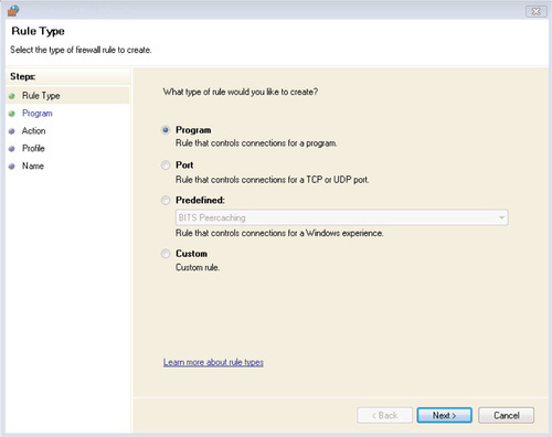
■ Program creates a rule that is associated with a particular executable file, similar to the Add Program option on the Exceptions tab of the Windows Firewall Control Panel applet.
■ Port creates a rule associated with a network port, similar to the Add Port option in the Windows Firewall Control Panel applet.
■ Predefined creates a rule associated with one of the services that have been predefined within the Windows Vista firewall, such as BITS Peercaching or Network Discovery.
■ Custom creates a custom rule when none of the preconfigured choices is appropriate for your needs.
Creating a Program Firewall Rule
To configure a firewall rule associated with a particular application, select Program from the screen shown in Figure 6.33 and click Next. You can create a rule that applies to one of the following:
■ All programs affects all programs that are installed on the local computer.
■ This program path allows you to click Browse to select an individual .exe file.
Click Next when you have made your selection. You’ll be prompted to select one of the following Actions that should be taken when an executable is found that matches this rule:
■ Allow the connection if it is secure. If you select this option, you can select one or both of the following additional options:
Require the connections to be encrypted.
Override block rules. This enables the Authenticated IPSec Bypass option that will allow IPSec-authenticated users and computers to bypass inbound firewall rules. This option is available only when configuring an inbound rule.
■ Block the connection.
Click Next once you have chosen the appropriate action for this rule to take. If you select Allow the connection if it is secure, you will be taken to the screen shown in Figure 6.34. To restrict connections to only specific computers, place a checkmark next to Only allow connections from these computers; click Add to add one or more Active Directory computer accounts to the firewall rule. To restrict inbound connections to specific Active Directory user objects, place a checkmark next to Only allow connections from these users; click Add to specify one or more Active Directory user or group objects. Both of these checkboxes are optional; you do not need to restrict the rule to specific users or computers if you do not want to do so.
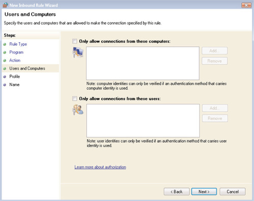
If you were taken to the Users and Computers screen shown in Figure 6.34, click Next once you have made the appropriate selections. Once you have made your choice, click Next. You will then be prompted to select which Windows Firewall profile will apply this rule: Domain, Public, and/or Private. You can configure this rule to be enforced under one, two, three, or none of the Windows Firewall profiles.
Click Next to continue. You’ll be prompted to enter a name and an optional description for this rule. Click Finish when you’re done. You’ll be returned to the main MMC snap-in window, where you will see the newly created rule listed in the main window. From here, you can right-click on the rule to disable or delete it, or you can select Properties to modify any of the settings that you configured in the wizard.
Creating a Port Firewall Rule
To configure a firewall rule associated with a particular network port, select Port from the screen shown in Figure 6.33 and click Next. You’ll need to specify the following information:
■ Is the exception being created for a TCP port or a UDP port?
■ Does the exception correspond to all port numbers (whether TCP or UDP), or one or more specific local ports? You can enter an individual port number, or you can separate multiple port numbers with commas. However, ports within an individual rule must be all TCP or all UDP. You cannot create a single firewall rule that corresponds to TCP port 138 and UDP port 138; this will require that two separate rules be created.
Click Next once you’ve entered the port information. The remaining steps in the wizard are identical to creating a program firewall rule:
■ Specify the action to be taken: Allow, Block, Secure, Secure and require encryption, or Secure and override block rules.
■ If you are creating a Secure rule, optionally restrict connections to specific user or computer objects for inbound connections, or to specific computer objects for outbound connections.
■ Specify which profile(s) the rule should apply to.
■ Provide a name and a description for the rule.
You’ll be returned to the main MMC snap-in window, where you will see the newly created rule listed in the main window. From here, you can right-click on the rule to disable or delete it, or you can select Properties to modify any of the settings that you configured in the wizard.
Configuring a Predefined Firewall Rule
To modify the rules associated with one of the predefined Windows Vista exceptions, choose Predefined from the screen shown in Figure 6.33. (You should select this option with care, because you will be overwriting the predefined firewall rules that were installed with Windows Vista.) Select the exception that you want to modify and click Next. For this example, we have selected the Connect to a Network Projector exception. You will see the screen shown in Figure 6.35.
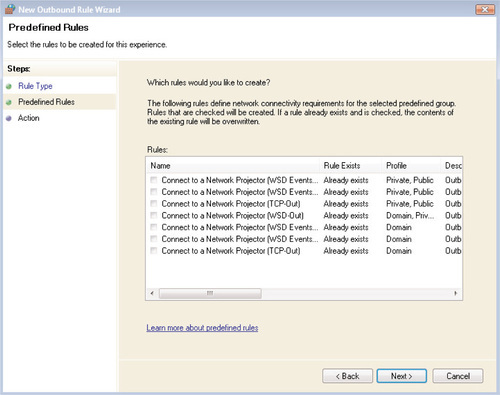
Place a checkmark next to as many individual rules as you want to modify, and then click Next. Again, select this option with care, because you will be overwriting the existing rule set. You’ll be prompted to select one of the following actions that should be taken when an executable is found that matches this rule:
■ Allow the connection if it is secure. If you select this option, you can select one or both of the following additional options:
Require the connections to be encrypted.
Override block rules. This enables the Authenticated IPSec Bypass option that will allow IPSec-authenticated users and computers to bypass inbound firewall rules. This option is available only when configuring an inbound rule.
■ Block the connection.
If you select Allow the connection if it is secure, you will be returned to the screen shown in Figure 6.34 to specify which user and/or computer accounts to allow connections to or from. Otherwise, your only option will be to select Finish to save your changes.
Creating a Custom Firewall Rule
Configuring a custom firewall rule allows you the greatest amount of flexibility in configuring the Windows Firewall. To begin configuring a custom rule, select Custom from the screen shown in Figure 6.33 and then click Next.
Your first configuration step will be to define the program to which this exception applies. Select one of the following:
■ All programs This rule will apply to all connections to the local computer that match any other properties defined within the custom rule.
■ This program path Select this option and browse to the specific executable file to which the custom exception refers.
Also on this screen, you’ll need to configure which services and processes this exception will refer to. Click Customize to select one of the following options:
■ Apply to all programs and services.
■ Apply to services only.
■ Apply to this service. This option allows you to select a specific Windows service.
■ Apply to service with this service shortname. This option allows you to specify the shortname of the service in question, such as eventlog or w3svc.
Click Next once you’ve defined the program to which this exception applies. You’ll be taken to the screen shown in Figure 6.36, which will allow you to specify the following information about any specific port to which this exception refers:
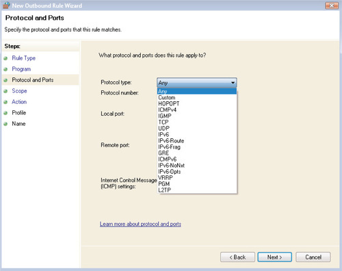
■ Protocol type Most commonly TCP, UDP, or ICMPv4, but other options such as IGMP and GRE are available.
■ Protocol number This field is automatically populated based on your choice of protocol type.
■ Local port You can choose Any port or specify one or more specific ports from which this traffic will originate, with multiple port numbers separated by commas. All ports that you specify must be of the same protocol type:TCP 135 and TCP 139, for example, but not TCP 21 and UDP 22.
■ Remote port Similar to the local port, you can choose Any port or specify one or more ports of the same protocol type.
■ Internet Control Message Protocol (ICMP) settings If you select ICMPv4 or ICMPv6 as the protocol type, you can allow this rule to apply to all ICMP traffic, or you can specify one or more of the following ICMP message types.
For ICMPv6:
2. Packet Too Big
3. Time Exceeded
4. Parameter Problem
5. Echo Request
6. Multicast Listener Query
7. Multicast Listener Report
8. Multicast Listener Done
9. Router Solicitation
10. Router Advertisement
11. Neighbor Discovery Solicitation
12. Neighbor Discovery Advertisement
13. Redirect
14. Multicast Listener Report v2
And for ICMPv4:
1. Packet Too Big
2. Destination Unreachable
3. Source Quench
4. Redirect
5. Echo Request
6. Router Advertisement
7. Router Solicitation
8. Time Exceeded
9. Parameter Problem
10. Timestamp Request
11. Address Mask Request
Once you’ve defined any relevant port and protocol settings, click Next. You’ll then need to define both the local and remote IP addresses to which this exception refers. For both the local and remote addresses, you can select either Any IP Address or These IP Addresses. To specify the IP addresses to which this rule should apply, click These IP Addresses and then click Add. You’ll be taken to the IP Address screen shown in Figure 6.30, where you’ll be able to specify one or more single IP addresses, a range of IP addresses, or one of the predefined sets of devices discussed in the “Configuring an Authentication Exemption Rule” section. You can also select Customize to specify the type of interface to which the rule should apply: LAN, remote access, or wireless. The rule can be applied to one, two, or all three of these interface types; it will be applied to all interface types by default.
Click Next once you have specified the local and remote IP addresses to which this rule should apply. You’ll be prompted to select one of the following actions that should be taken when a packet is found that matches this custom rule:
■ Allow the connection if it is secure. If you select this option, you can select one or both of the following additional options:
Require the connections to be encrypted.
Override block rules. This enables the Authenticated IPSec Bypass option that will allow IPSec-authenticated users and computers to bypass inbound firewall rules. This option is available only when configuring an inbound rule.
■ Block the connection.
If you select Allow the connection if it is secure, you will be returned to the screen shown in Figure 6.34 to specify which user and/or computer accounts to allow connections to or from. Otherwise, your only option will be to select Finish to save your changes.
If you were taken to the Users and Computers screen shown in Figure 6.34, click Next once you have made the appropriate selections. Once you have made your choice, click Next. You will then be prompted to select which Windows Firewall profile will apply this rule: Domain, Public, and/or Private. You can configure this rule to be enforced under one, two, three, or none of the Windows Firewall profiles.
Click Next to continue. You’ll be prompted to enter a name and an optional description for this rule. Click Finish when you’re done. You’ll be returned to the main MMC snap-in window, where you will see the newly created rule listed in the main window. From here, you can right-click on the rule to disable or delete it, or you can select Properties to modify any of the settings that you configured in the wizard.
Monitoring the Windows Firewall
Using the Windows Firewall with Advanced Security MMC snap-in, administrators now have access to real-time firewall configuration information that can be invaluable in troubleshooting connectivity issues on Vista workstations. Simply open the MMC snap-in and select Monitoring in the left-hand pane, as shown in Figure 6.37.
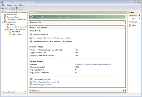
From the main Monitoring screen shown in Figure 6.37, you will see an at-a-glance summary of your current firewall settings, describing the overall state of the firewall, which profile is active, as well as notification and logging settings. You also have the ability to drill down to a detailed view of any of the following:
■ Active security connection rules
■ Active IPSec SAs
In Figure 6.38, you can see the information that is displayed when you drill down to the Firewall node: which firewall rules are currently active, as well as specific details on each rule, including the name of the rule, the action associated with that rule (allow, secure, block), and whether it is an inbound or outbound firewall rule.
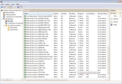
Summary
As you’ve seen throughout this chapter, Windows Vista has made numerous improvements in the way that it handles network communications with other computers on a local area network or on the Internet. These changes have been designed to enhance both the security and usability of the new Microsoft operating system for both end users and corporate administrators.
Windows Vista is the first Microsoft operating system release that has enabled full support and interoperability for the IPv6 standard as a default part of the operating system. IPv6 can be configured through the Vista graphical user interface, or you can use the familiar netsh command-line utility. Vista has enabled full IPv6 compliance while still allowing Vista computers to communicate using the current IPv4 implementation that is still the de facto standard on the Internet and for most corporate networks.
In addition to IPv6 support, Vista offers a greatly improved graphical user interface for configuring and troubleshooting wired and wireless network connections. The new Network and Sharing Center includes options for displaying a graphical view of your network infrastructure using the Network Map, as well as providing a simple way to configure a new network connection as either a public or private network with the security settings that are appropriate to each.
In the second half of this chapter we spent a great deal of time examining the Windows Firewall, which has been greatly improved within Windows Vista. The new Windows Firewall with Advanced Security has been more fully integrated with the Windows implementation of IPSec, and it now allows you to control both inbound and outbound connections to and from a Windows Vista computer. These settings can be configured using the Vista graphical user interface or the netsh command-line tool. You can even configure consistent settings across a small or large network by using Group Policy Objects.
Solutions Fast Track
Not Your Father’s TCP/IP Stack
☑ IPv6 was designed to address numerous shortcomings in the IPv4 standard, including a lack of built-in security measures and an inefficient addressing system.
☑ Windows Vista is the first Microsoft OS to provide IPv6 support out of the box.
☑ You can configure IPv6 from the Windows Vista Control Panel, as well as from the command line using the netsh tool.
Using the Network and Sharing Center
☑ Windows Vista introduces the concept of network locations, allowing you to configure different settings for public, private, and office networks.
☑ Windows Vista introduces a new protocol for Network Discovery, which uses the WSDAPI framework as a secure channel when communicating between a device and a client, as well as the Simple Service Discovery Protocol.
☑ You can use Public Folder Sharing to allow for easier shared file access between multiple users of a single computer, as well as users across a SOHO or other peer-to-peer network.
Using the Network Map
☑ The new Network Map provides a graphical view of your local computer’s relative position on the network, as well as indicating any networked computers that have been configured for Network Discovery and/or File and Printer Sharing.
☑ The Network Map can be used for network troubleshooting: If a particular network segment becomes disconnected, it will be displayed on the Network Map with a red X over the segment.
☑ The Network and Sharing Center also offers options to diagnose and repair issues with network connectivity.
Working with the Windows Firewall
☑ The Windows Firewall with Advanced Security is a stateful, host-based firewall that can be configured to allow or disallow traffic that is generated by an executable file or by one or more TCP or UDP ports.
☑ Windows Vista offers numerous preconfigured Windows Firewall exceptions to allow traffic for common Vista networking scenarios, such as using BITS Peercaching or connecting to a network projector.
☑ Connection security rules can be used to define how devices should authenticate with one another before communication can take place.
Frequently Asked Questions
The following Frequently Asked Questions, answered by the authors of this book, are designed to both measure your understanding of the concepts presented in this chapter and to assist you with real-life implementation of these concepts. To have your questions about this chapter answered by the author, browse to www.syngress.com/solutions and click on the “Ask the Author” form.
Q: What does the Windows Firewall do if it is configured with two conflicting rules: one that disallows a particular type of traffic and one that allows it?
A: Block rules will be given precedence over allow rules; if Windows Vista encounters a firewall rule that blocks a particular type of traffic, that traffic will be blocked even if other allow rules are in place.
Q: I would like to configure Windows Firewall settings across my entire organization. Does Vista allow for this?
A: If you are working in an Active Directory environment, you can use Group Policy to apply consistent settings across an entire organization for numerous Windows Vista features, including Internet Explorer, Windows Defender, and the Windows Firewall.
Q: You’ve mentioned Network Access Protection several times in this chapter. What is it?
A: Network Access Protection, or NAP, is a new service that will be offered in the new version of Windows Server currently codenamed Longhorn. NAP is a policy enforcement mechanism that can monitor the health of your Windows Vista and Windows XP SP2 workstations and limit their network access if their health falls out of compliance with your corporate standards. For example, if a traveling user’s laptop has become infected with a virus or worm, NAP can quarantine the network connection when the user attempts to connect to the corporate network so that the virus does not spread to other computers on the corporate network.
Q: I have numerous Windows XP computers on my network that are not being displayed in the Network Map. Is the Network Map available only for Vista computers?
A: Not at all; however, you need to install an update on the Windows XP computers so that they can be displayed on the Network Map. Check out Knowledge Base article 922120 on the Microsoft Web site for more information.