
Chapter 1
Next Generation Wireless Networks
Wireless networks nowadays are part of our everyday life, as witnessed by several features: the number of cell (mobile) phone subscriptions reached 4.6 billion in February 2010 (News 2010) and is expected to reach 6 billion (corresponding to about 72% of current world population) by the middle of 2012; short-range radio technologies such as WiFi (Alliance 2011a) and Bluetooth (Bluetooth-SIG 2011) are widespread; innovative technologies based on short-range wireless communication and miniaturized sensor devices have recently been standardized (Alliance 2011b), or are in the final steps of standardization; radio frequency IDs (RFIDs) are becoming a prominent technology in logistics and object tracking; short-range radio technology is being developed and will shortly be deployed onboard vehicles to improve safety conditions on the road and to enable innovative intelligent transportation systems; and so on.
A major outcome of intensive research in both industry and academia in recent years has been the consolidation of a wealth of short-range, inexpensive radio technologies, which promoted, and will promote even further in forthcoming years, the definition of novel network architectures such as ad hoc networks, mesh networks, wireless sensor networks, vehicular networks, and opportunistic networks. It is widely believed that these classes of networks, which we call next generation wireless networks, will enable the vision of “ubiquitous computing” to become a reality in the next few years.
Clarification about the term next generation wireless network as used throughout this book is in order. In a search on Google for “next generation wireless network,” top hits mostly refer to evolutions of the cellular technology collectively named 4G, including technologies such as LTE (Long-Term Evolution), LTE Advanced, etc. These technologies are essentially aimed at improving capacity and quality of service (QoS) in cellular networks, especially that which concerns data services, which are expected to play an increasing role in coming years. For instance, LTE Advanced is expected to provide maximal data rates of 1 Gbps in downlink and of 500 Mbps in uplink, compared to data rates of 84 Mbps and 22 Mbps of current high-speed packet access (HSPA+) technology. However, the above improvements are mostly obtained through advancements in the physical and medium access layer of the network protocol stack, for example, through extensive use of multi-antenna systems, while the overall architecture of the cellular network is mostly unchanged. Thus, forthcoming 4G networks can be considered as an evolution of the well-established cellular network concept.
On the other hand, the class of networks (ad hoc networks, mesh networks, wireless sensor networks, vehicular networks, and opportunistic networks) that we collectively call next generation wireless networks are characterized by very different features compared to cellular networks:
- Cellular networks rely heavily on a wired, very expensive communication infrastructure—the network of cellular base stations—to perform communication; on the contrary, next generation wireless networks are characterized by a lightweight—or even absent—infrastructure.
- Cellular networks are based on the use of relatively long wireless links, with typical communication ranges in the order of up to a few kilometers; on the contrary, next generation wireless networks use short-range—in the order of a few tenths of meters, or hundreds of meters at most—wireless links.
- Cellular networks rely heavily on the presence of several centralization points, where servers are used for optimizing resource allocation and coordinate radio channel access between the different users in a cell and in adjacent cells; on the contrary, in next generation wireless networks, centralization points are typically lacking, and most network functionalities must be realized in a fully distributed, self-coordinated environment.
- Cellular networks are single-hop wireless networks, since a mobile terminal directly communicates with a base station in the vicinity; on the contrary, next generation wireless networks typically make extensive use of multi-hop communications to compensate for the short radio range and increase coverage.
It is then evident that the class of emerging short-range wireless networks mentioned above displays striking differences with respect to traditional cellular networks, and that the design and realization of a network of this class entails defining brand-new network architectures and networking solutions spanning the entire network protocol stack. This explains our choice of naming the emergent class of short-range, multi-hop, decentralized wireless networks “next generation wireless networks.” Unless stated otherwise, in the remainder of this book we will use the term next generation wireless network exclusively to refer to a member of the class of short-range, multi-hop, decentralized wireless networks. The main differences between cellular and next generation wireless networks are summarized in Table 1.1.
Table 1.1 Differences between cellular and next generation wireless networks
| Cellular network | Next generation wireless network | |
| Infrastructure | Yes | No, lightweight |
| Radio range | ≤2 km | ≤300 m |
| Centralization points | Yes | Mostly no |
| Type of communication | Single-hop | Multi-hop |
| Radio channel access | Coordinated | Mostly uncoordinated |
In the remainder of this chapter, we will briefly describe different types of next generation wireless networks and relevant application scenarios, as well as the several challenges that the designers of such networks will face.
1.1 WLAN and Mesh Networks
A wireless local area network (WLAN) is a network connecting two or more devices (called stations in WLAN terminology) in a relatively small area (e.g., a building, a university campus, etc.), and usually providing a connection to the Internet through one or more access points (APs). A distinguishing feature of WLANs with respect to traditional, wired LANs is that station-to-station and station-to-AP connections exploit wireless technology.
A typical WLAN architecture is reported in Figure 1.1: one or more APs, which are directly connected to the Internet through a wired connection (typically, an Ethernet link), set up and operate wireless links with one or more stations within their coverage area. Wireless connections are typically realized through the establishment of IEEE 802.11 links. The family of IEEE 802.11 protocols (IEEE 2011a) is at the basis of WiFi technology, and allows point-to-point links to be established between different stations, and between stations and APs, at a data rate as high as 600 Mbps (forthcoming IEEE 802.11n).
Figure 1.1 A typical WLAN architecture.
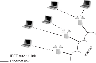
Two factors have contributed to the success of WLANs: the increasing popularity of laptop computers and powerful handheld devices such as PDAs and smart phones on the one hand, and the maturing of WiFi into a very affordable, short-range wireless technology on the other hand. Due to these factors, WLANs are now widely used to provide Internet connectivity in corporate buildings, university campuses, coffee shops, bookstores, airports, shopping malls, etc. With their high data rates and affordable prices, small-scale WLANs have de facto become the standard way of connecting to the Internet, even in the home.
A major problem facing WLAN designers is radio coverage. In fact, the typical communication range of an IEEE 802.11 radio is up to 100 m (usually much less in indoor environments), implying that many APs must be deployed to cover a relatively large area. For instance, several hundred APs are typically needed to provide indoor and outdoor Internet connectivity to a medium-sized university campus. Considering that in the standard WLAN architecture wireless APs need a wired connection to an Internet gateway, the logistics and wiring cost of setting up a relatively large and dispersed WLAN might be problematic. To overcome this, the IEEE 802.11 working group has recently drafted an amendment to the standard, named IEEE 802.11s, that allows the creation of a WLAN mesh network.
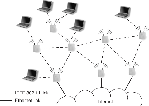
The main building block of a WLAN mesh network, as reported in Figure 1.2, is a device called a mesh station, which has the ability to establish point-to-point wireless links with other mesh stations, thus realizing a multi-hop, mesh network architecture between the mesh stations composing the WLAN. A mesh station, also known as a mesh router in the mesh networking research literature, can incorporate additional functionality, namely: (i) AP functionality to provide wireless access to WLAN stations; and (ii) Internet gateway functionality, if the mesh station has a wired connection to the Internet. It is important to observe that, in the WLAN mesh network concept, AP and gateway functionality are optional, and are in general provided only by a subset of the mesh stations. For instance, a mesh station might be deployed with the sole purpose of acting as a bridge between different parts of the WLAN, in which case neither functionality (i) nor (ii) are provided.
Figure 1.2 A typical WLAN mesh network architecture.
WLAN mesh networks have several potential advantages with respect to traditional WLANs:
From the point of view of a network designer, the price to pay for the above advantages is the need to design additional networking solutions with respect to those required in a typical WLAN situation. In particular, since multi-hop wireless communications are heavily exploited in WLAN mesh networks, suitable protocols for routing packets from stations to an Internet gateway through the mesh stations should be designed. Furthermore, resource and bandwidth allocation strategies should be implemented to allow effective and fair sharing of the available bandwidth between the mesh stations and, ultimately, between the stations registered with the APs. Finally, from a technological point of view a major challenge is to increase the capacity of the set of wireless links between mesh stations as much as possible, as this part of the network is likely to become a bottleneck if several stations are registered with the APs.
The notion of mesh network is not exclusive to the WLAN concept. In fact, mesh networking solutions are currently being considered and standardized also for other types of networks, such as within the realm of wireless metropolitan area networks—see WiMax Mesh Mode of operation (WiMax-Forum 2011). For a more detailed description of WLAN and mesh networks, the interested reader is referred to Chapter 8 of this book and references therein.
1.2 Ad Hoc Networks
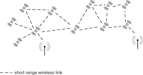
An ad hoc network is an infrastructure-less, wireless multi-hop network composed of a set of wireless point-to-point links between a set of nodes. The architecture of a typical ad hoc network is shown in Figure 1.3. The term MANET (Mobile Ad hoc NETwork) is commonly used to refer to an ad hoc network whose nodes are mobile.
Figure 1.3 A typical ad hoc network architecture.
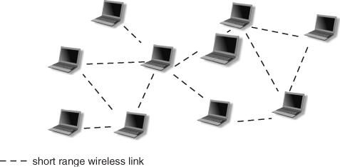
Differently from WLANs and mesh networks, no infrastructure or centralization point is available to coordinate network functionality and radio resource allocation, so nodes in an ad hoc network must be able to self-organize, set up, and maintain a suitable set of wireless links, as well as to implement all necessary networking protocols in a fully distributed way. Also, the typical traffic pattern in ad hoc network is quite different with respect to those in WLAN and mesh networks: while in the latter types of networks traffic is typically directed to or coming from Internet gateways, ad hoc networks are mostly used to exchange data within the network itself, so the typical traffic pattern is peer-to-peer.
The prominent wireless technologies used to set up the wireless links in an ad hoc network are IEEE 802.11 and Bluetooth. Both technologies, in fact, allow the creation and operation of wireless links in a point-to-point fashion: in IEEE 802.11, the ad hoc mode can be used to set up point-to-point links without the assistance of an AP; in Bluetooth, piconets of up to seven nodes can be formed, with one of the nodes acting as the coordinator; piconets can then be joined through nodes acting as bridges to form larger so-called scatternets. The data rates achievable on the wireless links are those typical of the respective technology, that is, up to 600 Mbps with IEEE 802.11, and up to 24 Mbps with Bluetooth (version 3.0).
Ad hoc networks were originally proposed in military applications—to provide communication between members of a platoon on the battlefield. Another prominent application scenario of ad hoc networks is disaster relief, where this flexible, quick-to-deploy network can be used to provide communication between members of a rescue squad, firefighters, police officers, etc., in case the pre-existing communication infrastructure is no longer working.
Despite the concept of ad hoc network being introduced more than 30 years ago, applications based on the ad hoc networking paradigm outside the military scope are almost completely lacking to date. This is due to the severe challenges that must be faced by an effective ad hoc network design, which can be summarized as follows:
The above-mentioned severe challenges have limited the widespread application of the general ad hoc network concept. However, this networking concept still plays a major role in next generation wireless networks, as it is the basis of more specialized classes of short-range wireless networks, such as vehicular networks, wireless sensor networks, and opportunistic networks, which will be described in the remainder of this chapter.
1.3 Vehicular Networks
Vehicular networks are short-range wireless networks where links are established between nearby vehicles, or between a vehicle and a so-called road side unit (RSU). RSUs are typically constituted of radio devices installed on top of road side poles, which are typically part of a pre-existing road infrastructure (traffic lights, street lamps, etc.).
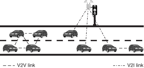
The architecture of a typical vehicular network is shown in Figure 1.4. As seen from the figure, vehicle-to-vehicle (V2V) and vehicle-to-infrastructure (V2I) links (i.e., links between a vehicle and a RSU) coexist in a vehicular network, with the purpose of forming a highly dynamic, mobile network allowing exchange of messages between vehicles, and possibly between vehicles and external networks (e.g., the Internet), which can be accessed through the RSU. From an architectural point of view, vehicular networks share features with ad hoc and opportunistic networks. In fact, the part of the network formed of V2V links between vehicles can be considered as a special type of MANET, which is named a vehicular ad hoc network, or VANET, in the corresponding literature. On the other hand, if a message has to be delivered to an external network (e.g., the report of a measured travel time), a vehicle often needs to store and carry the message for a relatively long time, till a communication opportunity arises when a RSU comes into reach. Thus, the store, carry, and forward communication paradigm typical of opportunistic networks (see Section 1.5) is exploited.
Figure 1.4 A typical vehicular network architecture.
Vehicular networks are attracting increasing interest and investment in research as well as in the automotive industry, and receiving massive funding from governments and various agencies. In fact, they are considered as a prominent means of improving road safety conditions and traffic efficiency in forthcoming years:
- Vehicular networks for improving road safety conditions. Direct message exchange between vehicles can be used to let active safety applications running onboard vehicles acquire an up-to-date view of the traffic situation surrounding the vehicle, which is typically achieved through exchange of status messages (i.e., messages reporting information such as vehicle speed, position, direction, and so on) between vehicles. In turn, up-to-date situation awareness enables a suitably designed active safety application to identify early possible hazards and dangerous conditions, which will be immediately communicated to the driver so that she/he can take adequate countermeasures. The primary design goal of active safety applications based on vehicular networks is extending situation awareness beyond human eyes, so that a driver can be warned of a potentially dangerous situation well before her/his eyes can see the situation. Considering that reducing a driver's reaction time of a fraction of a second would result in avoiding the majority of accidents, a large fraction of road accidents can potentially be avoided through vehicular networking technologies.
- Vehicular networks for improving traffic efficiency. Message exchange between vehicles, and between vehicles and RSUs, can be exploited to quickly inform vehicles about changes of traffic status (e.g., traffic build-up due to an accident). In principle, real-time traffic monitoring and smart navigation systems (i.e., systems that dynamically change the suggested travel path based on real-time traffic information) can lead to considerable reductions in travel time and to increased traffic efficiency in general. Other types of vehicular network applications aimed at improving traffic efficiency are being designed, such as lane merging assistance, intersection assistance, and so on.
Besides road safety and traffic efficiency applications, other classes of applications are being investigated for vehicular networks, such as peer-to-peer file sharing between neighboring vehicles, chat, localized advertisements, VoIP, etc. However, while for safety/traffic-related applications there is a strong push from both governmental agencies and the automotive industry, “entertainment”-related applications are currently seen as a less important class of applications for vehicular networks. We envision, though, that once the vehicular networking technology has been settled, several entertainment-related applications will be developed and will rapidly become widespread.
Although in principle different radio technologies could be used for V2V and V2I communications, in order to reduce cost and design complexity a single radio technology (and, typically, also a single radio device onboard vehicles) is used for both V2V and V2I communications. The radio technology which is being promoted for vehicular communications is a specialization of the well-known WiFi standard for vehicular environments. More specifically, an amendment to the IEEE 802.11 standard, called IEEE 802.11p (IEEE 2011b), is currently in an advanced status of definition. The main purpose of IEEE 802.11p is to combat severe radio propagation issues arising in vehicular environments, mostly related to a very strong Doppler effect due to high vehicular velocities. Another goal of IEEE 802.11p is to reduce the signaling overhead needed to set up a V2V or V2I link, given the highly dynamic nature of vehicular networks. The current IEEE 802.11p draft allows data rates as high as 54 Mbps on the radio link, although much lower data rates (3 or 6 Mbps) are mandated for active safety application. For a more detailed description of IEEE 802.11p, the reader is referred to Chapter 11.
Several challenges are faced by the vehicular network designer in order to turn the above vision of improved road safety conditions and traffic efficiency into reality. These challenges encompasses both communication and networking aspects. From the communication point of view, a major challenge is to design a radio technology that allows low-delay, reliable communications in a highly dynamic, mobile, and possibly congested radio environment. Low delays and highly reliable communications are prerequisites for an effective active safety application design. From a networking perspective, challenges are related to the design of innovative solutions at the different layers of the network architecture, which are needed to support the above-mentioned classes of vehicular network applications. For instance, concerning the network layer, several routing primitives should co-exist in a vehicular network, such as traditional, IP-based routing (e.g., to access the Internet through a RSU), geo-routing (e.g., to reach vehicles in a specific area to warn them of a change in traffic conditions), geographically scoped broadcast, etc. The above should be achieved in a highly dynamic, mobile environment, where frequent disconnections typically occur, making the design challenge even harder. For a more detailed description of the communication and networking challenges in vehicular networks, the interested reader is referred to Chapter 11.
1.4 Wireless Sensor Networks
Wireless sensor networks (WSNs) are short-range radio networks composed of radio-equipped sensor nodes and a few gathering points, named base stations or sink nodes in wireless sensor network terminology. A typical wireless sensor network architecture is displayed in Figure 1.5. Similar to vehicular networks, WSNs can be considered as a specific class of ad hoc network, where network nodes are mostly fixed. Another distinguishing feature of WSNs is the number of network nodes which, depending on the application scenario, can grow to several thousands.
Figure 1.5 A typical wireless sensor network architecture.
In a typical wireless sensor networking application, a certain environmental parameter (e.g., temperature) is monitored at each sensor node and periodically reported to a base station. The base station is in charge of collecting the data of interest and reporting it to the user(s). If the base station has an Internet connection, remote monitoring of the area of interest is possible. Given the vast geographical area typically covered by a WSN, and the short range of wireless communications, multi-hop communication paths are extensively used to report data to the base stations. Depending on the application and on the nature of the monitored information, data can be aggregated on its route to a base station, achieving significant savings in the total number of messages transmitted within the network.
Wireless sensor networks are increasingly being designed and used to achieve fine-grained monitoring of natural phenomena, to control industrial processes, to improve energy efficiency of buildings, and so on. The major advantage of WSNs with respect to more traditional sensing technologies lies in the fact that sensor nodes are able to communicate with each other and with the base station through wireless links. On the one hand, usage of wireless technology allows considerable reductions in wiring costs, which in some scenarios (e.g., monitoring of industrial processes) represent a large fraction of the total cost of a monitoring system. Also, brand-new monitoring applications can be enabled by usage of wireless technology, such as remote monitoring of wild animals, herds, and so on. On the other hand, usage of wireless links challenges the WSN designer, especially in those application scenarios (e.g., monitoring of industrial processes) where reliability is paramount. Other challenges facing the wireless sensor network designer are related to scalability of the designed solutions, given the large number of nodes comprising a WSN in most application scenarios. Furthermore, energy conservation is also paramount in WSNs, given that wireless sensor nodes are typically battery operated, and replacing batteries is often very difficult. Although energy harvesting technologies (based, for example, on micro solar panels) are increasingly being used in WSNs, efficient use of the available energy is still a major goal—and it will most likely remain so in the future—in the design of wireless sensor network applications.
In terms of technological development, WSNs are in a phase where the communication technology—mostly based on the IEEE 802.15.4 standard (IEEE 2011c) and ZigBee protocol suite (Alliance 2011b)—is relatively mature, and applications of wireless sensor networks are increasingly being developed by both major IT industries and a plethora of small and medium-size enterprises (often spin-offs of major technical universities). For more a detailed description of the state of the art and prospects of wireless sensor networks the interested reader is referred to Chapter 14.
1.5 Opportunistic Networks
Opportunistic networks are a class of MANETs characterized by a very sparse density of nodes, which, coupled with the relatively short range of radio communication, results in a network topology that is disconnected most of the time. A typical opportunistic network architecture is shown in Figure 1.6. A node which is part of an opportunistic network spends most of its time in isolation, without any wireless connection to other nodes. From time to time, a few other nodes of the network might come into reach, giving rise to a communication opportunity, or contact. During a contact, nodes exchange the list of messages in the respective buffers, and might decide to forward some of them to another node. This communication mechanism—called store, carry, and forward—is the basis of opportunistic networking, and enables eventual message reception if and when the destination of a message m comes in contact with a node carrying a copy of m. Clearly, opportunistic network applications must be able to tolerate very large delays in message delivery. For this reason, opportunistic networks are also called delay-tolerant networks in the literature.
Figure 1.6 A typical opportunistic network architecture.
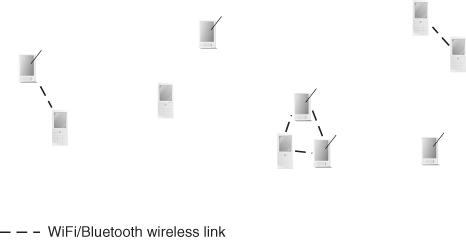
It is important to observe that, since opportunistic networks are disconnected most of the time due to sparse node density, communication opportunities arise typically because of node mobility. In other words, while in other types of next generation wireless networks node mobility is either mostly absent (wireless sensor networks) or perceived as a factor worsening networking performance (in WLANs, mesh networks, vehicular networks, etc.), in opportunistic networks mobility is indeed the only possible communication means: without mobility, network-wide communication would not be possible at all. This is a very distinguishing feature of opportunistic networks with respect to other types of next generation wireless networks, which also explains why so many efforts in the research community have been devoted to understanding and modeling mobility in opportunistic networks (see Part Six of this book).
Although the majority of nodes in an opportunistic network is typically mobile, in some applications a number of fixed nodes are also present in the network. Fixed nodes are typically used either to enable more message-forwarding opportunities within the network, or to provide gateway functionality to external networks. Examples of opportunistic networks where a majority of mobile nodes coexist with a few fixed nodes are instances of vehicular networks, such as DieselNet (see below).
The delay-tolerant network (DTN) concept dates back to the beginning of this century, when Kevin Fall adapted some of the ideas developed around the notion of Interplanetary Internet under investigation at NASA and other agencies to terrestrial networks (Fall 2003). Since then, several applications of the DTN concept have been proposed. Some early examples are ZebraNet (Martonosi et al. 2004), an opportunistic network composed of a small number of radio-equipped zebras living in Sweetwaters Reserve in Kenya, and DieselNet (Group 2007), an opportunistic network composed of 40 public buses in the city of Amherst, Massachusetts.
Recently, a particular class of opportunistic networks called pocket-switched networks is attracting increasing interest in the research community. The notion of a pocket-switched network was first introduced in Hui et al. (2005), where the authors describe an opportunistic network composed of moving individuals carrying a smart phone, PDA, or similar device. The interest in pocket-switched networks stems from the observation that an increasing number of personal mobile communication devices are endowed with several wireless interfaces, allowing not only communication with a cellular network infrastructure, but also direct, peer-to-peer wireless communications. Prominent examples of these wireless interfaces are WiFi and Bluetooth. Hence, very large opportunistic networks composed of individuals moving, say, in a large city can be formed if such wireless interfaces are activated and used to directly exchange messages between mobile devices.
While the communication technology at the base of opportunistic networks in general, and pocket switched networks in particular (mostly WiFi and Bluetooth), is relatively mature, applications for this type of networks are still to be developed, except for a few prototypal examples. The most promising directions seem to be the development of opportunistic networks to provide delay-tolerant Internet connectivity in rural environments, and the extension of social networking applications to mobile environments. In terms of challenges, the major challenge facing the opportunistic network designer is how to reduce message delivery delay as much as possible. In turn, this requires careful optimization of the number of copies of a message circulating in the network, as well as the strategy used to select messages to be forwarded to another node during a contact. With respect to the number of copies of a message circulating in the network, we observe that the higher this number is, the higher the chances for the destination to get in contact with a node carrying a copy of the message; however, a higher number of message copies also entails a larger number of messages circulating in the network, leading to an increased buffer occupation and more chances for a (copy of a) message to be dropped. For more details on the challenges and opportunities of opportunistic networks, the interested reader is referred to Chapter 17.
Alliance W 2011a http://www.wi-fi.org.
Alliance Z 2011b http://www.zigbee.org/.
Bluetooth-SIG 2011 https://www.bluetooth.org/apps/content/.
Fall K 2003 A delay-tolerant network architecture for challenged internets. Proceedings of ACM SIGCOMM, pp. 27–34.
Group PR 2007 http://prisms.cs.umass.edu/dome/umassdieselnet.
Hui P, Chaintreau A, Scott J, Gass R, Crowcroft J and Diot C 2005 Pocket-switched networks and human mobility in conference environments. Proceedings of the ACM Workshop on Delay-Tolerant Networks.
IEEE 2011a http://www.ieee802.org/11/.
IEEE 2011b http://grouper.ieee.org/groups/802/11/Reports/tgp_update.htm.
IEEE 2011c http://www.ieee802.org/15/pub/TG4.html.
Martonosi M, Lyon S, Peh LS, Poor V, Rubenstein D, Sadler C, Juang P, Liu T, Wang Y and Zhang P 2004 http://www.princeton.edu/mrm/zebranet.html.
News C 2010 http://www.cbsnews.com/stories/2010/02/15/business/main6209772.shtml.
Raman B and Chebrolu K 2007 Experiences in using WiFi for rural internet in India. IEEE Communications Magazine 45, 104–110.
WiMax-Forum 2011 http://www.wimaxforum.org/.