, respectively.
from kivy.app import App
from kivy.uix.floatlayout import FloatLayout
from kivy.graphics import Line, Color
from kivy.clock import Clock
import os
import numpy as np
from kivy.lang import Builder
Builder.load_file(
os.path.join(os.path.dirname(os.path.abspath(
__file__)), 'File.kv')
);
#Avoid Form1 of being resizable
from kivy.config import Config
Config.set("graphics","resizable", True)
Config.set('graphics', 'width', '480');
Config.set('graphics', 'height', '680');
#These values are adjusted by the
#function Initialize()
#after Clock.schedule_once has been executed.
#These values are canvas center (XC,YC)
#and width and height (W,H);
XC=0; YC=0; W=0; H=0;
Flag=False;
NUMBER=0;
#============== Polygon structures ===============
#The first entry corresponds to the
#number of vertexes +1.
#Following pair of entries correspond to the list
#of vertexes ordered in clockwise direction.
#The first vertex is repeated in the
#list as the last vertex.
#Following pair of entries correspond to the center
#of rotation in screen coordinates
#The triplet before the end of the structure
#corresponds to polygon colors, red, green, blue.
D=800;
VX=-20; VY=0; VZ=0;
LX=60; LY=60; LZ=60; # Cube dimensions
#Offsets from the origin. OffZ is measured
#starting from the screen
OffX=-70; OffY=-40; OffZ=200;
Cube=[
5, #Number of vertexes +1
#Front face
[ LX+OffX, LY+OffY, LZ+OffZ], #Vertex 1
[ LX+OffX, -LY+OffY, LZ+OffZ], #Vertex 2
[-LX+OffX, -LY+OffY, LZ+OffZ], #Vertex 3
[-LX+OffX, LY+OffY, LZ+OffZ], #Vertex 4
[ LX+OffX, LY+OffY, LZ+OffZ], #Vertex 1
#Back face
[ LX+OffX, LY+OffY, -LZ+OffZ], #Vertex 1
[ LX+OffX, -LY+OffY, -LZ+OffZ], #Vertex 2
[-LX+OffX, -LY+OffY, -LZ+OffZ], #Vertex 3
[-LX+OffX, LY+OffY, -LZ+OffZ], #Vertex 4
[ LX+OffX, LY+OffY, -LZ+OffZ], #Vertex 1
#Red, green, blue color.
#Entries must be between 0 and 1. Place= 2*Num+1
[0,0,1],
#Center of rotation. Entry=2*Num+2
[OffX,OffY,OffZ]
];
L=90; LZ=20; # Pentagon dimensions
#Offsets from the origin. OffZ is measured
#starting from the screen
OffX=90; OffY=80; OffZ=100;
Pentagon=[
6, #Number of vertexes +1
#Front face
#Vertex 1
[ 1*L+OffX, 0*L+OffY, LZ+OffZ],
#Vertex 2
[ 0.309*L+OffX, .95*L+OffY, LZ+OffZ],
#Vertex 3
[ -0.809*L+OffX, 0.58*L+OffY, LZ+OffZ],
#Vertex 4
[ -0.809*L+OffX, -0.58*L+OffY, LZ+OffZ],
#Vertex 5
[ 0.309*L+OffX, -0.95*L+OffY, LZ+OffZ],
#Vertex 1 repeated
[ 1*L+OffX, 0*L+OffY, LZ+OffZ],
#Back face
#Vertex 1
[ 1*L+OffX, 0*L+OffY, -LZ+OffZ],
#Vertex 2
[ 0.309*L+OffX, .95*L+OffY, -LZ+OffZ],
#Vertex 3
[ -0.809*L+OffX, 0.58*L+OffY, -LZ+OffZ],
#Vertex 4
[ -0.809*L+OffX, -0.58*L+OffY, -LZ+OffZ],
#Vertex 5
[ 0.309*L+OffX, -0.95*L+OffY, -LZ+OffZ],
#Vertex 1 repeated
[ 1*L+OffX, 0*L+OffY, -LZ+OffZ],
[1,0,0], #red, green, blue color.
#Center of rotation. Entry=2*Num+2
[OffX,OffY,OffZ]
#---------------------------------------------------
def DrawEdges(P, B):
Num=P[0]; #Reading number of face edges +1
r,g,b=P[2*Num+1]; #Reading colors
for n in range(1,Num): #Drawing front edges
Factor=(D-VZ)/(D-P[n][2]-VZ);
x1=XC+Factor*(P[n][0]-VX)+VX;
y1=YC+Factor*(P[n][1]-VY)+VY;
Factor=(D-VZ)/(D-P[n+1][2]-VZ);
x2=XC+Factor*(P[n+1][0]-VX)+VX;
y2=YC+Factor*(P[n+1][1]-VY)+VY;
B.ids.Screen1.canvas.add( Color(r,g,b) );
B.ids.Screen1.canvas.add( Line(points=
(int(x1),int(y1),int(x2),int(y2)),
width=2) );
for n in range(Num+1,2*Num): #Drawing back edges
Factor=(D-VZ)/(D-P[n][2]-VZ);
x1=XC+Factor*(P[n][0]-VX)+VX;
y1=YC+Factor*(P[n][1]-VY)+VY;
Factor=(D-VZ)/(D-P[n+1][2]-VZ);
x2=XC+Factor*(P[n+1][0]-VX)+VX;
y2=YC+Factor*(P[n+1][1]-VY)+VY;
B.ids.Screen1.canvas.add( Color(r,g,b) );
B.ids.Screen1.canvas.add( Line(points=
(int(x1),int(y1),int(x2),int(y2)),
width=2) );
#Drawing edges between back and front faces
for n in range(1,Num):
Factor=(D-VZ)/(D-P[n][2]-VZ);
x1=XC+Factor*(P[n][0]-VX)+VX;
y1=YC+Factor*(P[n][1]-VY)+VY;
Factor=(D-VZ)/(D-P[Num+n][2]-VZ);
x2=XC+Factor*(P[Num+n][0]-VX)+VX;
y2=YC+Factor*(P[Num+n][1]-VY)+VY;
B.ids.Screen1.canvas.add( Color(r,g,b) );
B.ids.Screen1.canvas.add( Line(points=
(int(x1),int(y1),int(x2),int(y2)),
width=2) );
#---------------------------------------------------
def Rotate(P, Sense):
global p,q;
if Sense==-1:
Teta=np.pi/180*(-5);
else:
Teta=np.pi/180*(5);
Cos_Teta=np.cos(Teta)
Sin_Teta=np.sin(Teta);
Num=P[0];
#Reading center of rotation
RCp=P[2*Num+2][p]; RCq=P[2*Num+2][q];
for n in range(1,Num+1): #Rotating front face
Xp=(P[n][p]-RCp)*Cos_Teta
+ (P[n][q]-RCq)*Sin_Teta +RCp;
Xq=-(P[n][p]-RCp)*Sin_Teta
+ (P[n][q]-RCq)*Cos_Teta +RCq;
P[n][p]=Xp;
P[n][q]=Xq;
#Rotating Back face
for n in range(Num+1,2*Num+1):
Xp=(P[n][p]-RCp)*Cos_Teta
+ (P[n][q]-RCq)*Sin_Teta +RCp;
Xq=-(P[n][p]-RCp)*Sin_Teta
+ (P[n][q]-RCq)*Cos_Teta +RCq;
P[n][p]=Xp;
P[n][q]=Xq;
#---------------------------------------------------
#Function for filling one polygon face, line by line
#Array to store intersection points
Intersect=np.zeros(30);
def FillPolygon(P, B):
Num=P[0]; #Reading number of face edges +1
r,g,b=P[2*Num+1]; #Reading colors
#Calculating polygon YMin, Ymax
#for limiting number of line scans
Factor=(D-VZ)/(D-P[Num+1][2]-VZ);
YMin=YC+Factor*(P[Num+1][1]-VY)+VY;
YMax=YMin;
for n in range(Num+1,2*Num):
Factor=(D-VZ)/(D-P[n+1][2]-VZ);
if YMin>YC+Factor*(P[n+1][1]-VY)+VY:
YMin=YC+Factor*(P[n+1][1]-VY)+VY;
if YMax<YC+Factor*(P[n+1][1]-VY)+VY:
YMax=YC+Factor*(P[n+1][1]-VY)+VY;
#We have now (YMin, YMax). We now proceed
#filling lines between Ymin and Ymax
for y in np.arange (YMin, YMax, 2):
Counter=0;
#We search line cuts, segment by segment
for n in range(Num+1, 2*Num):
#We first order the two vertices of each
#segment such that Y1<Y2
Factor1=(D-VZ)/(D-P[n][2]-VZ);
YA=YC+Factor1*(P[n][1]-VY)+VY;
Factor2=(D-VZ)/(D-P[n+1][2]-VZ);
YB=YC+Factor2*(P[n+1][1]-VY)+VY;
if ( YA<YB ):
Y1=YA;
X1=XC+Factor1*(P[n][0]-VX)+VX;
Y2=YB;
X2=XC+Factor2*(P[n+1][0]-VX)+VX;
else:
Y1=YB;
X1=XC+Factor2*(P[n+1][0]-VX)+VX;
Y2=YA;
X2=XC+Factor1*(P[n][0]-VX)+VX;
if (Y1<=y and y<Y2):
if (Y2-Y1)!=0:
M=(X2-X1)/(Y2-Y1);
else:
#if Y1=Y2, the slope becomes
#infinite. Therefore,
#we assign to M a large value
M=1.0e8;
#We store the x value
Intersect[Counter]=(y-Y1)*M+X1;
#And we increment Counter as a
#new value has being stored
Counter=Counter+1;
#Our polygon is a closed figure. We ask If
#an even number of cuts have occurred
if(Counter>1 and Counter %2==0):
#Intersect1 stores ordered pairs of
#x values
Intersect1=np.sort(Intersect[0:Counter]);
#We proceed tracing horizontal lines
#between pairs of intersections
for n in range(0,Counter,2):
XIntersect1=int(Intersect1[n]);
XIntersect2=int(Intersect1[n+1]);
Y=int(y)
#Picking the color and drawing the
#horizontal line between x pairs
B.ids.Screen1.canvas.add(
Color(r,g,b) );
B.ids.Screen1.canvas.add( Line(
points=(XIntersect1,Y,
XIntersect2,Y), width=1.0) );
#---------------------------------------------------
class Form1(FloatLayout):
def __init__(Handle, **kwargs):
super(Form1, Handle).__init__(**kwargs);
Event1=Clock.schedule_once(
Handle.Initialize);
Event2=Clock.schedule_interval(
Handle.Temporal,0.1);
def Initialize(B, *args):
global W,H, XC,YC;
W,H=B.ids.Screen1.size;
XI,YI=B.ids.Screen1.pos
XC=XI+int (W/2);
YC=YI+int(H/2);
def Temporal(B, *args):
global Flag, NUMBER, p, q;
if (Flag==True):
if (B.ids.Button3.state=="down"):
Sense=-1; p=0; q=1;
if(B.ids.Button5.state=="down"):
Sense=-1; p=0;q=2;
if(B.ids.Button7.state=="down"):
Sense=-1; p=1;q=2;
if(B.ids.Button4.state=="down"):
Sense=1; p=0;q=1;
if(B.ids.Button6.state=="down"):
Sense=1;p=0;q=2;
if(B.ids.Button8.state=="down"):
Sense=1;p=1;q=2;
B.ids.Screen1.canvas.clear();
if(NUMBER==0):
Rotate(Cube, Sense);
if (NUMBER==1):
Rotate(Pentagon, Sense);
DrawEdges(Cube,B);
FillPolygon(Cube,B);
DrawEdges(Pentagon,B);
FillPolygon(Pentagon,B);
def Button1_Click(B):
B.ids.Screen1.canvas.clear();
DrawEdges(Cube, B);
FillPolygon(Cube,B);
DrawEdges(Pentagon, B);
FillPolygon(Pentagon,B)
def Button2_Click(B):
B.ids.Screen1.canvas.clear();
def Button3_Click(B):
global Flag;
Flag=True;
def Button3_Release(B):
global Flag
;
Flag=False;
def Button4_Click(B):
global Flag;
Flag=True;
def Button4_Release(B):
global Flag;
Flag=False;
def Button5_Click(B):
global Flag;
Flag=True;
def Button5_Release(B):
global Flag;
Flag=False;
def Button6_Click(B):
global Flag;
Flag=True;
def Button6_Release(B):
global Flag;
Flag=False;
def Button7_Click(B):
global Flag;
Flag=True;
def Button7_Release(B):
global Flag;
Flag=False;
def Button8_Click(B):
global Flag;
Flag=True;
def Button8_Release(B):
global Flag;
Flag=False;
def Button9_Click(B):
global NUMBER;
NUMBER=(NUMBER+1)%2;
B.ids.Label1.text=str(NUMBER);
# This is the Start Up code.
class StartUp (App):
def build (BU):
BU.title="Form1"
return Form1();
if __name__ =="__main__":
StartUp().run();
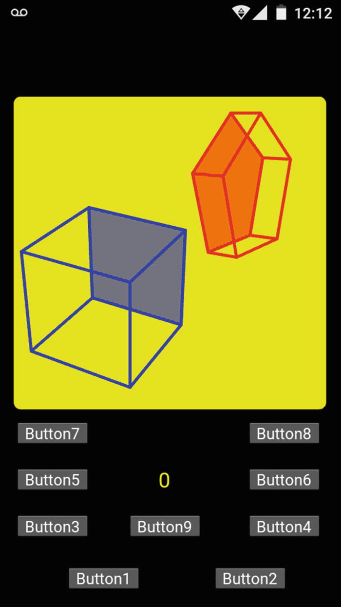
Listing 5-5The main.py Code Listing