
2
Simulation Practice
In her novel Birth of a Bridge, the French writer Maylis de Kerangal recounts a human adventure: that of building a bridge in an imaginary California. Sneaking into the psychology of the characters with subtlety, she paints a portrait of women and men accustomed to the mud of the construction sites and the adventures, technical or human, of a civil engineering project. She described Georges Diderot, the engineer in charge of the construction project, in these terms:
[He was] not a supersonic brain lubricated with force diagrams, functions with multiple variables, derivatives, strength-of-material analyses, Euclidean spaces and Fourier series. […] What filled him with joy was operating the lifesized fulfilment of thousands of hours of calculations… [KER 14]
Before carrying out this “lifesized fulfilment”, engineers build confidence in calculation tools and define the rules of practice for numerical simulation. This chapter aims to present them briefly.
When developing a computational model, engineers generally examine the different options that allow them to represent the system under study. A good knowledge of the models is generally sufficient to make the most appropriate choice of equations for the situation concerned. Their practice of simulation, oriented towards the modeling of real systems, often confronts them with the limits of model validity, for example when:
- – the equations on which they base their calculations do not reflect all the physical phenomena they wish to represent;
- – the systems they are studying (aircraft, ship, turbine, etc.) have a very complex geometry that requires simplification that can be calculated;
- – the experimental data available to them are sometimes incomplete and/or inadequate to inform the parameters of the models they implement.
In addition, some numerical models built by engineers represent the physics studied, but do not lend themselves to effective calculation with the computer resources at their disposal, particularly when:
- – computational times are incompatible with the schedule of an industrial project;
- – data management exceeds the processing and storage capacity available in the enterprise.
Mathematicians, physicists and computer scientists are working with engineers on research that aims to bypass or even push back these limits. Let’s see how they proceed to validate and improve numerical methods.
2.1 Validating a simulation
Before being used industrially, a calculation method is validated. The aim is, on the one hand, to ensure that the numerical method gives the expected results for the equation on which it is applied, and, on the other hand, that the modeling used is in agreement with the physical phenomena it represents.
2.1.1 Demonstrating a theorem
Before their use by engineers, theoretical results on numerical methods help to establish the validity of simulations. These results provide, when possible (which is not always the case), answers to theoretical questions:
- – Is there a solution to the equations of a physical model? If so, under what conditions?
- – Is this solution, when it exists, unique? Can we find more? If so, how many – and under what conditions?
- – How does the solution(s) behave: is it regular like the movement of a pendulum or does it change in a jerky way like the signal of a seismograph?
The properties of the equations are established by logical proofs. The French mathematician Cedric Villani recounts, for example, the genesis of a theorem proving the properties of an equation. Years of research were undertaken to establish a result useful to the scientific community and later to engineers [VIL 12]. His story also illustrates different qualities of the research mind. The mathematician has an idea of the result before he has the elements to achieve it. He advances towards this objective by means of an intellectual thread accompanying his walks through the labyrinth of demonstrations. His thought murmurs: “the solution is there, I feel it…” – until he is able to say with certainty: “I know it”. Like a blues musician, whose sometimes systematic work on musical phrases is carried out during dazzling improvisations, he uses his knowledge of theoretical results and his experience of demonstrations. It exploits his ability to build bridges between concepts, to use logical truths shown by others in different fields – as an artist sometimes draws inspiration from science, philosophy or literature to create. His path towards the result is woven of comings and goings, ups and downs, pauses and jumps – rugged, full of doubts as well as certainties from within a thought – and sometimes incomprehensible or inexplicable at first. He takes the time for long intellectual exchanges with Clément, a young researcher who establishes, for example, valuable intermediate results – the final theorem is signed by these two contributors! He presents his work to colleagues around the world at conferences or brainstorming sessions during which demonstrations (sometimes incomplete, awaiting a specific point of evidence to come later) are dissected and entrenched to ensure that they are well founded. The demonstration is thus being built little by little. The researchers’ adherence to the path to be followed is consolidated by their exchanges; the intermediate stages are crossed or completed to establish a final theorem, welcomed by the scientific community.
Existence, uniqueness and regularity are above all of practical interest to the engineer. Knowing that a solution exists ensures that there is a meaning to calculating it… and, when it is unique, it attests that methods to do so can be effective for that purpose. Knowing the conditions that guarantee a single solution, or not, to an equation allows us to step back from the result of a calculation. This theoretical knowledge builds confidence in simulation beforehand. The comparison of a calculation with other results, simulations or experiments, can then ensue.
2.1.2 Confronting points of view…
A model can be validated by comparing the results of a calculation with data considered reliable and usable, from an analytical solution or another calculation used as a reference. In this case, it is a question of verifying that the proposed modeling gives precise numerical results. The reference it is compared with is considered reliable.
This is the case in the following example. In order to recover heat transported by two fluids that cannot mix, the chemical, energy, food and other industries use heat exchangers (Figure 2.1). Some exchangers are made up of several hundred or thousand tubes containing one fluid and bathing in another. In a small volume, the cumulative surface area of all the tubes allows significant thermal energy exchanges. For some industrial installations, demonstrating the integrity of exchangers under accident conditions is one of the many elements that contribute to a safety analysis.

Figure 2.1. Heat exchangers are widely used in energy production or industrial chemistry processes. Depending on their size, they contain from a few tens to a few thousand tubes (Source: www.123fr.com/Munlilika Poroon, Weerapong Khodsom)
During an earthquake, for example, the entire exchanger is shaken by the movements of the earth. A calculation can account for this; however, modeling all the tubes and fluids contained in an exchanger produces numerical models that are impossible to calculate.
Broc and Sigrist [BRO 08, SIG 08b] have developed a calculation method that significantly reduces simulation times, while ensuring its use by engineers to anticipate these exceptional situations. The proposed solution is based on an equivalent physical model that does not require the entire geometry of the exchanger to be detailed. How? By taking advantage of the repetitive and periodic nature of the arrangement of the tubes, as well as their large number: using a method known as “homogenization”. This mathematical model describes the behavior of the tubes and surrounding fluid on average in a given volume, while the complete model takes into account the fluid and all the tubes contained in this volume (Figure 2.2).
In a simple configuration, a network of 100 steel tubes, organized in squares and bathed in water, two calculations are possible. The mathematical expressions used in both cases are given below, simply to highlight their difference. The quantities to be calculated are the movement of the tubes, noted U(t), and the pressure in the water, noted P(t):
- – the calculation with the complete description of all tubes is written:
The formula involves the mechanical energy carried by the tubes and the fluid: it is contained in the matrices in the equation;
- – the calculation with the average description of the movement of the tubes is written:
It also covers tube movement and water pressure. The description of mechanical energy uses a different mathematical model than the previous one. The average behavior of the tubes is indicated by a number, noted Bs representing the containment of the network, the fluid space in which the tubes are immersed, constraining their movement. The matrices have more complicated writing, but involve fewer unknowns: there are 21,000 in the first case, compared to 3,000 in the second. The calculations thus last almost ten times shorter with the homogenization method.
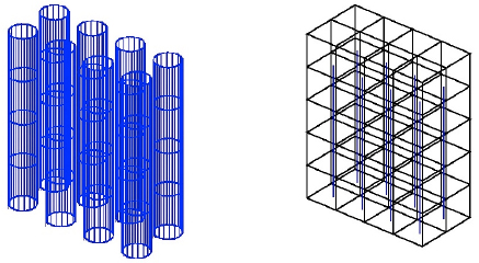
Figure 2.2. Principle of a homogenization method (on the left a group of tubes whose dynamics are described individually; on the right the same group is described on average) [BRO 08]. For a color version of this figure, see www.iste.co.uk/sigrist/simulation1.zip
The next step is to verify that both models give calculation results, if not identical, at least very close, which is indeed the case (Figure 2.3). The calculation representing all tubes and water is used as a reference: the method and the model it implements are considered as such by the engineering community. It is about the new method proving itself: what it does! The figure shows a possible movement of the tubes, among others, whose effect is visible on the pressure field. The two calculations also give very similar results, both on the frequency of the movement and on its shape.
Two different mathematical models can thus be used to represent the same physical phenomenon with similar accuracy, under certain validity assumptions. A series of tests builds confidence in the proposed models: comparison with a reference calculation for various configurations is one of them.
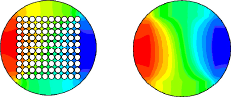
Figure 2.3. Comparison of the complete and average calculation methods for a tube bundle [SIG 08b]. For a color version of this figure, see www.iste.co.uk/sigrist/simulation1.zip
The simulation method is successfully used to study the seismic behavior of a real heat exchanger [SIG 08b]. It reaches a maturity considered sufficient to then be integrated into an engineering calculation tool.
2.1.3 Relying on experience
In other situations, the validation of a calculation method can be obtained by comparing the simulation with the result of an experiment in which a particular physical phenomenon is isolated.
In order to validate a hydrodynamic model of a ship’s rudder, Ducoin et al. [DUC 09] proposed a device to visualize the movement of a lifting profile – or foil – placed in contact with a flow. The latter is placed in a hydrodynamic tunnel to accelerate a water flow and make it reach the desired speed. The foil movement is driven by a motor that varies the angle of incidence according to a specific set point. A camera is used to visualize the vortices developing in the flow – as well as the possible formation of cavitation (Figure 2.4). A force sensor provides access to the coefficient of lift, which characterizes the effectiveness of the profile in recovering flow force to propel, stabilize or steer a vessel.
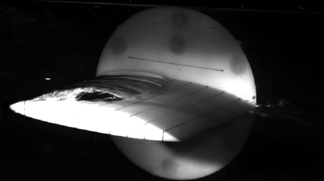
Figure 2.4. Experimental study for the hydrodynamics of foil [GAU 13]
The simulations of the experiments are based on an incompressible and slightly turbulent fluid flow model, represented by the so-called “Navier-Stokes equations”, which we will present and explained in Chapter 2 of the second volume. Cavitation, the formation of air bubbles in the water, is feared by propeller designers because it causes noise and the erosion of the propeller. It is not modeled in this calculation, but it is possible to detect the moments when it appears, that is when the pressure in the fluid becomes close to that which initiates the formation of bubbles (this phenomenon occurs in areas where water undergoes a high acceleration).
The calculation reconstructs the fluid flow lines at different times and highlights the nature of the flow (Figure 2.5). The physical analysis reveals two well-documented phenomena in the hydrodynamics of bearing profiles:
- – at the incidence of 5°, the flow changes from a regime where the fluid layers regularly slide over each other by rubbing against each other to a regime where their behavior is more irregular. Physicists talk about “laminar/turbulent transition”;
- – at an incidence of 13°, the flow is no longer stable: it separates from the profile into vortices of variable size, which are then conveyed down the flow. When the flow is no longer attached to the profile, the lift experiences significant fluctuations leading to the vibration of the foil, potentially causing noise and wear.
Experimental databases are available to naval architects to predict flow separation. A simulation such as this one can be useful to reliably complete the missing information.
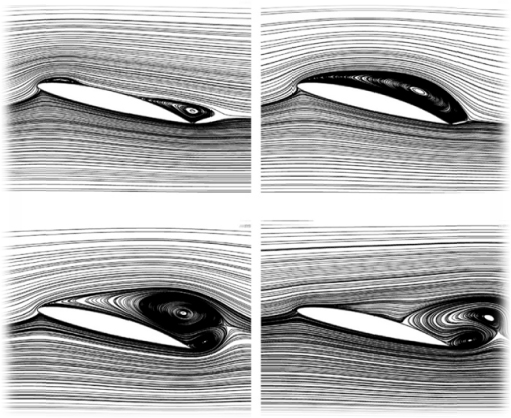
Figure 2.5. Hydrodynamic simulation of the load-bearing profile [DUC 09]
The calculation gives access to the coefficient of lift as a function of the foil’s angle of incidence (Figure 2.6). The comparison of the calculation with the experiment highlights the limits of the model and gives access to its precision: the gaps observed between simulation and observation are explained and quantified.
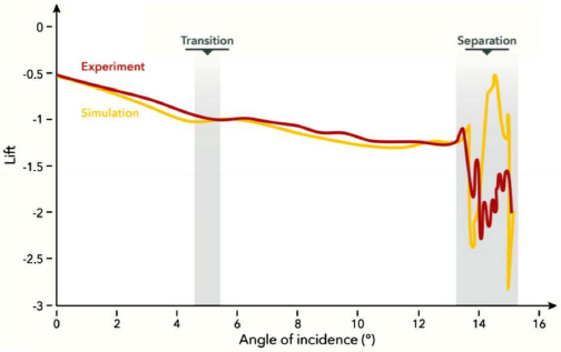
Figure 2.6. Comparison of a flow calculation with an experimental result [DUC 09]. For a color version of this figure, see www.iste.co.uk/sigrist/simulation1.zip
2.1.4 Changing point of view
Theoretical knowledge and the validation of calculation results by comparing them with numerical or experimental data guaranteeing the reliability of the numerical simulation, which can be used for real systems. Engineers dream of it, simulation tool editors promise it: it would be possible to simulate everything, or almost everything, from pre-dimensioning in preliminary design to dismantling at the end of a product’s life! When the virtual becomes real, it sometimes confronts practice directly with theory, without going through a physical demonstrator to scale or a model. In many cases, however, test means or procedures are implemented throughout the industrial design process.
Some tests are carried out on finalized products or constructions: a crash-test on a car or train set validates the design with regard to certain safety requirements; a test at sea of a ship (liner, frigate, etc.) helps to demonstrate its operational performance (speed, noise, sea-keeping, etc.) to the owners or navies who will operate it. Other tests are carried out on models in order to validate an architecture concept, a design methodology. This is the case of seismic testing of a building, impact on a cabin, endurance of an engine. The purpose of the tests is broad and their use varied!
Let us give representative examples of problems shared by many industrialists. In order to support a given program, in which economic or safety issues are at stake (for example, the next long-haul aircraft or the new generation of submarines), some industries, such as aeronautics and naval, use impressive means (Figure 2.7): wind tunnel or ship basin for aerodynamic or hydrodynamic tests on models of aircraft, ships – but also bridges, trains, cars, etc.

Figure 2.7. Tests and model calculations are complementary (Source: © ONERA, ONERA/Airbus). For a color version of this figure, see www.iste.co.uk/sigrist/simulation1.zip
For example, the test makes it possible to optimize fuselage and hull shapes and illuminates design choices – as the simulation allows. The testing resources also meet a forward-looking desire. It is then a question of exploring new concepts in order to eventually turn them into innovative objects, proving their advantage in a competitive market or a theatre of operations.
The constant progress of simulation, the rules of good practice and the confidence built up by long-standing experience feedback make it possible to consider doing without certain tests. Is this the end of the demonstrators? Patrick Wagner, Wind Tunnel Director of ONERA*, explains the industrial interest of test facilities:
In the aeronautics industry, the rise in maturity and reliability of flow calculation tools has changed the way tests are conducted. The simulation makes it possible to design an experimental sequence, to select among many possible combinations (flight altitude, incidence, cruise speed) the most relevant for the expected demonstration. It also helps to choose the fuselage lines that are then tested in the wind tunnel.
The calculation allows us to choose some of the most aerodynamic shapes, and the test takes over to determine which one will have the best performance and can be selected for industrialization.
In some cases, the models tested can reach a span of up to 4 meters and operate at Mach number close to the unit (the flow velocity is thus close to the speed of sound in the air). In France, ONERA’s largest wind tunnel, located in Modane, requires a power of 100 MW for operation (for comparison, a hair dryer requires about 1 kW, or a hundred thousand times less!).
The economic balance of these test facilities remains difficult to handle, and its opening to many customers, civil, military or private aeronautics, is one of the keys:
For some flight configurations, for example, where fluid layers around the wings are separated, the turbulence models used in the simulations lose their reliability. The flow separation must be estimated with the greatest precision to ensure the safety of the device. This is the case, for example, when manufacturers want to offer innovative shapes, for example to reduce aerodynamic drag […] and fuel consumption. In these situations, only wind tunnel tests provide access to precise information that is still inaccessible to the calculation. Unlike the United States, France has chosen to retain its testing resources for its aeronautics industry. While this type of testing and resources is developing in China, the United States has decided to step back and equip itself in 2009 with modern equipment, for an initial investment of 600 million dollars!
Shipbuilders are also developing simulation models, in addition to tank tests, to improve both technical and economic efficiency. The digital basin refers to a set of tools for simulating marine hydrodynamics. It complements, but does not completely replace, the physical test tank. It is relevant for manufacturers and experimenters to have proven calculation methods at their disposal, allowing them to explore more variants during the design process, while reducing the number of physical tests – or by proposing the most suitable tests to demonstrate the expected performance. Numerical calculation makes it possible, on the one hand, to generate a large amount of data, useful for proposing an optimal hull design for example, and, on the other hand, to define the most appropriate physical test to validate the selected design (shape of propellers, hulls or appendages).
These two examples show that tests and simulations do not conflict, but work together. In aerodynamics, the calculation allows, for example, to correct a wind tunnel bias. For example, during a test, the model under test is held by a mechanical device that can induce disturbances on the observed flow. The simulation can also extrapolate the results obtained during the test (at the scale of the model) to the real conditions (at the scale of the real aircraft).
A tool of the future will undoubtedly be the combined use of simulation and experimentation:
‘Data assimilation’ techniques, also used in meteorology, will contribute to this. They make it possible to build a numerical model whose known modeling limits are corrected by experimental data, for example to account for turbulence.
Hybridization between equation and data modeling is one of the most certain and promising evolutionary paths for calculation – we will examine different examples in the second volume.
When digital simulation contributes to the demonstration of the safety of installations and the safety of means of transport, its use is part of a regulatory framework, enacted for example by a safety authority or a certification office. The methods are periodically reviewed according to technical innovations, industrial needs, limits observed on an approach, etc. A regular exchange within networks of experts from different entities (public, private, academic, industrial, independent, etc.) remains a guarantee of good simulation practice.
2.2 Maturity of a technique
The birth of a bridge, from its design to its inauguration, follows, like any usable and marketable product, an unpredictable path: thought of in a rational way, step by step, it is often realized differently [ENG 03]! However, the development of new techniques, such as numerical simulation, can conform to a standard approach that accompanies their quality, attests their reliability and establishes their robustness.
The TRL (Technology Readiness Level) scale, for example, makes it possible to assess the maturity of a technology, from the early stages of its development to its integration into a complete system, its industrialization and its commercialization. Originally set up by NASA* to streamline the development of American space programs, it is increasingly used in all fields of innovation. It makes it possible to adopt a common language for sometimes distant technical fields. This nine-level scale can be understood as a logarithmic scale of the investments required to deploy a technique.
The closer we get to the final product, the greater the investments required to produce and market it:
- – level 1 (lowest) corresponds to the stage of an idea, concept or physical principle;
- – level 9 (highest) corresponds to the product marketed and used, based on this idea or principle.
Let us take the example of the development of a simulation method (Figure 2.8). The emergence steps (TRL 1–3) lay the theoretical foundations of the calculation: the mathematical model, the numerical method and the associated algorithm. The development steps (TRL 4–6) ensure the validation of the method, in cases representative of future industrial uses of the calculation, with computer resources similar to those implemented in a project. The maturation steps (TRL 7–9) accompany the integration of the method into industrially used software tools – and with the constraints that this implies, among others:
- – calculation times compatible with design deadlines;
- – consent among the users of the method regarding its accuracy;
- – reliability of the calculations and their protocol considered acceptable by designers as certification or control authorities.
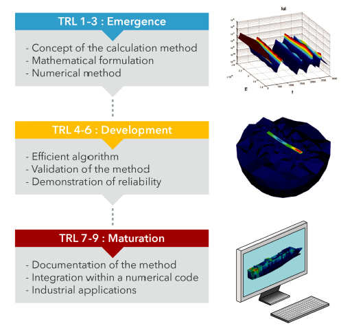
Figure 2.8. From its mathematical principles to its integration into a calculation tool: the maturation of a digital simulation technique
From the idea to its effective application with industrial means, as part of a practice documented and shared by a community, the cycle can last about 10 years1!
A developer and an editor of a calculation code release a digital tool, with a set of validation cases certifying its accuracy and maturity. More than the power of computers, simulation is useful and effective because of the skills of the men and women who use it. As with any other tool or technique, it is up to its users to integrate it into their activity, according to their own process.
The qualification of a method ensures that the calculation process is considered reliable and accurate for the desired use. It may cover elementary steps of the calculation, as observed in the previous chapter, or a calculation as a whole – usually by feedback or another appropriate means of testing, sometimes sized specifically for a product or material.
2.3 Practice, practice, practice…
While industry integrates numerical simulation at different stages of a project, the level of practice depends on many factors: available skills, feedback, technical and financial resources [DUB 16]. Let us now discover in more detail the practices of simulation.
2.3.1 The engineer’s palette
In Maylis de Kerangal’s novel, the energy of a civil engineering site unfolds in a mythological way and the main character takes the form of an engineering Hercules:
Before him, excavators warm up their motors and set themselves in motion, slowly, mechanical mastodons capable of digging a hole the size of a football field and eighty feet deep in a single day [KER 14].
The success of a project depends both on the skills held by people… and on a range of tools appropriate to each technique, adapted to various tasks. Those of numerical simulation? They are just as varied as those on construction sites and their ergonomics and use are becoming more and more intuitive. They are generally accessible within the same IT environment and include three main functionalities:
- – Modelers associate physical laws with the geometry created by Computer Aided Design (CAD). They list the model data (dimensions of the parts represented, physical characteristics of the materials used, etc.) and allow the object studied to be visualized in three dimensions (Figure 2.9).

Figure 2.9. CAD model of a violin (Source: Romain Viala, University of Bourgogne Franche-Comté)
- – Meshers ensure the discretization of the studied part, prior to its calculation. The quality of the mesh size can have a more or less significant influence on the calculation result, depending on the physical phenomena involved. In order to represent them correctly, it is essential to look for information at different points that form the mesh. For example, for turbulent flow, it is necessary to use fine meshes in the vicinity of a wall, where the flow velocity varies significantly, while looser meshes are sufficient to represent it at long distances (Figure 2.10).
Good practice rules, specific to each manufacturer, generally ensure the quality of the results. They are based both on theoretical results concerning the calculation methods used and on the experience acquired by the engineers implementing them [KRI 17]. For very complex parts, producing a mesh represents several days of work. The tools are constantly being improved in order to simplify this task… without losing quality;

Figure 2.10. Mesh preparing the wind turbine aerodynamics calculation (Source: www.gridpro.com). For a color version of this figure, see www.iste.co.uk/sigrist/simulation1.zip
- – Solvers perform the actual calculation operations. They implement assembly, storage and calculation algorithms on matrices containing information about the system under study.
The analysis of the calculation results is the core of numerical simulation. The engineers thus contribute all their know-how and technical expertise. Simulations can produce a large amount of data. It is then a matter of extracting relevant information from it. The presentation of the calculation results is specific to each simulation. Curves, diagrams, images, tables: the choice of information representation contributes to its communication, in the literal sense of the term – its transmission.
The codes for representing the results of scientific computation are the result of both regulatory requirements and proposals made by engineers to share the results of calculations and make them as intelligible as possible. The physical quantities accessible using simulation are more or less easily represented. Fluid flows lend themselves to a very visual – even spectacular! – analysis, as evidenced by many examples proposed in this book…
In the industry, a calculation is usually made to answer a design question, as we have discussed using the various examples encountered so far. In general, the simulation is then used to:
- – Justify the qualities and performance expected for a concept. This involves calculating a given physical quantity (the speed of air or water for a flow around a wing, blade, hull; the value of mechanical forces acting on an object, the deformation it undergoes in return, the intensity of vibrations, etc.) and comparing it with an acceptable criterion. The criterion is generally set out in a design guide, safety regulations, etc. The analysis attempts to conclude in a clear-cut way, notwithstanding the limitations of interpretation implied by modeling and calculation.
- – Compare operating situations and design options for a given product or system to select the one with the best characteristics. The conclusion is then established on the basis of a compromise between different requirements (technical feasibility, economic constraints, etc.).
Modeling choices and data quality can influence the calculation result. This is the result of the power of the algorithms digested by the computer as well as the physical sense and experience of the engineer who builds a digital model. In this sense, the practice of numerical simulation remains essentially human today.
2.3.2 Complementary philosophies
Different simulation tools can be implemented by engineers, depending on needs and levels of practice, and are divided into three main categories:
- – A general purpose code offers various functionalities, for renting or purchasing user licenses according to needs. The modeler, mesher, and solver are often combined in a single environment whose ergonomics are worked on to allow the widest possible use of the tool (Figure 2.13).
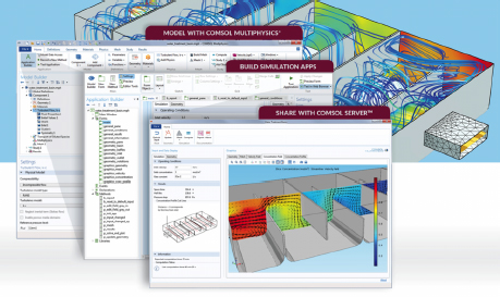
Figure 2.13. Design of a drinking water treatment basin using a generalist tool (Source: image produced with the COMSOL Multiphysics® code and provided by COMSOL/www.comsol.com). For a color version of this figure, see www.iste.co.uk/sigrist/simulation1.zip
COMMENT ON FIGURE 2.13.– The COMSOL Multiphysics® calculation code is an example of a generalist tool. It is based mainly on finite element technology – and also offers other methods to solve a wide variety of problems. Specialized in multi-physical coupling, it covers many fields: mathematics, mechanics and acoustics, fluid and thermal, chemical, electromagnetic, optimization… It offers its users a unified interface and allows them to create “business” interfaces specific to each user. It integrates programming features, such as Matlab®, Java® and Excel® and dialogues with computer languages such as C/C++ and FORTRAN.
Designed and marketed by a calculation solution publisher, it applies to many technical fields – for example, in mechanics, it allows shared analyses to be carried out by users from different industries. Its evolutions, its IT optimization and its development strategy are those of the publisher. The latter adapts to the demand of its users and also offers them innovations;
- – An expert code is based on more limited functionalities, generally focused on specific problems, specific to a given technical field or industrial sector – or even a particular company. It is developed and validated by an engineer or a team of engineers who use them, and requires specific know-how. It is the responsibility of the company that bears the development and maintenance costs, which implies, depending on the case, more or less significant investments. This tool is strategic for the company and is part of its assets. The latter often has exclusive use of it, and may, depending on the needs of a project, transfer operating licenses to a partner or supplier;
- – Open-source code offers an interesting alternative to the previous tools. It is generally developed by a technical and scientific community that makes the tool available under the terms of an operating license. The latter may provide for the transfer into the public domain of a development carried out by a particular user. It offers a more open working environment than commercial codes, for sometimes equivalent performance, including on industrial subjects. It also allows the development of business tools: researchers and engineers use them for research purposes and contribute to a global scientific network. As a common and open platform, they are also particularly suitable for collaborative research projects.
In the academic world, some researchers are developing open-source simulation tools with very limited human and financial resources compared to the economic power of industrial code publishers. Peggy Varnière and Dimitri Komatitsch, researchers in astrophysics and geophysics at CNRS*, are contributing to the development of the calculation codes used by their scientific communities and thus testify:
‘Open-source’ computation codes are dedicated to a given problem. They can be shared by a scientific community, depending on the needs and uses that researchers imagine. The philosophy is to share tools and ideas for improvement […] while respecting each other’s practices and the stability of the tool.
The constraints and opportunities encountered in the academic and industrial communities are different. They do not necessarily oppose each other: they feed and respond to each other. Collaborative development also shows that the cooperation model can be as effective as the competition model in creating and sharing intellectual assets.
The tools offer functionalities that are more or less open to their users, depending on the needs. Co-simulation techniques allow different tools to be discussed and their specificities to be taken advantage of. For complex simulations, the calculation results can generate a very large amount of data and having sufficient storage capacities has also become an issue for the industrial use of the simulation.
2.3.3 Users with different needs
In order to be used optimally, numerical simulation requires many skills covering both the research sector (researcher in mathematical modeling, applied mathematics, computer science, physical sciences, etc.) and that of industry (research and development engineer, simulation/calculation technician or engineer, etc.) or services (scientific calculation expert and advisor).
Its use by companies is varied and depends on their size as well as their sector of activity. Numerical simulation is used by many engineers in the industry every day. It supports the design of various installations, with proven methods and tools, whose reliability has been established by long-standing practice.
Tim Morris, head of the NAFEMS* association, which brings together many simulation users in the industrial world, summarizes:
Most, if not all, major industrial groups nowadays master this technique in general. They have tested, validated and integrated it into their design and manufacturing process. The engineers know the potentialities of simulation, the costs of this technique and also the limits and pitfalls of the tool.
Mechanics in general is the most widespread application (Figure 2.14) and other fields, such as electromagnetism or electrochemistry, are emerging in this field. It is a question of gaining design margins, in order to reduce manufacturing costs, or to gain in performance – and also to integrate new standards, in particular environmental ones.
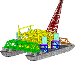
Figure 2.14. Digital model for the transport of a platform at sea (Source: © TechnipFMC). For a color version of this figure, see www.iste.co.uk/sigrist/simulation1.zip
Simulation, as we have mentioned on several occasions, contributes, for example, to:
- – optimizing mechanical strength to lighten a means of transport;
- – recognizing normal (wind, swell) and sometimes degraded (storm, earthquake) operating conditions to calculate the size of a civil engineering structure;
- – integrating material property data predicting the life of a renewable energy platform;
- – using eco-friendly materials to design a system that is better for the environment, etc.
However, numerical simulation is not exclusively reserved for large industrial groups. This technique is available to small and medium-sized companies, or even very small companies, for different uses. Some have taken the step and invested in this technology, for particular reasons – for example, companies in the plastics or metallurgy industries, driven by orders from major industrial accounts.
Using a new material, lightening and making a product last, optimizing a production line or manufacturing process (molding, machining, forging, etc.): SMEs use simulation to gain competitiveness. Calculations allow giving very good indications in order to improve a practice, a process or a design (Figure 2.17).
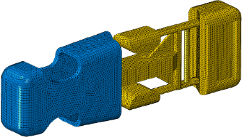
Figure 2.17. The simplest parts can be studied using numerical simulation (Source: EC2 Modélisation, www.ec2-modelisation.fr). For a color version of this figure, see www.iste.co.uk/sigrist/simulation1.zip
COMMENT ON FIGURE 2.17.– For an SME in the plastics industry, it may be difficult to invest in numerical simulation. However, finding an expert provider of this technique can help implement it in order to improve the design of its products. The example presented above is a mesh designed for the study of the strength of a backpack loop: a design optimized in terms of material consumption per unit produced is very interesting for the manufacture of a large series.
Amélie Roux, business manager of a simulation company for very small and medium-sized companies, asserts that:
In some industrial sectors, such as construction, particularly wood-based, numerical simulation is still not very widespread. Economic actors who develop innovations use them to reduce the number of prototypes and certification tests – and gain efficiency in the broadest sense! Service outsourcing is then the preferred way to access the simulation.
The limits to the use of simulation are the initial investment cost, machines and software licenses… and humans! Publishers offer rather easy access simulation tools, adapted to different fields and that do not impose too many IT resources and too much investment.
Higher education institutions offer training adapted to these techniques. The offer is there, the difficulty is sometimes to meet a demand within SMEs and VSEs. For SMEs, the challenge is twofold: to find skills and organize dialogue between simulation practitioners (typically a young graduate, technician or engineer, trained in this technique and rooted in digital culture) and those with long-standing know-how and experience. It is a question of finding in the company a winning duo that will know how to dialogue around the simulation in order to use it as well as possible!
For VSEs (very small enterprises), it is often difficult to invest in this technique, but it is possible for them to find support from qualified service providers: the cost of study can then become affordable… and profitable! Thus, numerical simulation is not reserved for science researchers or industrial engineers. VSEs specialized in simulation practice can accompany other VSEs in their use (Figure 2.18). With versatile tools, allowing a representation close to reality, simulation helps to shed light on the design issues expressed by SMEs and VSEs, who increasingly trust it.
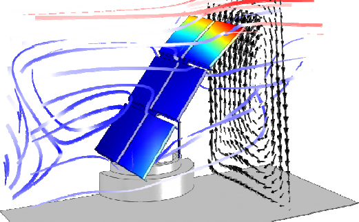
Figure 2.18. Simulation of the flow around a solar panel (Source: image made with the COMSOL Multiphysics® code and provided by COMSOL, www.comsol.com). For a color version of this figure, see www.iste.co.uk/sigrist/simulation1.zip
COMMENT ON FIGURE 2.18.– The model presented in the figure is developed by a VSE specialized in the field of scientific computing. It is designed according to the customer’s expressed need: it is a matter of checking the integrity of a panel subjected to the effects of the wind. The simulation calculates the air flow around the panel and studies the resulting deformations and pressure (in the image, the bands indicate the path taken by the wind around the panel and the color shades represent the deformations of the panel). The calculation provides useful information at a reduced cost in order to validate a design.
The effectiveness of the support lies in the dialogue between simulation experts and the customers’ knowledge of the product. It is a matter of taking the time to define the problem, to target the variables of interest and to build a numerical model with shared assumptions. It is in this spirit that many experts work with their clients to use simulation in their business. Thomas Clavet, consulting engineer in simulation, explains:
Understanding a customer’s need allows us to propose a calculation solution that will allow them to obtain results in a relatively short period of time. The in-depth knowledge of a versatile tool makes it possible to build ‘simple and fast models’ thanks to an adapted simulation strategy that generates relevant data and guides design choices.
Numerical simulation can seem complex, expensive… and would be opposed to a traditional practice! In order to build trust in this technique, many service providers offer their customers who are using it for the first time simple, three-dimensional models. The calculations allow us to see the part or product concerned (Figures 2.17 and 2.18) and give quick results. Simulation customers consider it capable of replicating a test or proposing a more efficient design: it then acquires its technical validity and economic interest.
As a research center, a major industrial group and a small and medium-sized company, numerical simulation is becoming a global technique, with the following chapter describing some of its features in detail.
- 1 The communication of innovation is often based on accelerating the production of knowledge, or on the dissemination of techniques at a rapid pace… With digital technology, we have undergone radical changes in production and communication methods in a few decades. And in some cases, we are far from using the innovations promised by some! It takes even longer for people to develop a technique – and for others to appropriate it when it corresponds to a need – than for the effects of announcements around innovations. For a simulation method, the full time of maturity can take a decade (for example, when the proposed methodology must be integrated into a regulatory corpus, the development and validation of which takes time). However, the gap between academic innovations and their industrial use is narrowing: in some industrial sectors, a calculation method mastered by experts who have contributed to their development can thus find specific applications more quickly, in a few years for example.