P. Greaves Offshore Renewable Energy Catapult, Northumberland, United Kingdom
Abstract
Offshore wind turbine blades can differ significantly from their onshore counterparts. This chapter discusses these differences and describes the methodologies that are used during the design of the blades. The chapter covers aerodynamic and structural design, materials choice, manufacturing methods and different rotor architectures.
The blades of a wind turbine, whether onshore or offshore, must satisfy a wide range of design requirements which will often be in competition with each other. For example, the aerodynamicist would like to use an aerofoil with the smallest possible thickness in order to minimise the lift to drag ratio and maximise the energy yield of the turbine. However, this aerodynamic profile will be less structurally efficient, so more material will be required in order to satisfy strength or stiffness requirements. The overall design requirement is not to maximise the energy yield, but rather to minimise the cost of energy (generally achieved by maximising the ratio of energy yield to blade weight) whilst ensuring that the blade survives the extreme and fatigue load cases.
Many of the design drivers for onshore wind turbines are not present offshore, and so we must be careful about taking assumptions about optimal turbine designs which have been developed onshore with us when we begin to consider the design of offshore rotors. For example, there is little to choose between two- and three-bladed turbines in terms of economics – the three-bladed turbine dominates because it is less noisy and less visually disruptive than an equivalent two-bladed turbine. However, these drivers are not present offshore and the two-bladed turbine would offer significant advantages in terms of transportation and installation.
Furthermore, the cost of the turbine has a much smaller impact on the cost of energy offshore than it does onshore, as shown in Table 6.1. Trade-offs in the annual energy yield made to reduce the cost of the turbine (for example, by using a more structurally efficient aerofoil shape at the expense of aerodynamic performance) which may make sense onshore could have a negative impact offshore. On the other hand, the cost of the foundations is far larger offshore so if the loads which the foundation experiences can be reduced at the expense of energy yield then perhaps the cost of energy can be reduced. The point is that we cannot consider the rotor in isolation – the entire wind turbine system must be taken into account.
The purpose of this chapter is to provide the designer with all the tools required to model the blades, including methods of predicting the aerodynamic loading, the behaviour of the materials and the properties of the structure. These methods can be used to feed into the overall turbine model. Some of these techniques are classical; where more advanced or commercial options are available the reader will be directed to the relevant references.
The horizontal axis, variable-speed/variable-pitch turbine architecture which currently dominates will be the main focus of this chapter, as this is the type of turbine that the reader is most likely to encounter in practice.
6.2. Aerodynamics
A detailed discussion of the aerodynamics of wind turbines is beyond the scope of this chapter. Entire books have been written on the subject, so the focus will instead be on equations that are most relevant to the design of offshore turbines. Readers who are interested in the derivation of the equations can refer to the references.
Assuming we have settled on a horizontal axis turbine (that is, a turbine for which the axis of rotation is aligned to the wind direction), we can begin a discussion on the aerodynamics with the stream tube concept.
6.2.1. Momentum theory
Wind turbines extract kinetic energy from the wind, as shown in Eq. [6.1].
[6.1]
The mass of the air which crosses the rotor plane every second is ρAv, where ρ is the density of air, A is the area of the rotor plane and v is the wind velocity. Substituting this into Eq. [6.1] we obtain the equation for the power available in the wind, given in Eq. [6.2].
[6.2]
Fig. 6.1 shows an annular axial stream tube of air crossing a wind turbine rotor. It has four cross-sections, with Section 6.1 some way upstream of the turbine, 2 just in front of the rotor plane, 3 just after the rotor and 4 some way after the turbine. We can assume that the pressure p is the same at Sections 6.1 and 6.4, and that the velocity v is the same at Sections 6.2 and 6.3. Between 2 and 3 energy is extracted by the rotor so the pressure will drop. If we apply Bernoulli's equation and note that the force dFx is equal to pressure p multiplied by the cross-sectional area of the stream tube 2πr dr then we can arrive at Eq. [6.3], in which ρ is the air density.
Figure 6.1 Axial stream tube for different axial induction factors.
[6.3]
Let a, the axial induction factor, be defined by Eq. [6.4]. It can also be shown that v1 and v4 can be calculated using Eq. [6.5].
[6.4]
[6.5]
Substituting Eqs [6.4] and [6.5] into Eq. [6.3] we can obtain Eq. [6.6] for the axial force on an annular ring. Noting that the power is the force multiplied by the velocity at the rotor plane, we can use Eq. [6.7] to calculate the power as a function of the axial induction factor.
[6.6]
[6.7]
By differentiating Eq. [6.7] it can be shown that the maximum power is extracted when a is equal to 0.33.
The air exerts a torque on the blades, which means that the blades exert an equal and opposite torque on the air. Upstream of the blades, there is no rotation. In the wake of the turbine, the wake rotates with an angular velocity of ω. The torque on an element dT is equal to the rate of change of the angular momentum of the air crossing the rotor disk, which is given by Eq. [6.8], in which I is the moment of inertia of the stream tube at the rotor plane and is the mass flow rate through the annular stream tube. The axial induction factor a′ is defined in Eq. [6.9], where Ω is the angular velocity of the rotor.
The blade sheds vortices from the tips, which reduces the forces exerted on the blade. The Prandtl tip loss factor Q, defined in Eq. [6.11], can be used to correct for this. The rotor radius is represented by R and the number of blades by B.
[6.11]
With tip loss accounted for, the equations for the axial force and torque on an annular ring are given by Eqs [6.12] and [6.13].
[6.12]
[6.13]
6.2.2. Blade element momentum theory
In practice, the rotor does not operate at the optimal inflow conditions all the time. Under circumstances other than optimal inflow, blade element momentum theory can be used to calculate the aerodynamic loading. Other, more complicated, methods of calculating these loads are available (for example lifting line models and computational fluid dynamics) but they are much more computationally intensive than bladeelement momentum theory. For this reason it is the most common method of calculating the loads on the rotor blades, and provided the assumptions that it is based on are not violated it is in agreement with the more complex methods.
Figure 6.2 Resultant relative velocity at a blade element.
The theory assumes that lift and drag lookup tables are available for the aerofoils used on the blade, with lift coefficient CL and drag coefficient CD plotted as functions of angle of attack α for the relevant Reynold's numbers. These tables are obtained either by wind tunnel tests, CFD of 2D aerofoil profiles or by using panel methods. It is also assumed that there is no mixing between the annular stream tubes which the rotor is divided into.
An element of the blade is shown in Fig. 6.2. We can see that the resultant relative velocity W can be calculated using Eq. [6.14].
[6.14]
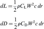
The lift force dL and drag force dD acting on an element can be found using Eq. [6.15]. The forces can be resolved into the axial force and torque using Eqs [6.16] and [6.17].
[6.15]
[6.16]
[6.17]
We now have four equations for the axial force and torque on the blade element which can be solved iteratively. Eqs [6.12] and [6.13] are derived from momentum theory and Eqs [6.16] and [6.17] are derived from the forces acting on the blade element.
We make an initial guess for a and a′, and then using these values we can equate [6.12] and [6.16] to obtain an expression for the next value of a and equate [6.13] and [6.17] to get an expression for the next value of a′. These expressions are given in Eqs [6.18] and [6.19].
[6.18]
[6.19]
The lift and drag coefficients for the next iteration are found using a lookup table for the aerofoil in question, with α being found from the inflow angle ɸ and aerofoil set angle β as shown in Fig. 6.2. The process continues until the difference between successive values of a and a′ are within a predefined tolerance.
6.2.3. Optimal blade design
The optimal blade geometry for variable-speed operation can be derived analytically, but this will not be presented here. The interested reader can consult references [2] and [1] for the full derivation of the equations for the optimal blade geometry.
The optimum value for the axial inflow factor has already been shown to take the value of 0.33 for the case when drag is ignored. However, as the value of the axial inflow increases so does the thrust loading on the rotor. Potentially this can result in a higher cost of energy as the more heavily loaded rotor will require more material, so we will present the equations here for the case when a can take values other than 0.33, as described in reference [1].
Eq. [6.20] define some variables which describe the blade. The tip-speed ratio λ is defined as the ratio between the tip speed of the blade (found from the radius R multiplied by the rotational speed Ω) and the upstream wind velocity v1. The lift drag ratio k is the ratio of the lift coefficient CL to the drag coefficient CD at the angle of attack for which this value is maximum. This will vary along the length of the blade, as the same aerofoil cannot be used across the whole span because of structural design constraints. Finally, x is the proportion of a spanwise location r to the blade length, with 0 being the centre of rotation and 1 being the blade tip.
[6.20]
The tangential inflow factor a′ for optimal operation with a given distribution of k, tip-speed ratio λ and axial inflow factor a is given by Eq. [6.21]. As discussed earlier, k will vary over the blade span.
[6.21]
The tip loss correction factor Q defined in Eq. [6.11] accounts for the effect of losses due to the tip vortex. The number of blades is given by B.
We can then calculate the local blade geometry parameter Λ which allows us to find the chord length c and local inflow angle φ using Eq. [6.22]. The blade set angle β can then be determined from the angle of attack α at which k is maximum and φ.
[6.22]
The power coefficient CP is found using Eq. [6.23]. The thrust coefficient CT is found using Eq. [6.24], and the moment coefficient CM at span proportion x0 can be calculated from Eq. [6.25].
[6.23]
[6.24]
[6.25]
These equations are useful in the context of design studies, but they cannot be used to calculate loading off the optimal operating point. For this case, the equations must be solved iteratively using blade element momentum theory.
6.2.4. Effect of tip-speed ratio
The tip-speed ratio is the ratio of speed that the tip of the blade travels at to the wind speed. Onshore, the speed of the tip is limited by noise considerations to around 75m/s, but in principle the turbine designer can allow the tip to travel faster offshore because the turbine can be noisier.
This has several benefits for the design of the turbine. As the tip speed increases for a given power output, the optimal blade profile becomes more slender, potentially reducing material usage in the blades. More importantly, the turbine produces less torque for a given power output. This will reduce the steady loads in the hub, the gearbox (and/or generator), the nacelle bedplate, the tower and the foundations. This has implications for both the top head mass and overall material usage.
However, we cannot increase the tip speed indefinitely because of leading-edge erosion and stability concerns. Blade erosion occurs at the leading edge near the tip where the incident velocities are highest, and is caused by dust or rain particles impacting the blade surface causing damage to the blade coating and eventually the underlying structure. Leading-edge erosion will be discussed in more detail later.
6.2.5. Effect of number of blades
From an economic point of view, two- and three-bladed rotors offer a similar cost of energy. The slight reduction in the power coefficient caused by a two-bladed rotor is balanced by reduced material usage in the blades (partly because there are fewer blades and partly because the optimal design for two blades has a higher chord length, and therefore thickness, increasing the structural efficiency).
One drawback of two-bladed turbines is that the effects of wind shear and tower shadow occur at the same time when the rotor is in the vertical position, which has serious implications for fatigue loading. This can be reduced with individual blade pitch control or the use of a teeter hub.
The rotor has also a different moment of inertia depending on the azimuth angle, which can be challenging from a dynamic perspective (although modern control systems are better placed to address this issue than those used in the early days of the onshore industry, when the two- versus three-blade argument was at its height).
Three-bladed turbines dominate onshore because they rotate more slowly for a given swept area, which reduces noise and makes the turbine less visually intrusive. As discussed earlier, their dynamic behaviour is also easier to model. These factors led to three-bladed turbines becoming the norm onshore, and their use has continued offshore because revolutionary designs increase the risk associated with wind farm projects.
Two-bladed turbines are now being revisited, with several companies developing large offshore platforms. A key benefit of two-bladed turbines relates to transport and installation. With a two-bladed turbine, the nacelle and rotor can be installed inone lift, whereas three-bladed turbines need at least two lifts, one of which will involve a non-vertical interface. This will either be to fit the rotor (if the nacelle is installed followed by the rotor) or to fit the third blade, if a ‘bunny ears’ installation is used (this involves transporting the nacelle with hub preattached and two blades installed, pointing upwards like a rabbit's ears).
6.2.6. Upwind versus downwind rotor
Onshore turbines tend to have upwind rotors because they reduce the effect of tower shadow, a significant source of noise and fatigue loading. The latter problem can be reduced through the use of truss towers, which are generally not acceptable onshore for aesthetic reasons. Teeter hubs, in which the blades are allowed to pivot about an axis that is perpendicular to the axis of rotation, greatly reduce the fatigue loads at the root at the expense of additional complexity.
This means that offshore, with the aesthetic and noise constraints removed, downwind rotors become more attractive. The design of the blades will be less likely to be dominated by tower strike (a ‘stiffness-driven’ design) and more likely to be driven by the strength. This could potentially lead to a reduction in blade weight.
Also, wind turbine rotors are generally ‘coned’ in order to increase tower clearance. For an upwind rotor, coning the blades means that the centrifugal force acts to create a bending moment in the same direction as the aerodynamic bending moment. For a downwind turbine, the centrifugal forces act to reduce the aerodynamic bending moment.
Finally, a downwind rotor can potentially offer the benefit of a free-yawing turbine. In this case, the yaw dynamics must be carefully considered, and power take-off over a rotating boundary at the MW scale is not trivial.
So far, offshore turbines have mainly evolved from onshore designs so downwind rotors are something of a rarity.
6.3. Materials
Many materials have been used for wind turbine blade construction. In the early days of the industry, steel was used because of its high stiffness and well-understood processing techniques. However, its specific strength (yield strength/density) is too low and it is too difficult to form twist optimised blades. Aluminium was also used but it was found to be too fatigue-sensitive and insufficiently stiff. Wood is widely used on smaller turbines but its properties are generally too variable to produce reliable designs, so although it has excellent fatigue properties it is rarely used in significant quantity for modern wind turbine blades.
The prevailing materials for modern wind turbines are fibre-reinforced plastics, which consist of a polymer matrix reinforced with fibres. They have been selected for their high specific stiffness, good fatigue properties, low density and the ability to tailor the material properties in different directions.
E-glass is the most commonly used reinforcement material. Carbon fibre is also occasionally used as reinforcement but although it is stronger, stiffer, more fatigue-resistant and less dense than E-glass it costs significantly more so its use oncommercial wind turbines so far has been limited to local reinforcement and the blade spar. Typical properties of these two fibre systems are shown in Table 6.2.
The purpose of the polymer matrix is to bind the fibres together so that they act in unison. The polymer can either be thermosetting or thermoplastic, and both of these material types have a relatively low Young's modulus (typically less than 4GPa). However, the matrix gives the composite improved toughness.
Thermosetting matrix materials are processed by combining a resin with a hardener, which reacts with the resin to promote crosslinking between the polymer chains. This curing reaction is irreversible, so thermoset plastics are harder to recycle. The matrix materials used are typically polyesters, vinylesters and epoxies, and they have a strain at failure of around 5–8%. Polyesters were widely used in the early days of the industry, but epoxy resins are now becoming the most used type of material.
Thermoplastic matrix materials are not currently widely used for utility-scale wind turbine blades, because their large size makes it hard to achieve the high processing temperatures required for matrix materials with the required properties. The ability to recycle the blades at the end of their life more easily makes thermoplastics attractive, so finding ways to use these materials for blades is an active area of research.
6.3.1. Estimation of composite stiffness properties
The stiffness and density properties of composite materials can be estimated from those of the constituent materials using the rule of mixtures. The coordinate system shown in Fig. 6.3 is used in Eqs [6.26]–[6.29], in which E is the Young's modulus, G is the shear modulus, υ is Poisson's ratio and ϕF is the fibre volume fraction. The subscripts F and M refer to the fibre and matrix, respectively.
[6.26]
[6.27]
[6.28]
[6.29]
Figure 6.3 Blade, laminate and ply coordinate systems.
Better estimates for these properties can be obtained by developing a micromechanical model using the finite element method. However, these equations are a useful first step when estimating the effect of changing fibre/matrix properties or the volume fraction. With the composite properties known, we can then move on from the ply to calculate the stiffness properties of the laminate using classical lamination theory.
6.3.2. Calculation of laminate properties
We begin by assuming that the out-of-plane stresses can be neglected. The compliance matrix for this case is given in Eq. [6.30][4].
[6.30]
For the kth ply, it is rotated from the ply coordinate system [S] into the laminate coordinate system using Eqs [6.31] and [6.32].
[6.31]
[6.32]
The overall properties of the laminate can then be calculated using classical laminate theory. The laminate load–strain response can be found using Eq. [6.33] in which N and M are the force and moment vectors, [A], [B] and [D] are the laminate extensional, coupling and bending stiffness matrices and ε0 and k are the laminate midplane strains and curvatures.
[6.33]
The [A], [B] and [D] matrices are calculated by integrating through the laminate as shown in Eq. [6.34] in which are the components of the ply stiffness matrix (the inverse of the compliance matrix which was calculated using Eq. [6.32]), k is the layer number (starting from the outermost ply) and zk is the distance from the laminate midplane to the top of the kth layer, as shown in Classical laminate theory.
[6.34]
The equivalent Young's modulus, , and shear modulus, , for the laminate are calculated using Eq. [6.35] in which are components of the laminate compliance matrix, which is found by inverting the matrix in Eq. [6.34].
[6.35]
We now turn our attention to the calculation of the stress within individual plies. This can be useful when the strength of the blade must be checked.
Although laminates within the blade cross-section will be bent as the blade bends, this effect will be neglected here to simplify the stress calculations. Ignoring the bending moment means that only the normal and shear flows are required to calculate the midplane strains as shown in Eq. [6.36]. The extensional compliance matrix [A∗] is simply the inverse of the extensional stiffness matrix found for each laminate using Eq. [6.34]. The normal flow, Nx, is defined as the force per unit length acting in the x-direction of the laminate coordinate system, with the shear flow, qxy being defined analogously. Their calculation will be described later but for now we will assume they are known. The assumption that plane sections remain plane after bending means that Ny is assumed to be 0. Classical laminate theory, as described by Kollar and Springer, is used to calculate the stress state in each ply [4].
[6.36]
The plane stress in the laminate coordinate system for an individual ply can then be calculated using Eq. [6.37]. The components of for ply k are found by inverting the plane stress form of the compliance matrix shown in Eq. [6.30].
[6.37]
This stress state can then be rotated into the ply coordinate system using Eq. [6.38].
[6.38]
This process allows the stress in any ply at any point in the blade cross-section to be found from the normal flow and shear flow at that point, which in turn can be calculated from the loads applied to the section.
6.3.3. Fatigue of composite materials
The fatigue analysis differs from the ultimate strength analysis in that for engineering purposes it is usually done at the laminate level rather than the ply level. This reflectsthe fact that the mean stress has a huge effect on the failure of composites because of their anisotropic strength and stiffness characteristics.
Once the loads have been calculated using wind turbine simulation software, the resulting stresses or strains can be calculated using beam theory or a finite element analysis and a fatigue analysis can be performed.
The first stage in this process is to reduce the variable amplitude load time history to a series of constant amplitude cycles defined by their amplitude and mean value using a cycle counting such as rainflow counting. This process was first described by Matsuiski and Endo [5], and is usually performed using the algorithm described by Downing and Socie [6].
A fatigue analysis is usually based on constant amplitude fatigue test data generated by cycling small coupons of the material until they fail.
These tests are characterised using the terminology shown in Fig. 6.4. The fatigue-testing machine may either be load-controlled or displacement-controlled, resulting in constant stress throughout the test or constant strain, respectively (as the stiffness of composites tends to degrade as they are cycled the choice of stress or strain control is important). The stress, strain or load is generally termed ‘S’ and the number of cycles to failure is termed ‘N’. The ratio of the minimum value of ‘S’ in a cycle to the maximum is termed the R-value, as defined in Eq. [6.39].
[6.39]
The constant amplitude test conditions can therefore be completely characterised by the R-value, some characteristic ‘S’ of the cycle (the maximum value, the mean value or the amplitude) and the test frequency. Test data from fatigue tests of this type are presented on SN curves.
As the fatigue data are discrete it is common practice to fit a curve to it so that values can be interpolated at loads between those for which test data are available. Fig. 6.5illustrates the exponential curve fit and the power law curve fit, which are the most commonly used. The form of the power law curve fit is given in Eq. [6.40] and the exponential fit is given in Eq. [6.41]. In both equations, S is the stress, strain or load parameter, N is the number of cycles to failure and A and B are curve-fitting parameters. Although in both cases A defines the intercept and B defines the slope they would not be expected to take the same value for both curve fits. As the exponential form of the fit will intercept the x-axis it is usually necessary to assume an endurance limit for the material if this fit is used. This can be determined through self-heating tests [7].
Composite materials exhibit very different characteristics depending on whether the applied load is tensile, compressive or some combination of the two. In order to account for this, SN curves are generated for a range of different R-values and the results are presented in a Goodman diagram. The Goodman diagram allows the effect of the mean stress to be considered as shown in Fig. 6.6. Goodman diagrams are sometimes referred to as constant life diagrams, as they are defined by isolines of a certain number of cycles to failure. For example, in Fig. 6.6, the third line from the outside represents 100 cycles to failure. Notice how on the compressive side (R=10 and R=2) the lines are close together, meaning the slope of the SN curve is very shallow.
The relationship between the Goodman diagram and the SN curves from which it is generated is shown in Fig. 6.7.
Figure 6.6 Goodman diagram.
Figure 6.7 Relationship of Goodman diagram to SN curves.
When the raw data are plotted on an SN curve, information about the test frequency is lost and when a curve fit is made to the SN plot to create the Goodman diagram further information about the true values of the test loads and cycles to failure is lost. Care must be taken to ensure that the scatter is not so great that the Goodman diagram is meaningless.
A damage accumulation rule is then used to calculate how much damage each cycle does in a variable amplitude time history. The most commonly used damage accumulation rule is the Palmgren–Miner rule [8,9]. This states that the accumulated damage of a block of cycles is the number of cycles that occur divided by the number of cycles that would fail the material.
[6.42]
Failure is considered to occur when the value of the accumulated damage (damage sum) is equal to 1. It has been shown to be both non-conservative and conservative when applied to spectrum loading, so although it is widely used in the wind industry, reasonably large safety factors are required. It can be used with a constant life diagram (sometimes referred to as a Goodman or Haigh diagram) to characterise uniaxial fatigue behaviour for any R-value. The Palmgren–Miner rule is a laminate-level method; fatigue testing must be undertaken for every significantly different ply stack in the wind turbine blade if the results are to be useful.
6.4. Structural design
6.4.1. Blade structure
A cross-section of a typical blade on a large turbine will look something as shown in Fig. 6.8. Blades are often composed of a load-bearing spar and aerodynamic faces, although some manufacturers integrate the spar cap into the aerodynamic faces and have separate shear webs, and Siemens manufacture their blades in a one-piece process. The numbered items in Fig. 6.8 are as follows:
1. Leading-edge adhesive joint.
2. Aerodynamic panel made as a sandwich structure with a foam or balsa wood core to increase the panel's second moment of area and therefore its resistance to buckling. The laminates will typically have a high proportion of ±45degree layers.
3. Adhesive joint between suction side moulding and spar cap.
4. Suction-side spar cap. This will have a high proportion of layers with the fibres aligned at 0degree in order to maximise the stiffness in this direction. The spar caps may be madeof a more expensive but higher modulus material (typically carbonfibre-reinforced plastic) in order to reduce their weight, and their location will usually be chosen so that they are at the thickest part of the aerofoil. For manufacturing reasons, it is not unusual for the spar caps to have a constant width along the whole length of the blade, although this will not be an optimal solution.
Figure 6.8 Typical blade structure.
5. Suction-side moulding. The upwind and downwind faces of the blade will typically be made separately and glued together. Sometimes the spar caps will be incorporated into the mouldings and the shear webs will be separate parts, and sometimes the spar is formed of the shear webs and the spar caps.
6. Trailing-edge adhesive joint. Tight control of manufacturing tolerances is necessary to ensure that the bonded joints perform as designed.
7. Pressure-side moulding. As the pressure side is normally under tension, fatigue is more likely to be a problem for this part of the blade than the upwind side.
8. Pressure-side spar cap. Again, fatigue can be an issue for this part of the blade.
9. Shear webs. The shear webs are present to carry the shear forces caused by the aerodynamic loading. They will typically have a high proportion of ±45degree layers to increase the laminate's shear stiffness. It is not unusual to have different numbers of shear webs at different points in the blade, as connecting the pressure and suction sides together at more points is a very good way to increase the buckling resistance of the aerodynamic panels.
6.4.2. Loading
The loads that a wind turbine blade will see are not solely down to the blade itself. They are dependent on the design of the whole turbine. For instance, the power converter and control can have a big influence on the blade-loading in the event of a grid disturbance. With the load removed, the turbine will start to accelerate, meaning that when the grid comes back online (effectively acting as a brake on the shaft) the inertia of the blades causes huge edgewise bending loads.
As such the design procedure for blades starts with the production of a set of load cases produced by aeroelastic software that takes account of the aerodynamic and dynamic structural behaviour of the blades themselves, the inertia of the rotating components in the nacelle, the structural dynamic behaviour of the tower and foundations, the electrical dynamics of the generator, power converter and the grid, the control system behaviour and the environment (the wind field onshore and wind, waves and tides offshore). This procedure is necessary because the blades will twist and bend under the forces from the wind, thus altering their aerodynamic properties. The load cases are usually derived from time domain simulations of the wind turbine, with the relevant loads output as time histories.
Several wind turbine analysis codes are now available. Generally they model the turbine structural dynamics using a multibody formulation, the finite element method or a modal approach. The aerodynamic modelling is usually performed using blade element momentum theory, with some codes allowing for a generalised dynamic wake. For offshore device waves and tides can excite the foundations of the turbine, causing additional blade loads; hydrodynamic loading is usually modelled using the Morison equations. Examples of aeroelastic codes are Bladed (DNV-GL), HAWC2 (Danish Technical University), FOCUS 6 (Knowledge Centre WMC) and FAST (NREL).
6.4.3. Failure modes
The blade can fail in several ways. We will discuss how to check the blade design for each failure mode later in the chapter.
• In-plane failure of the laminate due to the ultimate loads
• In-plane failure of the laminate due to fatigue loading
• Failure due to delamination
• Failure of bond lines
• Failure due to buckling
• Failure due to erosion
The blade designer must understand each of these failure modes and design against them whilst ensuring that the blade can still be manufactured and that material usage is minimised. Load cases which the blade design must be able to withstand are defined in design standards such as the IEC standard for wind turbines [10] and the DNV-GL design guidelines [11].
6.4.4. Calculation of cross-sectional properties and stresses
Passive load alleviation, in which the laminates used in the blade are deliberately unbalanced in order to cause the blade to twist to feather as it bends, is an active area of research. The method described here should not be used for a study of this kind, as it will not capture the effects.
The structure of the blade cross-section must be fully defined. As the blade is treated as a thin-walled beam, the location of the walls must be given. A series of points representing the inner surface, outer surface or middle of the walls are defined; these will be referred to hereafter as ‘nodes’. The properties of the blade wall between any two nodes are contained in ‘elements’. These elements are defined by the nodes that they link, whether the nodes describe the midpoint or a surface of the element, and the ply stack. It should be noted that although the terms ‘nodes’ and ‘elements’ are used, the cross-sectional bending and extensional properties are not calculated using a finite element approach, and the terminology is borrowed simply because it is a convenient way of defining the blade cross-section. The ply stack is described by atable containing the ply thickness, the ply orientation angle and a number identifying which material the ply is made from. This hierarchy is illustrated in Fig. 6.9.
Figure 6.9 Discretisation of the blade cross-section.
The first step is to calculate new nodal positions based on the midplane of the element. The midplane endpoints (with j equal to 1 or 2 for node 1 or 2) of the element i with length l and thickness h is given by Eq. [6.43]. If the midplane is offset to the right when looking from node 1 to node 2 then k=−1, if it is not offset at all thenk=0 and if it is offset to the left then k=1. The centroid of the element, denoted by xic and yic is simply the average of the endpoint coordinates.
[6.43]
We then find the coordinates of the elastic centre (xec, yec) and the mass centre (xmc, ymc) of the blade using Eq. [6.44].
[6.44]
With these known values, we can find the angle that each element makes with the x-axis using Eq. [6.45]. This is most easily accomplished using the atan2 function available in most computing languages.
[6.45]
Now that α is known for each element we can calculate the bending stiffness (EIxx, EIyy and EIxy), axial stiffness EA, and mass moment of inertia (ρIxx, ρIyy and ρIxy) and mass per unit length ρA in the global axes using Eq. [6.46]. For the mass moment of inertia, simply exchange with and xec and yec with xmc and ymc.
[6.46]
To find the angle of the principal axes, we need to find the angle at which the product bending stiffness vanishes to zero. This angle is found using Eq. [6.47], along with the new bending stiffness values and about the principal x and y axes.
[6.47]
The normal flow for each element Nzi can then be calculated using Eq. [6.48].
[6.48]
With the bending stiffness found, we can calculate the shear properties. This is a little more involved than the calculation of the axial and bending properties. We follow the method described by Kindmann and Kraus in which the warping is determined using the finite element method [13], with a few adaptations to ensure that the method works for inhomogeneous sections. Using the finite element method offers a much more robust method of finding the cross-sectional parameters than the classical method described in Bauchau and Craig [12].
The first step is to get the nodal coordinates in the principal coordinate system. This is done using Eq. [6.49].
[6.49]
We begin by assembling the global stiffness matrix K and load vector f to solve for the warping ordinate about the origin. This is done using the method that is standard with the finite element procedure, which starts by initiating K as an N by N matrix of zeros and f as an N by one column vector of zeros (where N is the number of nodes). We then loop over the elements, calculating the element stiffness matrix and load vector and adding their elements to the relevant part of the global matrix and vector as shown in Eq. [6.50].
[6.50]
with boundary condition of arbitrary node set to 0.
With the warping ordinate known we can then calculate the position of the shear centre relative to the elastic centre as shown in Eq. [6.51], as well as the warping constant relative to the shear centre.
[6.51]
The torsional stiffness constant GJ can then be calculated using Eq. [6.52]. It is composed of an open section and a closed section component. If the section is closed (as is typically the case for wind turbine blades) then the closed section constant will usually be dominant. The value of GJ, along with the location of the shear centre, is often useful as an input for aeroelastic software.
[6.52]
where
We can then calculate shear flows for use in Eq. [6.36], which will allow us to calculate the stress state in any ply. There are shear flows due to shear forces and shear flows due to torsion. In order to calculate the shear flows due to shear forces we mustfirst calculate the shear deformations using the finite element method, as shown in Eq. [6.53].
[6.53]
where
with boundary condition of arbitrary node set to 0 and stiffness matrix as calculated for Eq. [6.50].
The shear flow in each element can then be calculated as the sum of the shear flow due to shear forces applied at the shear centre and the torsional moment, as shown in Eq. [6.54].
[6.54]
This is a computationally efficient method of calculating cross-sectional properties and stresses in each ply, which makes it ideal for use in design optimisation studies. It allows us to provide all of the information required by the DNV-GL guidelines [11], which specify the verifications for fibre failure and interfibre failure according to Puck [14].
6.4.5. Stress analysis using finite element analysis
Once the ultimate and fatigue loads for the blade design in question have been determined using a wind turbine simulation code, a more in-depth stress analysis must then be performed to check whether the blade will be able to survive the service loads. The shell-like structure of wind turbine blades described in the previous section means that analysis is usually performed using a finite element model. The models are usually built up from shell elements, although it is possible to use brick elements to represent the thicker parts of the blade and the glue.
Shell elements are used when the thickness of the structure is much smaller than the other two dimensions. Typically it is not possible to calculate through-thickness stresses (although continuum shell elements do allow these stresses to be calculated at the expense of increasing the complexity of the model). This has implicationswhen modelling composites because delamination (separation of the layers of the composite) occurs partly due to out-of-plane stresses.
Brick elements are useful where a structure has to be modelled and it cannot be considered as a shell. In a wind turbine blade this condition may occur at the trailing edge or where there is a thick build-up of glue. The benefits of this class of element are increased model sophistication, but this comes at the expense of difficulty in modelling.
A typical blade finite element model is shown in Fig. 6.10.
There are many pieces of software for streamlining the time-consuming process of calculating the laminate properties and building up the blade model. Some of these are independent, such as NuMAD by Sandia National Laboratories, and some have been developed by blade companies themselves, such as LM Blades by LM Wind Power.
Buckling analyses will usually be performed using finite element tools, and can either be linear or non-linear. The DNV-GL design guidelines give instructions for performing stability analyses [11].
6.4.6. Leading-edge erosion
Leading-edge erosion occurs when raindrops, hailstones or other particles impact the leading edge of the blade. The problem is worst near the tip of the blade, where the speed is highest, and it typically results in the gelcoat cracking and falling off, followed by damage to the underlying composite layers if the issue is not addressed.
Currently, leading-edge erosion limits tip speeds to around 100m/s. The problem is well known in the helicopter industry where the tip speeds are far higher than those that would ever be likely to be encountered on a wind turbine (of the order of 200m/s). They solve it by applying aluminium sheet to the leading edge which is replaced on a regular basis, however, this is not an acceptable solution for wind turbines.
The latest efforts to combat this issue have focused around applying tough pliant coatings to better absorb the impacts. These are often polyurethane elastomer coatings, which can be applied either as a repair in the form of tapes or ‘in mould’ as a preventative measure. These coatings can greatly increase the resistance to leading-edgeerosion, effectively increasing the limit on tip speed due to erosion. If the coatings are applied as tapes then they can impact energy production because of the step change on the blade surface. However, the impact is lower than would result from a damaged leading edge.
Figure 6.10 Blade finite element model.
6.5. Manufacture
Manufacturing methods for wind turbine blades were originally derived from those used in the construction of yacht hulls. As the industry has grown, less labour-intensive methods with better process control have been adopted. The methods that are used in the industry today are discussed in this section, and their benefits and drawbacks are discussed.
6.5.1. Wet lay-up
This processing technique was widely used in the early days of the industry. Open moulds are created for the pressure and suction sides of the blade and any internal webs. The insides of the moulds are painted with gelcoat, and then the fibre mats are placed in the mould. Once the resin and hardener have been mixed, they are poured into the mould and spread around using rollers to work the matrix material in and ensure adequate wetting of the fibres. The blade components are then left to cure and the blade is assembled using adhesives.
This processing technique has fallen out of favour. It is very labour-intensive and there are health and environmental concerns around the use of open mould processes because of the release of volatile organic compounds. In addition, the resins need to have a low viscosity in order to be workable by hand (which generally results in lower material properties) and it is hard to achieve the fibre volumes that are possible with more advanced processes without voids.
6.5.2. Resin transfer moulding and vacuum infusion
Resin transfer moulding typically involves laying up the fibre mats as for a wet lay-up process. The mould is then covered by a vacuum bag, and resin and hardener are pumped into the mould whilst a vacuum pump ensures that the plies are consolidated and that all fibres are wetted. The advantage of this process is a higher level of automation and it is also easier to control the emissions from the process because it is taking place inside the vacuum bag.
Careful placement of the resin injection points is essential to ensure that the resin flows through the mould correctly and wets all the fibres. One downside of this process is the fact that a lot of waste vacuum bags are produced.
Most companies using this approach would then assemble the individual blade components (pressure and suction side mouldings and spar or shear webs) by bonding the components together using glue, but Siemens have developed the patentedIntegralBlade technology, where the entire blade is made in a ‘one-shot’ process without bond lines.
6.5.3. Prepreg technology
Prepreg mats were first developed for the aircraft industry. The mats are preimpregnated with an uncured mixture of resin and hardener which is in a tacky solid state. The blade is layed up in the usual manner, and then vacuum bagged to consolidate the layers. In contrast to other vacuum bagging techniques though, the mould must then be heated to change the matrix material into a viscous liquid state and cure the material. For wind turbine laminates the temperature required is typically 80°C, which of course has implications for energy use during manufacture.
The main disadvantage of prepreg materials is that they have a limited shelf life and need to be stored at low temperature to prevent them from curing (−18°C is typical, at which a shelf life of 6–12months is typical). However, the process has big advantages in terms of process control, an improved working environment and achieving high-volume fraction (and hence improved materials properties) whilst ensuring that no voids are present.
Nomenclature
a
Axial induction factor
a′
Tangential induction factor
A
Intercept parameter of fit to fatigue data
[A], [B], [D]
Laminate extensional, coupling and bending compliance matrices
[A∗], [B∗], [D∗]
Laminate extensional, coupling and bending stiffness matrices
Aij, Bij, Dij
Laminate matrix components at row i column j
B
Number of blades, slope parameter of fit to fatigue data
CL
Lift coefficient
CD
Drag coefficient
c
Chord length
m
[C]
Ply stiffness matrix
CM(x0)
Moment coefficient at rotor proportion x0
CP
Power coefficient
CT
Thrust coefficient
D
Palmgren–Miner damage sum
Table Continued
dD
Drag force on annular ring
N/m
dFx
Axial force on annular ring
N/m
dL
Lift force on annular ring
N/m
dT
Torque on annular ring
N
E1, E2
Young's moduli in ply 1 and 2 directions
N/m2
EF, EM
Fibre and matrix Young's moduli
N/m2
Laminate equivalent Young's modulus in x-direction
N/m2
EA
Beam extensional stiffness
N
EIxx, EIyy, EIxy
Beam cross-section bending stiffness about section x-axis, y-axis and product bending stiffness
Nm2
EIxx′, EIyy′
Beam cross-section bending stiffness about principal x and y axes
Nm2
Fx, Fy, Fz, Mx, My, Mz
Shear forces in x and y directions, axial force, bending moment about x and y axes, torsional moment
N
g1, g2
Simplifying expressions
Laminate equivalent shear modulus in xy direction
N/m2
GF, GM
Fibre and matrix shear moduli
N/m2
G12
Ply shear modulus in 1–2 direction
N/m2
GJ
Torsional stiffness
Nm2
h
Laminate thickness
m
I
Moment of inertia of stream tube
KE
Kinetic energy
Joules
k
Lift/drag ratio
{K}
Laminate midplane curvature
l
Length of cross-sectional element
m
Rate of change of angular momentum
kg m rad/s2
m
Mass
kg
Mass flow rate
kg/s
{M}
Laminate moment vector
N
Number of cycles to failure
n
Number of fatigue cycles
{N}
Laminate force vector
Nx, Ny, qxy
Normal, transverse and shear flows
N/m
Table Continued
P
Power
Watts
p
Pressure
N/m2
Q
Tip loss factor
r
Radius
m
R
Rotor radius, R-value
m
[S]
Ply compliance matrix
S
Stress, strain or load in a fatigue cycle
t
Time
s
[Tk]
Rotation matrix for ply k
{u}
Shear deformations
m
v
Velocity
m/s
W
Resultant velocity
m/s
x
Proportion of rotor span, x-coordinate of cross-section
m
y
y-coordinate of cross-section
m
zk
Distance from laminate midplane of ply k
m
α
Angle of attack, angle of cross-sectional line element to x-axis
rad
β
Blade set angle
rad
{ε}
Ply strain vector
{ε0}
Laminate midplane strain vector
, ,
Laminate midplane normal, transverse and shear strains
λ
Tip-speed ratio
Λ
Local blade geometry parameter
υF, υM
Fibre and matrix Poisson's ratio
ν12
Ply Poisson's ratio
ϕ
Flow angle of resultant velocity at rotor plane, angle of principal axes


 [6.5]
[6.5]
 [6.15]
 [6.20]
 [6.21]
 [6.22]
 [6.25]
 [6.28]
 [6.30]
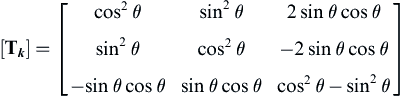 [6.31]
 [6.33]
 [6.34]
 [6.35]
 [6.36]
 [6.37]
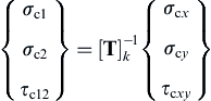 [6.38]


 [6.43]
 [6.44]
 [6.45]
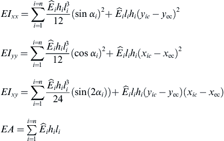 [6.46]
 [6.47]
 [6.48]
 [6.49]
 [6.50]
 [6.51]
 [6.52]
 [6.53]
 [6.54]


