
8
Design of generators for offshore wind turbines
Abstract
Although they are based on the same fundamental electromechanical principles, the design rotating electrical machines to convert mechanical to electrical power in wind turbines is different to that found in more conventional power plants. Because of the differences in the rest of the wind farm, the design priorities of generators for offshore wind tend to be different to those for onshore wind: there is an emphasis on high efficiency, higher power rating and high reliability. The search for a generator type that delivers lowest cost of energy continues, with a number of technologies in development.
Keywords
Asynchronous machine; Doubly fed induction generator; Generator; Offshore wind; Permanent magnet generator; Rotating electrical machines; Squirrel cage induction generator; Synchronous machine8.1. Introduction: key issues in generator design
The electrical generator plays a critical role in the wind turbine because of its electromechanical nature. The generator acts as an interface between the mechanical subsystems – such as the rotor and drive train upstream of the generator – and the electrical subsystems – such as the power converter and the grid. Despite being a relatively modest portion of the offshore wind farm cost, the electrical generator can have a significant influence on its cost of energy as the type and design of the generator influence turbine efficiency, operation and maintenance (O&M) costs and availability [1].
After discussing the role of the generator in wind turbines, and how the application of offshore wind turbines is different to that of conventional generation plants, this chapter will give a brief overview of electrical machines from a conceptual view point (Section 8.2), describe some of the practical engineering aspects of the generator (Section 8.3), before going on to describe the types of electrical generators that have been chosen for real offshore wind turbines and explaining the motivation for these choices (Section 8.4). At the end of the chapter, the authors will go on to survey some of the advanced types of generators that may be popular in the coming years (Section 8.5).
8.1.1. What is a generator and what should it do?
An electric generator is a device for generating electricity from a mechanical energy input. In the context of offshore wind turbines the mechanical energy is obtained by capturing the energy in the wind with a turbine rotor and – in some turbines – converting that high torque and low speed into lower torque and higher speed using a gearbox (or other torque–speed converter). In other cases, the mechanical energy may come from many different sources. In more conventional power plants the mechanical energy input comes from prime movers powered by combustion engines, steam turbines, hydro turbines and gas turbines.
Based on Faraday's law of electromagnetic induction, electrical energy is generated through the mechanical process of passing a conductor through a magnetic field. This process creates a potential difference (voltage) between the ends of the conductor. From Ohm's law, it is known that an electric current will flow when the ends of this conductor are connected to an electrical circuit with a resistance. The flow of current will interact with the magnetic field and act to produce a force resisting the motion of the conductor. In order to continue moving the conductor at the same speed, a mechanical force of the same magnitude must be provided and applied in the direction of movement. The result is that mechanical power (force × speed) is converted into electrical power (voltage × current).
An electrical generator performs this process of converting mechanical power into electrical power writ large. In doing so the generator produces torque (the result of force acting at some radius from the axis of the rotating machine) opposing the mechanical torque from the wind turbine rotor and drive train. From the electrical point of view, the generator is a voltage source (with some impedance) which depends on the type and design of the generator and on the operating conditions of the wind turbine and the generator.
In most electrical generators, it is convenient to induce electromotive force (emf) (and hence current) in stationary conductors, and hence they are located in a part of the machine which does not rotate (called the stator, as shown in Fig. 8.2(a)). The magnetic field is moved instead, and its source is mounted on a rotating part of the generator (called the rotor). The rotor and stator are separated by a clearance termed the ‘air gap’. Fig. 8.2(b) shows a generator and its rotor and stator.
In a synchronous generator the rotor magnetic field is produced either by using permanent magnets or else direct current is used to excite an electromagnet. As the excited rotor rotates it produces a rotating magnetic field in the air gap between the rotor and the stator. The stator contains a number of conductors that cut the magnetic field that is rotating in the air gap, in turn generating a current and hence electrical power output. Section 8.2 provides a more detailed explanation of the operation of the synchronous generator as well as detailing the operation of asynchronous generators.


8.1.2. What makes a good generator?
Depending on design requirements an offshore wind turbine generator will be considered good if it is:
• highly efficient, both at rated power and across the power curve,
• reliable, with a low failure rate and a short mean time to repair,
• cost-effective, both to purchase and to operate and maintain,
• lightweight, compact and easy to install,
• able to operate over a large speed and torque range.
As with many engineering systems, a number of these qualities complement one another and in some cases run counter to one another. For example, a more reliable generator may have lower maintenance costs but might be less efficient and more expensive to build. As a result of this, a balance must be struck to ensure a generator with the required qualities is chosen for a particular purpose. One approach for the turbine generator designer to balance these qualities and gauge the relative importance of them is to consider how the generator design affects the levelised cost of energy [1]. This approach will be used in Section 8.4.
Fig. 8.3 shows some of the large wind turbines which are currently in development or just starting to be manufactured. Generally, a good generator should be efficient, with as few losses as possible over a wide speed and torque range. Permanent magnet synchronous generators (PMGs) are usually better in this area than electrically excited machines as no current is needed to produce the rotor magnetic field and hence there are no copper losses on the generator rotor. Generators should also be reliablem with as few failure modes as possible and PMGs and squirrel cage induction machines show greater reliability due to their lack of slip rings and brushes, which are prone to failure and need regular servicing. However, this improved generator reliability has a consequence for the reliability of the power converter: there is a higher failure rate for the fully rated converters required for variable speed operation of PMGs and squirrel cage induction machines than for those used in doubly fed induction generators [2]. Onshore, failures to power converters tend not to lead to long downtime as they are relatively quick to repair. Offshore – where access to the turbine is more challenging and expensive – the consequence of even small failures can be costly. Manufacturing cost effectiveness and cost planning is also an important aspect for generator and wind turbine manufacturers. In this area PMGs are not as favourable as the electrically excited machines because the rare earth materials required for the permanent magnets are more expensive and cost volatile [3].

Figure 8.3 Drivetrain choice for some large wind turbines, specified by speed and torque conversion, generator type and rating of power converter [1].
8.1.3. What are the differences between generators in conventional power plants and those in wind turbines?
Wind turbine generators and generators from conventional power plants differ in a number of ways. The main reason for these differences is the source of the mechanical input to the generator. Generally speaking, the mechanical power of the prime mover is at a higher rotational speed for conventional power plants than in wind turbines. This means that if the generator is directly connected to the prime mover (‘direct drive’) then the generator in a conventional power plant can produce more power for the same generator torque rating. The corollary of this is that to produce the same amount of power, the direct drive wind turbine generator must have a higher torque and hence will be more expensive than would be the case in a conventional power plant. As conventional power plants tend to make use of a more energy-dense medium, the turbines tend to have power ratings of 102–103 MW, whereas offshore wind turbines have power ratings in the range 2–8 MW, with some design work at 10–20 MW. Each wind turbine generator will have a lower power rating and so will be cheaper, however the total cost of electrical generators for a 1000-MW wind farm will be higher than that for a 1000-MW conventional power plant as there are fewer generator units.
The generators in conventional plants tend to operate at a fixed speed and the mechanical input torque can be controlled relatively easily. Conventional plants tend to use synchronous generators which are usually directly connected to the grid. One result is that the rotational inertia of the turbine and generator naturally contributes to the stability of the electrical frequency of the electrical network. Because the excitation current can be varied, it is possible to control the power factor of the generator and provide or absorb reactive power as necessary. Although some earlier wind turbines were directly grid-connected, they used induction machines. This meant that the wind turbines were fixed speed rather than variable speed (the latter being preferable from a mechanical loading point of view) and that they consumed reactive power from the grid, this often having to be compensated for.
Another difference between conventional plants and the wind turbine is the location of the electrical generator. In conventional plants the generator is placed in well-controlled conditions, the generator can be easily accessed and the total generator mass is relatively unimportant. In wind turbines, the generator is almost always placed in a nacelle on top of the wind turbine tower. Obtaining the required amount of power for driving the generator requires large wind turbine rotor blades. Due to this large blade requirement, wind turbine generators are usually located on towers that can be more than 100 m above sea level. The fact that these generators are elevated to such heights means that mass can become a constraint as additional tonnes of material can affect the tower, foundation and installation costs.
8.1.4. What are the differences between onshore and offshore wind turbine generators and the challenges for offshore wind turbine generators?
Generators also differ in a number of ways when used in onshore and offshore wind applications. The main reasons for these differences are the accessibility problems related to being offshore, larger lifting equipment costs offshore and the ability to have larger blades offshore.
Offshore wind has a higher cost of energy than onshore wind, and one of the contributory factors to this is the higher operations and maintenance costs. Newer offshore wind farms also tend to be placed further offshore than the first wind farms of the 1990s and 2000s. Moving further offshore often means sites have higher mean wind speeds and are subject to higher mean wave heights. As maintenance and repair vessels have wind speed and wave height operational limits, sites further offshore are less accessible than near shore, and near-shore sites are less accessible than onshore. These offshore access problems are leading wind turbine manufacturers to develop different types of generators for the offshore market compared to the onshore market. Manufacturers are focusing on making offshore generators more reliable, introducing redundancy and extending time between services to ensure offshore generators do not have to be visited as often as onshore generators [4].
Another aspect influencing the design of offshore generators is the cost of replacing them when they fail. Cranes can be used onshore, but heavy lift vessels – usually rented on daily rates of over £100,000 per day – are required offshore [5]. As a means of overcoming this, manufacturers are aiming to make their offshore generators modular, to allow them to be repaired and replaced without, or with reduced, use of heavy lift vessels.
Generally, offshore wind turbines have larger rotor diameters than those onshore. Partly this is to mitigate the expense of offshore foundations and cabling by increasing the power rating of each turbine and increasing each turbine's annual energy production. Reducing the rotor power density also leads to larger swept areas – this helps improve the turbine's capacity factors and utilisation of the transmission cabling. One advantage of offshore wind turbines is that there tend to be fewer objections from the local community than for onshore wind turbines. These objections can be sensitive to hub height, blade length and blade noise. This relaxation tends to lead to longer blades offshore as can be seen in Fig. 8.4. This larger blade size allows for greater mechanical torque to be produced offshore, resulting in generators offshore having a higher rated power. This is evident in the portfolio of major manufacturers who offer 7- and 8-MW turbines with rotor diameters up to 154 m (Siemens D7) and 164 m (Vestas V164) offshore but the largest onshore turbine is rated at 7.5 MW and has a rotor diameter of 126 m (Enercon E−126).

8.2. Electrical generators: types and principles of operation
8.2.1. Types of electrical machines
Generators belong to a family of devices known as electrical machines, which share the same principles of operation. There are three types of electrical machines and wind turbines can contain all of these:
• Generators, rotating electrical machines which convert mechanical power into electrical power;
• Motors, rotating electrical machines which convert electrical power into mechanical power. These are often used in yaw drives and pitch actuators, and
• Transformers, stationary devices which convert from one voltage level to another voltage level. These are used to step up the voltage level from the wind turbine to medium voltage used in the wind farm electrical collection system.
Rotating electrical machines can perform the roles of either generator or motor depending on the way they are controlled, the electrical connection and the nature of the mechanical interface. Fig. 8.5 shows this. There are two major categories of rotating electrical machines, those that use/produce alternating currents (AC) and those that use/produce direct current (DC). In conventional power systems – which are based on AC motors and generators – the majority of generators are synchronous machines and most motors are asynchronous machines. In wind turbines both synchronous and asynchronous machines (also known as induction machines) are used as generators.
The machine described in Section 8.1.1 is a primitive synchronous machine. In the case of the synchronous generator the rotor rotates at the same speed as the electromagnetic flux waveform in the air gap of the machine. For the wind turbine rotor to have a variable speed, the electrical frequency of the machine must also be variable in nature and this means that the generator stator must be connected to a power converter to decouple it from the grid frequency. The synchronous machine is described in more detail in Section 8.2.3.

Although similar in construction to the synchronous machine, induction machines have a different principle of operation. In these machines, an alternating current is present on the rotor windings, giving rise to a rotor magnetic field which rotates at a speed slower or faster than the rotor. This field is either induced from the electromagnetic field on the stator (ie, squirrel cage induction generators) or else set up by a current from a static power converter connected to the rotor windings through brush gear and slip rings (ie, doubly fed induction generators). The principle of operation of these induction machines is explained in the Section 8.2.4.
8.2.2. Principles of electromagnetic conversion
There are two basic electromagnetic phenomena at play in rotating electrical machines:
• When a conductor moves relative to magnetic field, a potential difference is induced in the conductor. This was described in Section 8.1.1 and is shown in Fig. 8.1. If the conductor is connected to a closed circuit a current will flow in the direction given by Fleming's right-hand rule (hold the right hand so that the thumb, first finger and second finger are all perpendicular to one another. The thumb is in the direction of motion; the first finger is in the direction of the field; the second finger is in the direction of the induced current).
• When a current-carrying conductor is present in a magnetic field it will experience a mechanical force. This is shown in Fig. 8.6. The conductor will experience a force in the direction given by Fleming's left-hand rule (hold the left hand so that the thumb, first finger and second finger are all perpendicular to one another. The thumb is in the direction of the force; the first finger is in the direction of the field; the second finger is in the direction of the induced current).
![]() [8.1]
[8.1]
where B is the flux density (in T), l is the length of the conductor in the magnetic field (units of m) and v is the linear speed (in m/s). In the case of electrical generators, the linear velocity is the product of a rotational speed of a magnetic field at a radius. Good generators are able to produce significant air gap flux densities. Total induced voltage can be found by summing all the individual voltages from all of the conductors which are connected in series in a phase. Induced voltage is sometimes described as the emf.

In rotating electrical machines, one often thinks of coils (a combination of pairs of antiparallel conductors distributed around the stator of the machine so that they experience flux density of the same magnitude but opposing sign). For a coil, Faraday's law states that the induced voltage in a coil is proportional to the negative rate of change of magnetic flux. This is given in Eq. [8.2],
![]() [8.2]
[8.2]
where N is the number of turns in a coil, Φ is the magnetic flux (units Wb) and λ is the flux linkage (units Wb-turns). Flux density, B, is the magnetic flux per unit area (B = Φ/A) and flux linkage is the product of the magnetic flux passing perpendicularly through the coil and the area of the coil.
To find the force, f, (units N), applied to the current-carrying conductor in Fig. 8.6, one can use Eq. [8.3],
![]() [8.3]
[8.3]
where I is the current (in units of A). Going from the forces on individual conductors to the torque developed in an electrical machine requires the individual forces to be summed, and the result to be multiplied by the radius.
8.2.3. Synchronous machines
In synchronous machines, the rotor carries the field winding with the armature winding mounted on the stator. Fig. 8.7 show the rotors of three different types of synchronous machines: a cylindrical rotor, a salient pole rotor and a rotor with surface-mounted permanents. Cylindrical rotors tend to be used in higher-speed machines in conventional power plants. Salient pole rotors are often used in larger, lower-speed machines in applications such as hydro generators and some direct-drive wind turbines. The first two types require a DC supply to the rotor which can be provided through brush gear and slip rings or through brushless excitation (basically another electrical machine or set of machines mounted on the shaft). Most offshore wind turbines that have a synchronous generator use permanent magnet excitation on the rotor.
8.2.3.1. Principle of operation at no load
Fig. 8.8 shows a rotor with two poles (one pole pair). Each pole is a piece of steel with a coil wrapped around it with N number of turns. The coil is excited with a field current, If. The product, NIf is the magnetomotive force (MMF). The strength of the flux density which is produced in the air gap depends on this MMF as well as the length of the air gap, the choice of materials used in the generator rotor and stator and the dimensions of the parts of the machine which conduct the magnetic flux. In the case of this DC excited synchronous machine, the flux density can be controlled by varying If; for PM machines the MMF is fixed for a given design.

Figure 8.7 Different rotors used in synchronous generators: (a) cylindrical, (b) salient pole, (c) surface-mounted permanent magnet.
In the simple machine shown in Fig. 8.8, there are three phases: a, b and c. These are shown by the coils aa′, bb′ and cc′ (where a′ means that the conductors are in the opposite direction to the conductors a). These coils are distributed by 120 degree or  radians relative to one another. As the rotor rotates, flux linking each phase depends on the rotor angle, θ. For a given rotational speed, ω, this angle is given by θ = ωt. The starting position of the rotor in Fig. 8.8 means that coil aa′ sees 0 flux linking the coil. Looking to Fig. 8.8(b), it can be seen that this flux linkage increases to a maximum when the rotor turns by 90 degree or
  radians; as the rotor angle θ increases further, the flux linkage drops until it is 0 when the rotor angle is 180 degree or π radians. Further rotation means that the flux linkage is negative, reaching a minimum at 270 degree or
  radians and then returning to 0 when the rotor angle is 360 degree or 2π radians. It can be shown through relatively simple trigonometry that the flux linkage waveforms take on a sine function. The same flux linkage waveforms are applicable for the two other phases, except they are displaced by 120 degree or radians relative to one another.

From Eq. [8.2], it can be seen that the induced voltage waveforms are found by differentiating the flux linkage functions. This gives rise to the waveforms in Fig. 8.8(c). The magnitude of the induced voltage depends on the peak flux per pole (and hence is proportional to the field current), the number of turns in a coil and also the rotational speed. It can be seen that some of these variables are fixed at the design stage (for example, number of turns), some may depend on the operational conditions (for example, rotational speed) and some can be controlled (for example, field current). For a permanent magnet generator, once the generator is designed the magnetic flux is fixed as the MMF cannot be controlled. This means that the induced voltage is speed dependent,
![]() [8.4]
[8.4]
The frequency of the induced voltage is dependent on the rotational speed and the number of pole pairs, p. In the case of the machine in Fig. 8.8, there are two poles and hence one pole pair (p = 1). Most wind turbine generators have p > 1, and it is not uncommon for medium-speed permanent magnet generators to have p > 40 and slower directly driven permanent magnet generators to have p > 80. The frequency is given as
![]() [8.5]
[8.5]
In this case ωm is the mechanical rotational speed (rad/s). A useful concept can be the equivalent electrical angular frequency, which is defined as ωe = 2πf = pωm.
8.2.3.2. Synchronous machine equivalent circuit
Despite being an electromechanical device, it is possible to produce an equivalent circuit diagram of the synchronous machine. This can be useful for understanding the machine's capabilities and limits, as well as relating to power engineering modelling (either for designing and modelling power converters, or understanding the role of these machines in the power system more generally). The machines are normally designed to have three balanced and identical phases. As such it is sufficient to draw the equivalent circuit for any one of the three phases.
So far the discussion of magnetic flux has centred on the flux produced by the rotor field, Φf. As armature current, Ia, starts to flow in the armature winding (the electrical windings on the stator), another magnetic flux is produced, Φa. Part of this flux links with the stator winding only and is known as the leakage flux, Φal. Another part of the armature flux links with the rotor – this is known as the armature reactance flux, Φar. As these fluxes are dependent on the magnitude of the armature current and lead to a voltage drop, they can be represented by reactances Xal and Xar in Fig. 8.9(a). These can be combined into the synchronous reactance, Xs, shown in Fig. 8.9(b). There is a further voltage drop due to the resistance of the stator winding Ra. Generally Xs >> Ra and in some cases the resistance can be neglected [6].
8.2.3.3. Synchronous machine phasor diagram
A phasor diagram shows the relationship between voltages and currents. One such diagram is shown in Fig. 8.10 for a non-salient pole synchronous generator. The terminal voltage, Vt, is taken as the reference phasor. The equation for the phasor diagram is,
![]() [8.6]
[8.6]
where φ is the phase angle between the terminal voltage and the armature current and δ is the power angle (sometimes referred to as the torque angle). This reveals that for a given induced emf, increasing the armature current will lead to a drop in terminal voltage. As the current increases, the power angle will increase up to a certain limit.


8.2.3.4. Synchronous machine power and torque characteristics
If the armature resistance is neglected then it can be shown that for a three-phase cylindrical pole or surface-mounted permanent magnet machine that the power and torque are given by Eqs [8.7] and [8.8] [6].
![]() [8.7]
[8.7]
![]() [8.8]
[8.8]
where ω is the rotational speed in rad/s. A theoretical limit of δ = 90 degree = radians will give the peak power and torque. It can be appreciated that machines with higher power ratings tend to have higher voltage ratings or more phases.
For machines with saliency – for example the machine in Fig. 8.7(b) and permanent magnet machines with buried magnets – the power and torque characteristics are modified due to a component of reluctance torque. For more details the reader is referred to [6].
In a variable speed application, such as a wind turbine, Eq. [8.4] shows that the induced emf is dependent on the rotor speed. Reactances are also dependent on electrical frequency (X = ωeL, where L is an inductance). This means that the power and torque capability depend on the operational speed of the turbine. In order for the synchronous machine to work at variable speed, the terminals of the generator are connected to a power converter. This converter can effectively set the generator's terminal voltage, Vt, hence controlling the power and torque of the generator.
Fig. 8.11 shows the torque speed plane for a wind turbine [7]. The axes are expressed in terms of wind turbine rotor torque (TWT = kTgen, where k is the gearbox ratio and Tgen is the generator torque) and rotational speed (ωWT = ωm/k). A family of curves is defined for constant wind speed and another family represents the operation at various constant performance coefficients of the wind turbine rotor. The shape of these curves depends on the cp–λ characteristics and is arbitrary for this example. The filled circles represent the points of peak aerodynamic performance at different wind speeds. Because the synchronous machine naturally has a fixed torque speed characteristic, the generator synchronous speed must be varied in order to achieve these points. This is achieved by varying the electrical frequency at the generator terminals. In this example a power converter is used to vary the frequency in the range flow ≤ f ≤ fhigh.

8.2.4. Asynchronous machines
8.2.4.1. Components and principle of operation
Three-phase induction machines are the machines most commonly encountered in industry [8]. Fig. 8.12 shows the cross-section of an induction machine. The machine consists of a stationary stator, an air gap and a rotating rotor. The stator is similar to that in the synchronous machine. The rotor is different to the synchronous machine: alternating current instead of direct current excites the rotor. This alternating current can be induced on the rotor by the three-phase current on the stator or it can be provided via brush gear and slip rings. The rotor can consist of a number of short-circuited copper bars (known as a squirrel cage rotor) or a wound rotor which consists of three windings similar to the stator.
Faraday's law is again the underlying principle of the operation of an induction machine. The ladder example is a useful way of demonstrating how an induction generator works. Fig. 8.13 shows a ladder shape made from an electrically conducting material. The rungs of the ladder are held in place and short-circuited by two bars, X and Y. When a magnet is moved relative to the rungs, a magnetic flux cuts the conducting ladder rungs. Based on Faraday's law, a voltage is induced in the ladder because it is made of a conducting material. The induced voltage produces a current that flows through the rung that the magnet is passing over and into the short-circuiting bar before flowing back through the other rungs. This creates a set of poles, the closest of which wants to align with the permanent magnet; the ladder will experience a mechanical force trying to move it to the right. As the ladder moves to the right its conducting rungs will be cut less rapidly by the magnetic field than if it was stationary, reducing the induced voltage and consequently the current and mechanical force. The voltage, current and mechanical force would drop to zero if the ladder was moving at the same speed as the magnet (synchronous speed) due to the magnetic field not being cut by the conducting rungs on the ladder. The magnet can conceptually be replaced by an electromagnet that moves at the same speed. A further conceptual development is to recognise that a moving MMF waveform can be produced by exciting distributed coils with a time-varying current.

If the ladder described in the previous paragraphs was rolled into a circle as shown in Fig. 8.14 it would function exactly as a squirrel cage rotor in a rotary induction generator. In a squirrel cage induction machine a voltage is induced in the bars of the squirrel cage making it move (rotate) as the ladder in the previous example does.
When the squirrel cage is rotating at the same speed as the flux in the air gap (synchronous speed) there is no voltage induced or force applied to the rotor. When there is a difference in the angular velocity of the squirrel cage rotor and the velocity of the flux in the air gap, this is known as slip. Slip, s, is expressed as a percentage of the speed of the flux in the air gap (synchronous speed) and is given by

Figure 8.13 Ladder model of an induction machine. (a) Electrically conducting rungs and connecting bars; (b) magnet moves with velocity v; (c) inducing current in rungs; (d) produces force on rungs; (e) magnet can be replaced by moving electromagnet; (f) the moving MMF can also be produced by exciting electromagnets with a time-varying current.
![]() [8.9]
[8.9]
where ωs is the synchronous speed and ωr is the rotor speed (ω is in rad/s, n is in rpm). The synchronous speed is the same rotational speed as the synchronous machine ωm, as described in Eq. [8.5]. Most induction motors are directly connected to the grid and so common synchronous speeds for a 50-Hz grid are 3000 rpm (p = 1, two poles), 1500 rpm (p = 2, four poles) and 1000 rpm (p = 3, six poles). Slip allows a variation from the synchronous speed. Larger values of slip mean that a greater percentage of the rated power is lost on the rotor – leading to heat generation – and so larger machines tend to have smaller values of slip.
The basic induction machine starts to work as a generator when the rotor speed exceeds the synchronous speed. This will be examined in more detail in the next subsection.
8.2.4.2. Equivalent circuit and torque speed diagrams
For the purpose of network simulation induction, generators can also be represented by an equivalent circuit. The equivalent circuit for an induction generator is similar to that of a transformer and is shown in Fig. 8.15.
In Fig. 8.15, V1 is the per-phase terminal voltage, R1 is the per-phase stator winding resistance, X1 is the per-phase stator winding leakage reactance, E1 is the per-phase induced voltage in the stator winding, Xm is the per-phase stator magnetizing reactance, Rc is the per-phase stator core loss resistance, E2 is the per-phase induced voltage in the rotor at standstill, R2 is the per-phase rotor circuit resistance and X2 is the per-phase rotor leakage reactance. Rotor circuit parameters are referred to the stator using the ratio of turns on the stator and rotor, a = N1/N2.
Fig. 8.16 shows a torque speed diagram for an induction machine (for convenience, T is drawn as positive for generating action). The torque speed curve is given by Eq. [8.10] from [6],
![]() [8.10]
[8.10]


It can be seen that as the slip approaches zero (s→0, ω→ωs) the torque falls to 0. The induction machine has a linear torque speed relationship when operating close to the synchronous speed. The highest torque, Tmax, can be changed by the generator designer by adjusting the resistance of the rotor. Adjusting the rotor resistance changes the shape of the torque–speed curve.
8.2.4.3. Variable speed operation
In the early grid-connected wind turbines, squirrel cage induction generators were used and directly connected to the grid. The turbines were essentially fixed speed, but the generator slip allowed some compliancy giving less severe loading than was the case for synchronous machines directly connected to the grid.
The first step to introducing variable-speed operation was to use squirrel cage induction machines with two sets of windings that could be changed between; these gave rise to two different synchronous speeds and gave a crude version of variable-speed operation. Changing between the generator windings can be electrically and mechanically stressful and is not often used anymore.
A further development is to use a wound rotor with variable rotor resistors. By changing the shape of the torque–speed curve, increasing the rotor resistance can give greater slip at lower torques. This can be achieved with external resistors connected to the wound rotor with brush gear and slip rings, however this can be prone to failure. Some machines used resistors mounted onto the machine rotor with an optical communication link to signal when to switch resistance. Although able to give variable-speed operation, this is at the expense of electrical losses on the rotor. One of the next developments was to identify how to usefully extract this slip energy.
In a doubly fed induction generator (DFIG) there are windings that allow for power take off on both the stator and the rotor, as shown in Fig. 8.17. The stator winding is directly connected to the grid and the rotor winding is connected to a power converter (via slip rings and brushes) before reaching the grid. The use of the power converter allows the rotor currents to be adjusted so that the frequency and direction can vary [10]. At synchronous speed, the rotor can be fed with DC and will act as if it were a synchronous machine. In subsynchronous operation, power is fed to the rotor from the grid. If the synchronous speed is 1500 rpm and the rotor speed is 1200 rpm, this implies currents of a frequency that produce a magnetic field that moves relative to the rotor at a speed of 300 rpm. In supersynchronous operation, power is taken from the rotor and fed to the grid. In the same example, a rotor speed of 1800 rpm would need currents of a frequency that produce a field that moves relative to the rotor at a speed of −300 rpm. The DFIG configuration allows for the rotor speed to vary around the synchronous speed by a greater amount than the squirrel cage induction generator with no power converter and also allows for the use of less power electronics than a fully rated converter. This is an advantage as power converters reduce the reliability of the power train. However, some of the reliability improvements over the standard induction generators are cancelled out due to the use of slip rings and brushes with the DFIG [2].


Figure 8.18 Varying an induction machine's torque speed: (a) by varying terminal voltage; (b) by varying frequency.
Fully rated converters can be used with squirrel cage induction machines to give variable-speed operation. Fig. 8.18 shows the effect on the torque speed characteristic of a machine when varying terminal voltage and when varying the frequency. These can be used in combination to meet the torque speed characteristics needed for a variable-speed wind turbine.
8.3. Practical design and manufacture of electrical generators
In the design and manufacturing of generators, designers and manufacturers must work with a number of components and specialist materials. As described in Section 8.2, a generator consists of a rotor and a stator with bearings as the mechanical interface between them (and possibly brush gear and slip rings acting as part of the electrical interface). Electrically these machines have windings, different types of insulation and electrical terminals. From a magnetic point of view the design and manufacture of flux-conducting material such as steel laminations is important and the specification of any permanent magnets has an important influence on cost and losses. As well as these items there are requirements for auxiliary subsystems such as forced air- or liquid-coolers, and mechanical parts that are able to meet load requirements and provide protection for the generator. This section gives a brief overview of generator components and their design.
8.3.1. Rotor
The rotor in a generator is primarily used to create a magnetic flux in the air gap but it can be used for power take off, as in a DFIG. Ordinarily, the rotor is placed inside the stator allowing for a short conduction cooling path from the hotter stator to ambient. In some cases – such as the Siemens direct-drive wind turbines – an outer rotor is used [11]. This allows for a slightly larger air gap diameter for the same outer diameter and hence better torque for the same force production.
The manufacturing process of a generator rotor depends on the type of generator it is to be used in. Two of the most common types of rotors in wind energy are the permanent magnet rotor in a permanent magnet synchronous generator and the wound rotor in a DFIG.
As the name suggests the permanent magnet rotor is manufactured using permanent magnets, such as neodymium (NdFeB). These have the advantages of having high maximum energy product, meaning that they can produce a strong flux density using a relatively small mass of material. They have a high coercivity and remnant flux density but a relatively modest relative permeability see, e.g., [12]. This means that they are able to resist demagnetisation but that the magnets themselves are not very good at ‘conducting’ magnetic flux and care must be taken to design the magnets to get best use of the expensive magnet material. Fig. 8.7(c) shows these magnets mounted onto the surface of the rotor. Even though they appear to be salient pole machines, this low permeability means that the air gap reluctance is fairly constant as one travels circumferentially around the air gap radius. As such they can be treated as non-salient machines. Some machines, using less energy-dense permanent magnetic materials – such as Ferrite magnets – need to use flux concentration techniques, burying magnets between steel poles. In this case these machines are salient in nature.
Sometimes the magnets on the rotor are skewed relative to the teeth and slots on the stator. This helps reduce the effect of cogging torque. This effect, whereby the rotor magnets favour being in alignment with the teeth on the stator can add an unwanted ripple onto the machine torque and mean that there is a minimum starting torque to get the generator to rotate. Skewing means that the circumferential position of the magnet pole varies as one moves axially from one end of the machine to the other. Other techniques for reducing cogging torque also exist, including shaping the magnets in the radial, axial and circumferential dimensions.
The wound rotor in the DFIG is manufactured using copper wire wound around steel teeth in a cylindrical core. In a squirrel cage induction machine, electrically conducting bars are embedded into the same types of slots in the rotor steel. The core of the rotor is made from steel laminations. In a DFIG the shaft of the rotor is then connected to slip rings and brushes.
8.3.2. Air gap
Termed the ‘air gap’, the gap between the rotor and stator has two interpretations. The first is the physical distance between the rotor and stator surfaces. This must have a non-zero value at all points around the air gap radius, at all points in time – otherwise physical damage would occur as the rotor and stator come into contact. The gap must be dimensioned to allow for manufacturing tolerances, rotor and stator eccentricity, deformation under loads, as well as the impact of loads from the wind turbine rotor itself. A starting point for design of larger, direct-drive machines is that the air gap, g, is often dimensioned according to the rule of thumb g = dg/1000, where dg is the diameter at the midpoint of the air gap. Hence a 5-m diameter machine would have a 5-mm air gap.
From a magnetic perspective, the air gap is important as it leads to reluctance which reduces the flux per pole. The magnetic or effective air gap is the notional dimension of air that gives rise to the same magnetic reluctance as the real machine. The effect of slotting (which tends to increase reluctance) can be factored in. The biggest difference between ‘real’ and ‘effective’ air gap values is found in surface-mounted magnet machines. Here the height of the magnet – a material which has almost the same permeability as air – is also included in the air gap. So, a 15-mm-high magnet and a physical air gap dimension of 5 mm leads to an effective magnetic air gap of 20 mm (if we neglect the effect of slotting). Reducing the physical air gap from 5 to 4 mm (−20%) only reduces the magnetic air gap from 20 to 19 mm, and hence reluctance reduces by only 5%.
8.3.3. Stator
The stator is the part of the generator that remains stationary while the rotor rotates relative to it. It consists of conductors which are normally embedded into slots in the surface of the stator laminations. These conductors in the stator are usually made of copper windings but can be made from aluminium. Insulation is used to prevent short circuits between neighbouring conductors, between the conductors and the steel laminations and also between one phase and another. Insulation is normally further improved by using a technique called vacuum pressure impregnation, whereby the stator is dipped in epoxy resin and cured in a vacuum vessel.
The steel laminations are thin sections coated with a thin layer of insulating material. Laminations are used instead of solid steel because they reduce eddy current losses. Special electrical steel with silicon content is used which is designed to reduce hysteresis losses.
The generator frame and housing provide the structural support and protection for the internal workings of the generator. Heat can build up in a generator during the generation process leading to losses in efficiency, so cooling systems are required. Two of the basic types of cooling systems in wind energy generators are forced air and liquid cooling [13].
8.3.4. Structural integrity
High-speed machines can be thought of as standalone machines, relatively independent of the wind turbine. The major challenges from a mechanical point of view are the relatively high rotational speeds, the input loads from the high-speed shaft of the gearbox and misalignment [14].
Low-speed machines in direct-drive wind turbines are much larger and so tend to be significantly integrated into the wind turbine structure. As the torque rating increases, so too does the air gap diameter and axial length. Due to the magnetic forces of attraction (between the ferromagnetic parts of the rotor and the stator), there tend to be large forces trying to close the air gap. This, along with the torque loading, can mean that these generators need considerable structures in order to give sufficient stiffness [13]. For large direct-drive machines, this mass can dominate the mass of the material used to produce electrical power [15].
8.3.5. Generator losses
The major sources of losses in AC machines are copper losses and iron losses. There are also minor loss mechanisms due to bearing friction and windage (aerodynamic drag on the rotor surface).
Copper losses result from current flowing through the resistance of any windings (field or armature). This can be reduced by reducing resistance, either by increasing the cross-sectional area of conductors (generally increases the size of the machine), lowering the winding temperature (reduces the resistivity) or using materials which have lower resistivity. Copper is usually used as the conductor material and increasing current densities can be achieved – without significant additional losses – with improving cooling systems.
Iron loss is an important loss component in the components that conduct flux, which changes with time. They are sometimes described as ‘core losses’. The two loss mechanisms are hysteresis and eddy current losses. Both of these increase with increasing flux density in the teeth and back iron. Hysteresis losses are proportional to the electrical frequency and the eddy current losses are proportional to the square of the electrical frequency. The electrical steel used in the stator and rotor of induction machines is affected, whereas the rotors of synchronous machines are less affected as the main field is stationary relative to the rotor.
8.4. Selection of generators for offshore wind turbines
The following section provides examples of the generator types used in some of the more popular offshore wind turbines currently installed. The number of different generator types used highlights the variety in modern offshore wind turbine drivetrain configurations.
8.4.1. Siemens SWT 2.3 MW: SCIG
The Siemens SWT 2.3 uses a squirrel cage induction generator (SCIG), as shown in Fig. 8.19. It has a rated power of 2.3 MW and an output voltage of 690 V. It is cooled through an integrated heat exchanger and a separate thermostat-controlled ventilation arrangement that Siemens claim allows for cooler operation temperatures providing longer lifetime to the winding insulation [16].

No slip ring or brushes are required for this generator type because the squirrel cage is excited through electromagnetic induction. This allows for increased reliability because slip rings and brushes make up ∼50% of the overall generator failure rate [2]. Unlike PMGs, the SCIG does not require any rare earth materials in its manufacture. This is advantageous for manufacturers as it allows for better cost planning. It is notable that Vestas also opted for the SCIG in the second version of their V112 3.0 MW [17] rather than the PMG as used in the first version of their V112 3.0 MW [18].
8.4.2. Vestas V90: DFIG
The generator in a Vestas V90 is a doubly fed induction generator, as shown in Fig. 8.17. The V90 is available with generators rated at 1.8, 2 and 3 MW. The 3-MW generator has an output voltage of 1000 V. The generator has four poles and is liquid-cooled.
Slip rings and brushes are required for this generator type for power take off. The inclusion of these slip rings and brushes decreases reliability in comparison to the PMG [2], however a DFIG is cheaper than a PMG by up to ∼40% [19]. Like the SCIG and unlike PMGs, the DFIG does not require any rare earth materials in its manufacture. The use of the partially rated power converters with the DFIG allows for compliance to many grid codes, however the DFIG is not completely decoupled from the grid as in the PMG or SCIG, which both use fully rated converters.
8.4.3. Areva M5000: medium-speed PMG
The generator in an Areva M5000 is a medium-speed permanent magnet generator (PMG), as shown in Fig. 8.20. It has a rated power of 5 MW and an output voltage of 3.3 kV. Unlike the machines in the previous turbines it is a synchronous machine, instead of an induction machine. As it is a permanent magnet generator no brushes or slip rings are required to excite the rotor and power take off occurs at the stator.
As the input to the generator is from a single-stage gearbox the generator has a lower speed range than the previous turbine types, this means higher torque and a larger generator with more windings and insulation. As a result of these extra failure modes it is expected that lower-speed generators will have more winding failures than the high-speed generators in the previous two turbines but less than in an equivalent direct-drive generator [20].

The single rotor main bearing, single-stage planetary gearbox and the generator are packaged together in a compact single cast structure leading to a relatively lightweight solution.
8.4.4. Siemens SWT 6 MW: direct-drive PMG
The generator in a Siemens SWT 6 MW is a direct-drive PMG, as shown in Fig. 8.21. It has a rated power of 6 MW and an output voltage of 690 V. Like the Areva turbine, it is a synchronous machine and as it is a permanent magnet generator no brushes or slip rings are required to excite the rotor. As the input to the generator comes directly from the rotor it is a low-speed high-torque input. As the generator is direct drive it has a larger size, with an outer diameter of 6.5 m [11]. Located upwind of the tower, just behind the wind turbine rotor, these generators include structural elements to transmit loads from the wind turbine rotor back through to the turbine, as well as an access channel to get into the wind turbine hub.
8.4.5. Case study of generator selection
The following section shows a case study based on results from [2] [19], and [20] in which two turbine types are compared. One of the turbine types has a DFIG and the other has a PMG, both are compared based on cost of energy (CoE) and the results are shown in Section 8.4.5.6. The results that are compared in the following sections are based on operational data from modern multi-megawatt offshore wind turbines. The following sections show availability and operation and maintenance (O&M) cost for sites from 10 to 100 km offshore. The CoE comparison for both turbine types is carried out for a site located 40 km offshore as in [19].

8.4.5.1. Cost of energy
For the purpose of this case study, the cost of energy has been calculated using assumptions as used in the Crown Estate's ‘Offshore Wind Cost Reduction’ study [4]. Eq. [8.11] shows how the CoE is calculated [21],
![]() [8.11]
[8.11]
Capital costs include the cost of consenting/development, foundations, turbines, array cables, installation, decommissioning, insurance and project management. In this comparison the values for each of these figures, except for turbine costs, are the same and come from [4], turbine costs differ because of generator and converter costs and come from [20]. The fixed charge rate is defined so as to express the initial capital cost (and implied financing costs) fairly to a per-year basis. Annual operating costs consist of operation and maintenance costs, insurance costs, transmission charges and seabed rent. Each of these values are the same for both turbines and come from [4], except for O&M costs, which differ for the two turbine types and come from [20]. Annual energy production is different for the two turbine types as the turbines have different efficiencies and availability; in this case the data come from [20].
8.4.5.2. Generator costs
Fig. 8.22 shows the different manufacturing costs of a PMG and a DFIG with the same rated power. Both turbine types have other components that differ, such as converters, so Fig. 8.17 also shows the difference in cost for this when they are used with both generator types.

Figure 8.22 Cost comparison of PMG versus DFIG [20].
8.4.5.3. Efficiency and losses
Fig. 8.23 shows the electrical power curves for a DFIG turbine type and a PMG turbine type of the same rated power. The difference in power curve highlights the greater efficiency of the PMG due to the lack of copper losses on the generator rotor.
8.4.5.4. Availability
The availability of a turbine using a PMG and the availability of a turbine using a DFIG are seen in Fig. 8.24. These availability figures are based on a hypothetical offshore wind farm of 100 turbines located 10, 50 and 100 km offshore. The difference is driven by the failure rates and downtimes of both generator types and the different converters required for them to operate.

Figure 8.23 Normalised power curves for PMG and DFIG [20].

Figure 8.24 Availability of PMG and DFIG turbine types at different sites [20].
8.4.5.5. O&M costs
The O&M costs of a turbine using a PMG and a turbine using a DFIG can be seen in Fig. 8.25. Like availability, these O&M costs are based on a hypothetical offshore wind farm of 100 turbines located 10, 50 and 100 km offshore. The difference is driven by the failure rates, downtimes, repair costs, vessel costs and staff cost of both generator types and the different converters required for them to operate. Fig. 8.25 also shows the O&M cost when the cost of lost production is also included.
8.4.5.6. Analysis
The CoE comparison for the DFIG and PMG turbine type for a hypothetical 100 turbine wind farm located 40 km offshore can be seen in Fig. 8.26. The DFIG turbine has an overall CoE of £103.43/MWh and the PMG turbine type has an overall CoE of £101.23/MWh. As mentioned in Section 8.4.5.1 it is assumed that certain parts of the capital cost and operating cost remain the same for both turbine types. The drivers for the £2.20/MWh difference between the two turbine types are the variance in turbine cost, O&M cost and energy production. It is worth noting that the turbine cost and O&M cost figures in this analysis are based on cost data from a manufacturer and O&M provider so profit margins are not considered. These profit margins would drive up the CoE for operators. To put this cost/MWh difference into perspective, an offshore wind farm of 100 turbines, each producing 12,961 MWh [22] annually for a 20-year lifetime will see a cost difference of around £50 million pounds between the two turbine types, in favour of the permanent magnet generator over the lifetime of the wind farm.
Similar analysis but for medium-speed and low-speed permanent magnet generators tends to show that the cost of energy is even further reduced relative to these high-speed gearbox-driven generators [20].

Figure 8.25 O&M costs of PMG and DFIG turbine types at different sites [20].

8.5. Future trends in offshore wind turbine generators
8.5.1. Future challenges
As wind turbines get larger and move further offshore a number of challenges exist in all areas of the wind turbine and the generator is no exception to this. Larger generators located further offshore will face challenges when it comes to increased costs, reliability, accessibility and growing magnitude of loads.
As generator sizes increase, the cost of materials used in generator construction will naturally increase, however the big challenge in this area will come from the larger generators requiring more rare earth material for their permanent magnets. Rare earth materials used in permanent magnets – such as Dysprosium – are in short supply and are readily mined in only a few countries. This allows the supply and hence price to be manipulated. Price volatility – which generator manufacturers try to avoid – represents a risk which turbine designers would prefer to avoid.
Reliability of generators becomes even more important as turbines move further offshore and access becomes more challenging. Figs 8.24 and 8.25 show how the same technologies at different distances have lower availability and increased O&M costs as the distance to shore increases. This implies that future generators need to have lower failure rates and that the time and cost of repair need to be reduced.
One way to reduce the cost of energy for offshore wind farms is to increase the power rating and rotor diameter size. Assuming the same tip speed limit (eg, 90 m/s) and rated power per swept area (eg, 350 W/m2) figures, one can find that the rated torque grows from 3.75 MNm for a 5-MW turbine to 30.0 MNm for a 20-MW turbine. Especially for direct drive machines, this eightfold increase in torque for a fourfold increase in power means that – unless different technologies are used – the cost and size increase in the generator will rapidly outpace improvements in energy capture.
8.5.2. Developing existing generator technologies
As a means of overcoming some of the future generator challenges, new technologies are being developed. Wind generator researchers, designers and manufacturers are investigating and developing generator technologies, like brushless DFIG generators and air-cored PM machines, as well as adapting current technologies to make them more maintainable and reliable.
Brushless DFIGs are of interest to the wind energy industry because they would remove the brush and slip ring failure mode while keeping the lower failure rate of the partially rated converters [23]. The brushless DFIG operates through the use of a second stator winding – often termed the control winding – which fulfils the role of the brush gear and slip rings. The two stator windings are housed within the same generator frame but no direct coupling occurs between them.
Air-cored permanent magnet machines use air-cored windings in the stator of the machine. This allows for the elimination of ferromagnetic material in the stator which leads to the elimination of the force between rotor and stator described in Section 8.3.4. This in turn leads to advantages such as weight saving of up to 30–50%, making stator repairs easier and eliminating cogging torque [24].
As a means of making generators more maintainable and reliable, researchers and designers are designing for maintainability and fault tolerance. Generators and wind turbines that include modularity and redundancy are now being seen in academia and industry [25]. Like all reliability-related issues the business case for modularity and redundancy greatly improves as turbines move further offshore. Modularity allows for a failed module of the generator to be changed without requiring the replacement of the full generator. As well as the obvious cost advantage of replacing a module instead of a full unit, there are also huge advantages in the cost savings from vessel hire due to a module not requiring heavy lift vessels that may have long waiting times and have a day rate of over £100,000 [5]. Redundancy allows for generators to continue producing energy at a full or partial percent of the rated power even after a failure occurs. Although capital costs are usually higher due to the duplication of parts of the generator or the full generator, recent studies have shown that O&M savings may justify the higher capital costs [26].
8.5.3. Developing more radical generator technologies
Along with the conventional and emerging generators discussed above, a number of other generator technologies exist or have potential to be used in wind energy in the future. Technologies such as high-temperature superconducting generators and synchronous reluctance machines are being researched [27].
High-temperature superconducting machines encountered in the literature are both synchronous and asynchronous. Superconducting machines replace some of the materials used in conventional generators with superconducting materials. Superconductors offer greater efficiency across all loads due to having no DC resistance. They also allow for far stronger magnetic fields to be produced in comparison to conventional generators. This leads to higher torque density and reduced size, attractive qualities especially for direct-drive turbines. One significant challenge is that the machines have to be cryogenically cooled to around 50 K. The reliability and maintenance intervals of these cryostats and generators is one of the biggest hurdles: it can take more than a day to cool a generator to its operating temperature [27].
Synchronous reluctance machines are another form of electrical machine that are known for their low cost as they avoid the use of permanent magnets. The synchronous reluctance machine makes use of the effect of saliency, the component of torque which is different between cylindrical and salient pole synchronous machines. The lack of brush gear slip rings is attractive and a few authors have started to look at these machines in some detail [28].
8.5.4. Generators for use with advanced torque/speed conversion
Except for direct-drive wind turbines, torque and speed have been traditionally converted using a mechanical gearbox. Due to a high gearbox failure rate [29] and high direct-drive generator failure rates [30] alternative torque speed conversions for wind turbines have been investigated. These alternative methods include hydraulic and electromagnetic conversion and enable the use of other types of generators.
The hydraulic torque/speed converter in a wind turbine uses a hydraulic pump, accumulator and motor, which drives a generator at a constant speed. It is the modulation of these hydraulic units that gives the turbine its variable speed capability, rather than the control of the generator. The fact that the generator can be driven at a constant speed allows for the use of a constant-speed synchronous generator. In one of the wind turbine types that uses hydraulic torque/speed conversion, brushless synchronous generators are used (in this configuration, an auxiliary electrical machine is mounted on the shaft and is used to generate and regulate the DC) [31].
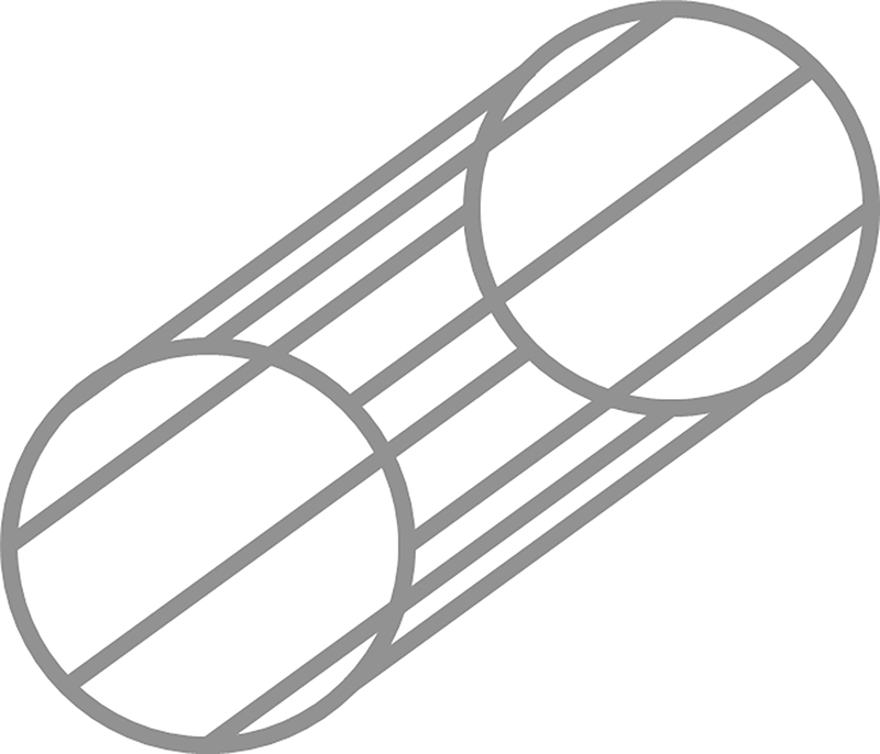
Electromagnetic torque conversion and power generation have also been developed in a single unit for a wind turbine. This configuration is being called pseudo direct drive [32]. The low-speed input is converted to a higher speed through three hollow cylinder rings placed inside each other. The outer and inner rings have permanent magnets arranged in alternating north–south patterns. The middle ring consists of steel segments that alter the magnetic field between the inner and outer ring. It is this ring which is connected to the low-speed shaft. Stator windings are then placed around the outside magnetic ring as seen in Fig. 8.27. This allows for a current to be induced in the windings as the magnetic outer ring rotates inside the stator.

8.5.5. Concluding remarks
Offshore wind turbine manufacturers have started to adopt electrical generator technologies which are somewhat different to those used on onshore, mainly because of the different challenges which are met offshore. Whereas the development of generators onshore has adapted existing low-cost, industrial electrical machine technologies to suit wind turbines, the emphasis offshore is on more tailored solutions which can deliver high efficiency and high availability. There is a wide variety of approaches currently being used in offshore wind and it is still not clear which technical solution will ultimately dominate. This means that the research and development of offshore wind turbine generators continues to be an exciting field of endeavour.
Sources of further information
There are many excellent textbook on the study of electric machines. These can be useful to further understand and explore some of the basics of rotating electrical machines. Some of the better texts include:
• P.C. Sen, Principles of Electric Machines and Power Electronics, John Wiley & Sons, 2007.
• A.E. Fitzgerald, C. Kingsley, S.D. Umans, Electric Machinery, McGraw-Hill, 2003.
• J. Hindmarsh, Electrical Machines and Their Applications, Butterworth-Heinemann, 1995.
• A. Hughes, B. Drury, Electric Motors and Drives, Elsevier, 2013.
The adaptation of electrical machines for use in renewable energy is sometimes only briefly addressed in some of these classic texts. The reader may be interested in these books which explore the wind turbine context, the interaction of the generator with some of the other subsystems as well as some of the practical aspects in more detail:
• M. Mueller, P. Polinder (Eds.), Electrical Drives for Direct Drive Renewable Energy Systems, Woodhead Publishing (2013).
• V. Akhmatov, Induction Generators for Wind Power, Multi-Science Publishing, 2007.
Although the reader may be aware of the journals focusing on wind and other renewables, much of the up-to-date research on wind turbine electrical generators is published in journals that focus on the electrical machine itself. The following are good examples:
• IET Electric Power Applications, Online ISSN 1751–8679, Print ISSN 1751-8660
• IEEE Transactions on Energy Conversion, ISSN: 0885-8969
..................Content has been hidden....................
You can't read the all page of ebook, please click here login for view all page.