
Symbols
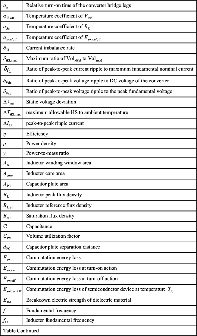
| αa | Relative turn-on time of the converter bridge legs |
| αVsw0 | Temperature coefficient of Vsw0 |
| αRc | Temperature coefficient of RC |
| αEon/off | Temperature coefficient of Esw,on/off |
| δCI | Current imbalance rate |
| δHS,max | Maximum ratio of VolHSal to Volmod |
| Ratio of peak-to-peak current ripple to maximum fundamental nominal current | |
| δVdc | Ratio of peak-to-peak voltage ripple to DC voltage of the converter |
| δVac | Ratio of peak-to-peak voltage ripple to the peak fundamental voltage |
| ΔVsw | Static voltage deviation |
| ΔTHS,max | maximum allowable HS to ambient temperature |
| ΔILh | peak-to-peak ripple current |
| η | Efficiency |
| ρ | Power density |
| γ | Power-to-mass ratio |
| Aw | Inductor winding window area |
| Acore | Inductor core area |
| APC | Capacitor plate area |
| BL | Inductor peak flux density |
| BLref | Inductor reference flux density |
| Bsat | Saturation flux density |
| C | Capacitance |
| CPV | Volume utilization factor |
| dPC | Capacitor plate separation distance |
| Esw | Commutation energy loss |
| Esw,on | Commutation energy loss at turn-on action |
| Esw,off | Commutation energy loss at turn-off action |
| Esw0,on/off | Commutation energy loss of semiconductor device at temperature Tj0 |
| EBd | Breakdown electric strength of dielectric material |
| f | Fundamental frequency |
| fL1 | Inductor fundamental frequency |
| Table Continued | |
| fLref | Inductor reference frequency |
| feff | Effective frequency for a non-sinusoidal current waveform |
| fsw | Switching frequency |
| HS | Heat sink |
| iL1 | Inductor fundamental current |
| iLh | Inductor ripple current |
| isw | Semiconductor device current |
| iswb | Current through the PSD at moment before turn-on action |
| iswa | Current through the PSD at moment after turn-off action |
| Ip,AVG | Average current in the parallel connection of PSDs |
| Ipsw | Peak current of the parallel connection of PSDs |
| Isw,AVG | Average conduction current of semiconductor device |
| Isw,RMS | RMS conduction current of semiconductor device |
| Isw,eq | Equivalent current of parallel connected PSDs for power losses calculation |
| Isw,Total | Total current of parallel connected PSDs |
| Iswa,AVG | Average current through the PSD at moment after turn-on action |
| Iswa,RMS | RMS current through the PSD at moment after turn-on action |
| Iswb,AVG | Average current through the PSD at moment before turn-off action |
| Iswb,RMS | RMS current through the PSD at moment before turn-off action |
| Inductor peak current | |
| IL | Inductor RMS current |
| JL | Inductor RMS current density |
| Jmax | Maximum current density |
| kcdp | Derating factor |
| kvp | Safety factor of PSD for peak voltage |
| kvdc | Safety factor of PSD for DC voltage |
| kwc | Winding conductor fill factor |
| Polynomial regression coefficients for the current dependency of Esw,on/off | |
| KHSx | Proportionality regression coefficients for heat sink volume |
| Kfanx | Proportionality regression coefficients for fan volume |
| KVLx | Proportionality regression coefficients for inductor volume |
| KρLx | Proportionality regression coefficients for inductor mass |
| Kρwx | Proportionality regression coefficients for inductor winding losses |
| Table Continued | |

| Kρcx | Proportionality regression coefficients for inductor core losses |
| KVCx | Proportionality regression coefficients for capacitor volume |
| KρCx | Proportionality regression coefficients for capacitor mass |
| KΩCx | Proportionality regression coefficients for capacitor series resistance |
| KSFT | Safety factor of thermal design |
| L | Inductance |
| MS | Modulation index |
| ma | Phase modulation function |
| MassTotal | Total converter mass |
| Massvalve | Mass of the power switch valve |
| MassL | Inductor total mass |
| MassC | Capacitor total mass |
| Mass(i) | Individual mass of the components |
| N | Number of switching actions |
| Nisxm | Number of internal semiconductor devices per module |
| np | Number of parallel connected devices |
| ns | Number of series connected devices |
| Pin | Power input |
| Ploss,mod | Total power losses of a PSD |
| PL | Inductor power losses |
| PC | Capacitor power losses |
| PεC | Capacitor dielectric losses |
| PΩC | Capacitor resistive losses |
| PWL | Inductor winding losses |
| PcoreL | Inductor core losses |
| Pcond | Conduction losses |
| Psw | Switching losses |
| RC | On-state resistance of semiconductor device |
| RC0 | On-state resistance of semiconductor device at temperature Tj0 |
| RthHS | Thermal resistance of the HS for a given fan velocity |
| RthHS,min | Minimum thermal resistance of the HS for a given fan velocity |
| Rth,igbt | Thermal resistance of the IGBT device |
| Table Continued | |

| Rth,diodet | Thermal resistance of the diode device |
| RthJC | Junction-to-case thermal resistance of the device |
| RthCH | Case-to-heat sink thermal resistance of the device |
| RsC | Capacitor series resistance at maximum hot-spot temperature |
| T | Fundamental period |
| Tamb | Ambient temperature |
| Tsw | Switching period |
| Tj | Junction temperature of semiconductor device |
| Tj0 | Fixed reference junction temperature of semiconductor device |
| Tj,AVG | Average junction temperature of semiconductor device |
| Vbk | Nominal blocking voltage of semiconductor device |
| VCN | Capacitor-rated voltage |
| VCac | Maximum amplitude of the alternating voltage applied to capacitor |
| Vfan | Fan velocity |
| VDC,max | Maximum DC voltage of the series connected PSD array |
| VLL | Line-to-line RMS voltage |
| Vp,max | Maximum voltage amplitude to be blocked for the series connected PSD array |
| vsw | Semiconductor device voltage |
| vswb | Voltage in the PSD at moment before turn-on action |
| vswa | Voltage in the PSD at moment after turn-off action |
| Vsw0 | Threshold voltage of semiconductor device |
| Vsw00 | Threshold voltage of semiconductor device at temperature Tj0 |
| VolTotal | Total converter volume |
| Vol(i) | Individual volume of the components |
| Volmod | Semiconductor module volume |
| Volvalve | Volume of a power switch valve |
| VolHS | Heat sink volume |
| VolHSal | Volume of aluminium/copper structure |
| Volfan | Fan volume |
| VolC | Capacitor total volume |
| VolL | Inductor total volume |
| VolPC | Volume of a plate capacitor |

..................Content has been hidden....................
You can't read the all page of ebook, please click here login for view all page.