
10.2. Function and types of towers
Since the inception of the wind industry, the towers have been considered as one of the key components for wind turbines as they perform two fundamental functions: (1) provide access to a favorable wind resource by supporting the rotor at a sufficiently high hub height; and (2) provide a safe and reliable load path from the turbine to the foundation. In the following subsections, an overview of layout options for both land-based and offshore SSts is given. These alternatives differ in geometric layout and load paths, utilized materials, or both. Regardless of these choices, the towers must guarantee that the system modal characteristics are kept within the acceptable bounds and away from the turbine excitation frequency bands. Special attention must also be paid to the fabrication costs, and the transportation and installation procedures, which may make one alternative more or less favorable for a specific site and turbine configuration. While the one-size-fits-all model is attractive, rarely one particular design can be applicable to many different environments and applications. In fact, it is becoming progressively more crucial to optimize the entire turbine from a system perspective, where all project aspects, from the structural performance to the BOS costs, are considered.
10.2.1. Full lattice, tubular, and wooden towers
Several configurations have been explored throughout the history of the wind power industry, and several different criteria have led to the widespread use of the tubular design. Lattice structures, quite common in the first installations, see Fig. 10.1, have mostly been abandoned on the account of aesthetics and environmental concerns. From an environmental perspective, these towers offer roosting/nesting places for birds and thus may raise the probability of bird strikes.
Tubular towers are normally made up of cylindrical or conical frustum segments of 20–30 m in length, which are transported separately and bolted together at their ends (flanges) on site. As such, tubular towers allow for an enclosed space in which to locate power electronics and switchboards, and protect maintenance personnel from the environment.
A lattice tower, however, allows for a stiff, yet very light structure by placing the main steel away from the neutral axis. The first lattice towers were designed following the electrical transmission line experience, where angle iron components were bolted or welded together to form the lattice. Larger turbines, as the 160-m hub height, Fuhrlander FL 2500 shown in Fig. 10.2, require larger members, and the bolted connection at the joints becomes prohibitive especially for numerous applications such as those in large wind farms. Checking bolt torque levels, clearing the towers of debris or ice, and even safe access for maintenance staff can be too expensive or difficult to achieve. Also to note is the need for a TP to house the yaw bearing. The design of this component is critical as it must allow for the transition from polygonal to circular cross-section and for the safe transfer of the distributed load at the yaw bearing to the concentrated loads in the main lattice legs.

Figure 10.1 Example of free-standing lattice tower used for old wind turbines at Altamont, California (a) and Tehachapi, California (b) wind farms. Photos courtesy of NREL Pix Library, numbers 17329 and 18457.
Slender masts with guy wires have been used for turbines of submegawatt size, as seen for example in Fig. 10.3. Guyed towers are light, easy to transport, and allow for the entire structure to be brought down to the ground for maintenance. Unfortunately, for large turbine sizes, the guys would require a very large footprint, making the installation more cumbersome, and given the number and wire diameter sizes would also affect the quality of the wind, not to mention the impediments associated with environmental issues.
Fiber-reinforced polymer towers (see Fig. 10.5) and wooden towers have also been used for water-pumping windmills in the past, and at present for small wind turbines. Today, there are proponents of engineered wood for utility scale turbines, and one such example has been certified by TÜV and deployed in Germany by Timber-Tower, GmbH (see Fig. 10.4). Wood offers some economical advantages thanks to the ease of laminate manufacturing, competitive strength/weight ratio, and stable costs. Transportation issues are also relaxed and direct local sourcing is a possibility. However, wooden towers have not found a great deal of application in the industry. Composite and hybrid towers are currently being investigated (eg, Refs [5–8]). In principle, composite materials may render better fatigue characteristics, increased structural damping, reduced logistics costs, and possibility of on-site construction. However, it still has to be proven that these advantages offset manufacturing and material costs to make this option viable.

Figure 10.2 The Fuhrlander 2.5 MW Laasow (FL 2500) was touted as the world's tallest wind turbine until a few years ago. The lattice tower is 160 m high and the blade tip reaches 205 m. The new MHI-Vestas V164–8.0-MW turbine is being tested in Österlid, Denmark atop a ∼140-m tower, and the blade tip reaches 220 m. Copyright http://en.wikipedia.org/wiki/Fuhrl%C3%A4nder_Wind_Turbine_Laasow.
10.2.2. Manufacturing and installation challenges on land
The steady decrease in prime real estate with high wind resource at low altitude, grid availability, and no environmental concerns or public interaction, translates into the need for higher hub heights. In many sites where the wind resource at 80 m (the standard hub height for most utility scale wind turbines in the U.S.) is only marginal, the presence of a significant wind shear means that the resource at 120–150 m hub height becomes economically feasible for development. For example, it is calculated that 1800 GW of wind power potential across 237,000 square-miles of the U.S., or an area roughly the size of Texas [9], could be unlocked by wind turbines with hub heights of up to 140 m. Furthermore, the ever-growing size of turbine rotors necessary to guarantee economical capacity factors in less windy areas, demands taller and bigger towers. Finally, repowering old wind farms with new, larger turbines, and the possibility of adopting staggered siting with different hub heights to reduce wake losses in a wind array, call for taller towers too.

Figure 10.3 The GEV MP C series consists of two-bladed, downwind wind turbines mounted on tilt-up, guyed towers. Rotor diameters reach 32 m and the hub height reach 60 m. Vergnet Eolien http://www.vergnet.com/en/gevmpc.php.

Figure 10.4 Example of a 100-m wooden tower for a Vensys 1.5 MW turbine in Germany. TimberTower GmbH, Hannover, Germany. http://www.timbertower.de/tower-construction/.

Figure 10.5 Examples of GFRP towers: (a) small wind turbine application (Photo courtesy of NREL); (b) utility scale turbine tower getting ready for structural testing. http://www.cres.gr/megawind/COMPOSITE_MATERIAL_TOWER.htm visited on 2/20/2015.
Tubular steel towers have reached a limit of applicability on land: larger turbine heads require large base diameters to meet safe frequency-band criteria, but transportation limitations (eg, bridge clearance) impose a difficult limit on the maximum hauling girth (4.3 m in the U.S.). Increasing wall thickness may partially mitigate the problem, but it can only be achieved through expensive fabrication processes (because of plate rolling and welding constraints). Beside guaranteeing permits for blade tips approaching 200 + m above ground level (AGL), the challenge for large towers on land is thus how to address the transportation challenges, and also how to facilitate turbine erection to those heights. In the U.S., for instance, there are only some 10 crawler cranes in the class (1250 and 1600 t) needed for erections of 3- and 5-MW turbine nacelles and towers [9]. Future designs will necessarily be “designs for production” accounting for new and on-site manufacturing techniques, different materials, and/or innovative transportation and installation strategies.
10.2.3. The promise of concrete
Two alternatives that have been successful on land and that can at least partially bypass the above logistical constraints are the reinforced concrete tower and the hybrid concrete–steel tower. In the latter, the concrete base (a pedestal) supports the upper, more conventional, steel portion. There are several advantages to utilizing concrete. Concrete is an inherently durable material that can retain the required engineering properties under various environmental conditions; it offers corrosion protection to the reinforcing material (steel or composite), and presents high fatigue resistance and damping characteristics; it can be tailored both in inner constituents (for example to achieve different degrees of strength or to achieve crack-resistance and self-healing properties) and in the shape of the casting and arrangement of the reinforcement [10]. Concrete can be sourced locally and is also easily recyclable as aggregate material. Quality control on precast panels can guarantee tight tolerances and finishes, whereas established formwork solutions and mobile mixing plants can enable on-site construction without transportation impediments. The versatility of concrete can be used by the designer to tailor structural properties along the height of the tower, to take advantage of modularity in precast panels, and, through the employment of prestress, to achieve high hub heights with minimum steel quantities. The possibility of tuning the system eigenfrequencies by changing the amount of prestress is very attractive. Furthermore, by adapting the level of prestress via post-tensioned tendons, installations could be repowered for larger machines as long as the foundation is designed to cope with larger stresses. It is argued that some form of prestressed reinforced concrete (pre- or post-tensioned, and steel or composite fiber-reinforced) is the only technology that can unlock the highest hub heights while bypassing the land transportation restrictions. The 7.5-MW E-126 Enercon (see Fig. 10.6) features a prefab concrete tower with a 14.5 m base diameter and a 135 m hub height. Obviously, even though transportation logistics are overcome by interlocking concrete panels, the tower and turbine erection remains a formidable challenge in the quest for low project costs.

10.2.4. From onshore to offshore
The vast experience gained onshore with wind turbine generators (WTGs) can only be partially applied to OWTs, as important differences exist between onshore and offshore. The variety of SSts and foundations, the addition of hydrodynamic loads, extreme corrosive environments, the vital need to minimize maintenance more than on land due to the extremely expensive operation and maintenance (O&M) are just a few of these differences. Oil and gas (O&G) experience can certainly be tapped, but differences in the systems between wind and O&G, such as larger wind loading, structural dynamics, and structural non-linearities still make the engineering of an OWT very unique. For this reason, the so-called fully coupled approach, where the entire system (from the WTG to the foundation, including effects of aerodynamics, hydrodynamics, servo-mechanics, and structural dynamics) is analyzed with ad hoc tools is the preferred and most rigorous design method.
From a loading standpoint, important differences can be listed. Offshore sites tend to have steeper shear and less turbulent wind profiles due to reduced roughness; this, in addition to affordably lower hub heights, decreases the aerodynamic periodic loads. However, offshore climates are generally characterized by Weibull wind distributions with larger scale and shape factors, which lead to higher mean wind speeds and higher overall probabilities of large wind speeds and gusts. Additionally, it can be expected that array wake effects on turbine inflow are more important offshore, as the wake structures decay more slowly in a less turbulent environment. Therefore, one may expect a greater power output but also higher mean load levels when going offshore.
Moreover, the absence of significant damping when the rotor is parked or idling can be an important design situation for offshore towers. In some situations, for instance with large hub heights and deep water sites, the hydrodynamic loads may dominate the fatigue damage equivalent loads (DELs). If a turbine is shutdown in high winds, the associated severe sea state may induce vibrations in the SSt, that are significantly underdamped. A similar situation may occur during operational conditions if wind and waves are misaligned, in which case the side-to-side oscillations are also lightly damped. This aspect requires more investigation than on land, where idling is normally a benign situation; hence, ad hoc dynamic control strategies and damping devices may need to be employed offshore.
Further aspects specific to OWT SSt include scour, marine growth, and potential vessel impact. Scouring may reduce the natural frequencies of the OWT system with possible resonance-band impingement. Measurements have revealed scouring depths of up to 1.3 times the diameter of the embedded pile. Marine growth will increase mass and hydrodynamic loads in the submerged part of the SSt. Marine growth thickness and depth extents are normally given by site-specific design basis documents or relevant standards (eg, Ref. [11]). Vessel impact is intended to be resisted by the plastic deformation of boat fenders, and accidental impacts elsewhere should not exceed yield strength.
For offshore applications, the transportation constraints are largely relaxed if manufacturing has water (quay-side) access. For this reason and because of the experience gained with systems onshore, mostly tubular steel towers have been used for offshore wind turbines. The towers are connected to the SbSs, which transfer wind and inertial loads from the tower base, and wave and current hydrodynamic loads to the foundation at the seabed. The connection between tower and SbS is ensured by the TP, a component that can take various shapes, but that is essential in guaranteeing the safe and reliable operation of the wind turbine.
The simplest way to put a wind turbine at sea is to consider the typical tubular tower and to extend it all the way below the seabed via the so-called monopile configuration. Since the pile must be driven into the soil via hammers or vibrohammers, it is convenient to separate the pile from the tower above and to connect the two through a TP, normally grouted to the pile. More recent innovations incorporate the TP within the monopile component, which expedites the installation, but requires larger thickness at the top of the pile to guarantee that the action of pile-driving does not push the tower-SbS connecting elements out of tolerance. Deeper waters and larger RNA masses associated with larger turbines have stringent modal requirements that necessitate very large monopiles, which make them uneconomical.
Other fixed-bottom configurations include lattice SbSs (tripod or jackets from the O&G experience) and gravity-based foundations (GBFs) (see Fig. 10.7). The TP in the case of jackets must transfer loads to the primary members (legs) of the SbS and promote the transition from multiple-member to single-tube shapes. Concrete towers have not seen application offshore as of yet, but reinforced concrete has been already used in GBFs (eg, Middelgrunden and Nysted wind farms) and TP grouted connections may be considered special cases of reinforced concrete structures. It is conceivable that prestressed, post-tensioned concrete towers will find applicability, especially married to GBF SbSs and high hub heights, given the advantages mentioned in Section 10.2.3. In particular, prefabricated panels can be produced on a dry-dock onshore and easily transported to the site where post-tensioning can be applied during installation. The aggressive corrosive environment must be counteracted with adequate protection of the steel reinforcements and tendons. This translates into constructive measures (minimum protective distance of concrete outer surface from rebars) and concrete formulation (strength and density of the concrete). For GBFs, transportation via towing operations and controlled sinking further require floating stability checks.

Figure 10.7 Examples of fixed-bottom systems: (a) from left to right, monopile, tripile, tripod, jacket, and gravity foundation. Examples of real offshore installations of turbines on fixed-bottom SbSs: (b) monopile; (c) jacket; (d) tripile; (e) shows GBFs under construction at the quayside.
Floating SbSs, or platforms, include semisubmersible (stability guaranteed by buoyancy and restoring mooring), spars (stability guaranteed by gravity), and tension leg platform (TLP) (stability guaranteed by excess buoyancy) (see Fig. 10.8). These systems promise economic advantages, especially in deeper waters, where material and installation costs make fixed-bottom structures economically unfeasible. Of course, floating configurations have their own unique challenges, and again are quite different in terms of dynamic behavior from the O&G counterparts. The towers that are mounted on floating platforms are still designed according to the same design procedures as those of fixed SbSs, but wave excitation and hydrodynamic loading become even more important. With floating OWTs, controls are key for dampening dangerous oscillations throughout the system and the tower in particular. Currently installed examples include turbines on a spar and a semisubmersible (Statoil's Hywind [12] and Principle Power's WindFloat [13]).
A hybrid configuration which promises certain advantages is the hinged, floating tower [11]. Guy wires help the stabilization of the tower from above the mean sea level to the seafloor. An example of a floating tower is shown in Fig. 10.9.

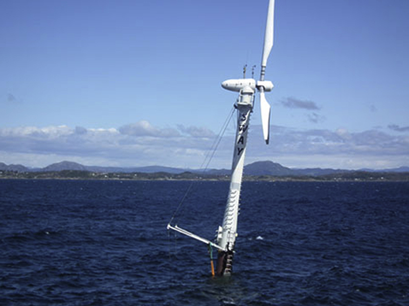
Figure 10.9 Example of hinged, floating tower. SWAY's system consists of a downwind turbine supported by a floating tower/spar anchored to the seabed via a tension-torsion leg, which is equipped with a passive, subsea yaw-swivel. The entire structure can yaw around this point. The guy wires are connected to that point and reduce the stress on the tower and spar which can then be made lighter. http://www.sway.no.
Finally, another alternative design is an all-lattice structure, from the seabed to the hub (see Ref. [14] and Fig. 10.2). In this case, there is no distinction between the tower and the SbS, but a TP still needs to be devised to be located at the base of the nacelle to accommodate the yaw bearing and RNA slewing ring. Given the importance of stiffness requirements, the individual members must be of generous proportion to guarantee adequate shear transfer, and the connections at the joints rely on welds that must be carefully verified and inspected. Therefore, fabrication of lattices, including jacket and tripod SbSs, is less amenable to automation and the potential savings in mass can be partially offset by labor costs. Cast joint-cans, where only circular welds have to be made, can mitigate the issue and are also intrinsically more resistant to fatigue.
One important aspect to underline is that the SSt, encompassing both tower and SbS, is site-dependent. Whereas the turbine itself is designed against the specifications in the standards (eg, class IB from [1]) and therefore can be deployed at a number of different sites that feature wind conditions within the turbine class envelope, the SSt will be optimized based on bathymetry, wave and current regimes, modal requirements, and wind statistics.
..................Content has been hidden....................
You can't read the all page of ebook, please click here login for view all page.