
10.3. Standards of reference
Wind power generators and their SSts are dynamically connected and need to be analyzed as a combined system. For this reason, one should seek harmonization between the design of the power generation equipment and that of the SSt. As a result, for the designers of an OWT and its components, navigating the number of codes and standards may be a daunting undertaking. A few guidelines can be used to help in the selection of the design standards.
So far, the majority of offshore wind installations has taken place in Europe, where International Standardization Organization (ISO) and European-specific standards (eg, Ref. [15]), expressed in load resistance factor design (LRFD) format, are widely adopted. In other regions, the choice of design practices and material references should align with locally based guidelines, construction permitting processes, authorities' protocols, material specification, and construction yard practice. Steel properties for shell, flanges, and bolts are commonly given by Refs [16,17].
In the U.S., the American Wind Energy Association (AWEA) issued Ref. [18], which provides overall guidance for offshore wind installations in U.S. waters. For example, Ref. [18] specifies that a 1000-year maximum wave crest level, as also indicated in Ref. [19], should be considered when determining the deck height in the U.S. waters prone to tropical cyclones, which in turn yields the elevation of the tower-base flange. AWEA [18] recognizes that a number of design aspects of OWTs are not adequately covered in existing codified guidance. Where local codes and standards may not suffice, the designers need to refer to internationally recognized codes and regulations that, subject to the owner's engineer's approval, may lead to a safe and reliable design. For instance, standards such as Refs [19,22] are examples of normative references cited by both Refs [18,1].
Offshore towers are fundamentally ruled by Refs [23,1,19], for the pure structural compliance, and by a number of different codes for corrosion protection and manufacturing (eg, Refs [24–26]). In Europe, Refs [3,15] have also been used in place or in conjunction with Ref. [1]; for the SbS and for interface component fatigue limit state (FLS) design (eg, TP and grouted connections), Ref. [11] may also be used. In order to determine the metocean conditions, such as wind and wave regimes per Ref. [1], and to translate them into design parameters, Ref. [27], now aligned with Ref. [28], can be employed. Structural design checks normally are to the ISO 19900 series [3,2]; the latter two are used for global and local/shell buckling verifications. Refs [15,29] also provide guidance for resonance avoidance and SSt frequency placement (see Section 10.4.1.2).
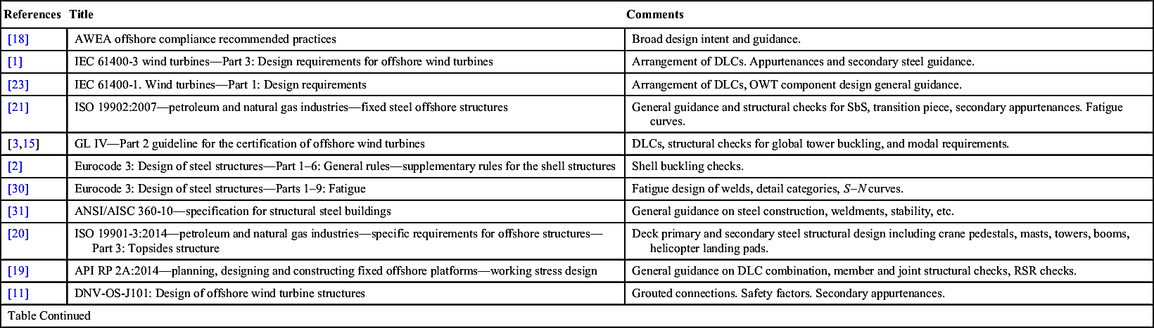
Table 10.1 provides a possible selection and prioritization of codes and standards that can be used for design and certification preparation of the SSt; note, however, that many other codes could and should be used in the design of structural details, and local ordinances may require a different hierarchy than the one proposed here.
Finally, all materials, fabrication, tolerances, workmanship, etc. shall conform to the codes adopted for design. The SSt designer shall comply with all necessary technical and procedural requirements advised by the owner's engineer, the WTG manufacturer and the certification and verification agency (CVA). In particular, welding specifications and detailing for the SSt should adhere to Refs [30,39]; locally accepted codes may also be used as long as they meet the approval of the CVA, because they represent an integral part of the WTG certification.
Table 10.1
Possible prioritization in the codes and standards for the design of an offshore tower
| References | Title | Comments |
| [18] | AWEA offshore compliance recommended practices | Broad design intent and guidance. |
| [1] | IEC 61400-3 wind turbines—Part 3: Design requirements for offshore wind turbines | Arrangement of DLCs. Appurtenances and secondary steel guidance. |
| [23] | IEC 61400-1. Wind turbines—Part 1: Design requirements | Arrangement of DLCs, OWT component design general guidance. |
| [21] | ISO 19902:2007—petroleum and natural gas industries—fixed steel offshore structures | General guidance and structural checks for SbS, transition piece, secondary appurtenances. Fatigue curves. |
| [3,15] | GL IV—Part 2 guideline for the certification of offshore wind turbines | DLCs, structural checks for global tower buckling, and modal requirements. |
| [2] | Eurocode 3: Design of steel structures—Part 1–6: General rules—supplementary rules for the shell structures | Shell buckling checks. |
| [30] | Eurocode 3: Design of steel structures—Parts 1–9: Fatigue | Fatigue design of welds, detail categories, S–N curves. |
| [31] | ANSI/AISC 360-10—specification for structural steel buildings | General guidance on steel construction, weldments, stability, etc. |
| [20] | ISO 19901-3:2014—petroleum and natural gas industries—specific requirements for offshore structures—Part 3: Topsides structure | Deck primary and secondary steel structural design including crane pedestals, masts, towers, booms, helicopter landing pads. |
| [19] | API RP 2A:2014—planning, designing and constructing fixed offshore platforms—working stress design | General guidance on DLC combination, member and joint structural checks, RSR checks. |
| [11] | DNV-OS-J101: Design of offshore wind turbine structures | Grouted connections. Safety factors. Secondary appurtenances. |
| Table Continued | ||
| References | Title | Comments |
| Reinforced concrete structures codes and standards | ||
| [32] | ACI 318-14—building code requirements for structural concrete and commentary | Reinforced concrete SSt. |
| [33] | ACI 357R-84—guide for the design and construction of fixed offshore concrete structures | Gravity based foundations. |
| [22] | ISO 19903:2006—petroleum and natural gas industries—fixed concrete offshore structures | General guidance for offshore RC structures. |
| [34] | Eurocode 4: Design of composite steel and concrete structures | |
| [35] | Eurocode 2: Design of concrete structures | To be used in conjunction with Ref. [34] |
| [36] | Model code for concrete structures 2010 | High load cycle number fatigue design of pre-stressed concrete. |
| [37] | NS 3473—concrete structures—design rules | High load cycle number fatigue design of pre-stressed concrete. |
| Floating wind turbine design standards | ||
| [11] | DNV-OS-J103: Design of floating wind turbine structures | Materials and PSFs. Station keeping. |
| [38] | Guide for building and classing—floating offshore wind turbine installations | Floating wind turbine design. |
| Additional reference standards | ||
| [39] | AWS structural welding code—steel | Welding specifications and detailing. |
| [40] | VDI 2230 Part 1: Systematic calculation of highly stressed bolted joints | Bolted connection specifications and detailing. |
| [41] | DNV-RP-C203: Fatigue strength analysis of offshore steel structures | Guidance on fatigue analysis of offshore structures. |
| [42] | ABS guide for building and classing—bottom-founded offshore wind turbine installations | Special DLCs for hurricane-prone regions. |
| Table Continued | ||

| References | Title | Comments |
| [43] | ABS guide for buckling and ultimate strength assessment for offshore structures | Member design, buckling assessment, material PSFs. |
| [44] | ABS guide for fatigue assessment of offshore structures | Member design, fatigue design, S–N curves. |
| [27] | API RP 2MET: Derivation of metocean design and operating conditions | General guidance on metocean conditions derivation. |
| [45] | API RP 2SIM: Structural integrity management of fixed offshore structures | |
| [46] | API RP 2GEO: Geotechnical and foundation design considerations | General guidance on foundations design. |
| [47] | NORSOK classification note no. 30.4: Foundations | For foundation stiffness, lateral capacity etc. |
| [48] | IEC 60364—Electrical installations of buildings Part 5–54: Selection and erection of electrical equipment earthing arrangements, protective conductors and protective bonding conductors | Grounding protection. |
| [49,50] | ISO 12944 paints and varnishes—corrosion protection of steel structures by protective paint systems | Corrosion protection and coatings. |
| [24] | NORSOK M-501: Surface preparation and protective coating | Coatings. |
| [16] | EN 10025: 2004—European structural steel standard | Structural steel specifications. |
| [17] | EN 14399: High-strength structural bolting assemblies for preloading | Bolt assemblies properties. |

10.3.1. Advanced standards development
In the U.S., Ref. [18] defines OWTs as L2 structures following Ref. [51] (see Table 10.2), associated to medium consequences of failures in the event of structural collapse. The consequences of failure are mostly linked to lost revenues and potentially adversary national policy consequences for an industry that is still very young. The exposure category has direct impact on the reliability level assumed (or 1 − probability of failure). There is still ongoing debate on what the appropriate level of reliability in U.S. waters should be Refs [42,52,53]. Especially in hurricane-prone waters, in fact, it can be argued that the level of reliability achievable following Ref. [1], which was calibrated to European conditions, might be less than that in the North Sea [42]. A counterargument states that the reliability index of northern Europe might be overly conservative, as it was originally derived from the O&G experience in the Gulf of Mexico.
Table 10.2
Exposure levels based on life safety and consequence categories
| Life-safety category | Consequence category | |||
| C1 high consequence | C2 medium consequence | C3 low consequence | ||
| S1 | Manned non-evacuated | L1 | L1 | L1 |
| S2 | Manned evacuated | L1 | L2 | L2 |
| S3 | Unmanned | L1 | L2 | L3 |

From ISO 19900: 2013-Petroleum and Natural Gas Industries – General Requirements for Offshore Structures. Revision to 2002 edition, 2013.
These aspects will be revisited by the standards' technical committees in the upcoming years, and the new edition of Ref. [1], for instance, will have informational content on design in tropical cyclone regions and on adequate approaches to guarantee an appropriate level of safety (eg, robustness and reserve strength ratio verifications in line with Ref. [19]).
One method to calibrate the reliability of the SSt design makes use of the so-called hazard curves. The curves help identify the risk of failure via an assessment of the overload hazard as a function of the metocean event return periods (RPs) [53] (see also Fig. 10.11 for a few examples of hazard curves). In Fig. 10.11(a), the ratio of the overturning moment at the base of the SSt (or tower) calculated as the response to a ultimate limit state (ULS) event at a given RP, to the same load for a 50-year RP, is graphed. The latter is the basic RP indicated, for example, by Ref. [1] for maximum gusts and wave loads. In regions where tropical cyclones (hurricanes and typhoons) are present, the hazard of overloading the structure could be higher than in extratropical storm regions (see also Fig. 10.10). This is indicated by the steeper slope of the “Gulf of Mexico” curve in Fig. 10.11(a) as opposed to the “New England” curve.
A set of hazard curves can also be used to evaluate the necessary load factor (LF) to achieve a certain reliability level. While the topic is more complex than this chapter may cover, the concept may be shown by the curves in Fig. 10.11(b). In that figure, the reliability level associated with a 500-year RSR (from Ref. [19]) is used to determine the necessary LF for an SSt (four-legged jacket and tower) in a tropical-cylone-prone region. As can be seen, the necessary PSF is larger than the 1.35 recommended by Ref. [1].


Figure 10.11 Examples of hazard curves for a typical tower and four-legged jacket SSt: (a) for two regions in the U.S., more (Gulf of Mexico) and less (New England) prone to tropical cyclone overload hazard, respectively; (b) an example showing the required LF for an installation in a hurricane-prone region in order to meet the 500-year RSR recommended by Ref. [19].

Over the years, the O&G industry has conducted several rigorous reliability studies that have also been validated by hundreds of installations [19,54–60]. The offshore wind industry could potentially rely on that experience, but OWTs are significantly different from O&G platforms, both from a structural and an economic point of view, and will need to be studied appropriately to arrive at an optimum reliability and cost balance. Hazard curves and reliability studies are tools that can in the end lead to a more balanced design where the overall life cost of the project (comprising both installed and lifecycle cost) is minimized as graphically shown in Fig. 10.12.
As a general rule, the early involvement of the project CVA is encouraged as that may further aid in the selection and prioritization of the standards to be used and allow the designer to fine-tune the PSFs to achieve the most economical design with an optimum level of reliability.
..................Content has been hidden....................
You can't read the all page of ebook, please click here login for view all page.