11

Design of floating offshore wind turbines

M. Collu     Cranfield University, Bedford, United Kingdom
M. Borg     Technical University of Denmark (DTU), Lyngby, Denmark

Abstract

The floating wind industry is still in its infancy, with just a few scaled-down prototypes deployed around the world, but at the same time there is a lot of interest in this new field, since it is deemed to play a major role in the future of offshore wind. In the present chapter a classification methodology for floating offshore wind turbine (FOWT) systems is presented, followed by some considerations about their conceptual/preliminary design. In doing so, some of the basic concepts and principles are illustrated, starting from the theories developed for oil and gas offshore floating support structures, but adapting/modifying them specifically for FOWT. Then, the key issues in the design of FOWT are presented, such as the lack of design integration, the need for new and specific guidelines and standards, the limits of the numerical models available and the impact of the floating platform on turbine loading. A case study is then presented, and a look into the future trends that have emerged in the latest years is given.

Keywords

Floating wind turbines; FOWT; HAWT; Hydrostatics; Offshore wind; Response to wind and wave; Rigid body dynamics; VAWT

11.1. Introduction

As countries aim to generate more electricity from wind energy, the exploitation of offshore wind energy resources has become increasingly important. The significantly larger wind resources available offshore in water depths greater than 50 m have attracted interest in developing floating support structures for wind turbines as fixed foundations do not remain economically viable (Collu et al., 2010). As many countries, such as Japan, the United States and European countries along the Atlantic Ocean, have very limited areas with shallow water depths (below 50 m), the economic barrier of fixed support structures, such as monopoles and jacket structures, can be overcome with floating support structures.
In the pursuit of deploying floating wind turbine technology in the offshore environment, a small number of large-scale prototypes have been tested offshore, bringing the technology closer to market and raising the Technology Readiness Level of such technology to 7–8. However, these designs have been conservative in nature to reduce the risks involved, and hence more costly. The use of traditional offshore oil and gas industry design standards and technology also increases costs as safety margins inflated associated capital costs.

11.1.1. Classification of floating wind turbines

11.1.1.1. Classification based on static stability

Floating wind turbines are generally classified based on the configuration of the support structure adopted. The support structure is classified based on the main approach adopted to fulfil the static stability requirements in the rotational degrees of freedom (pitch and roll), ie, how the structure counteracts the inclining moment due mainly to the aerodynamic forces acting on the wind turbine.
As will be derived in Section 11.2.2, the total pitch/roll restoring moment (counteracting the inclining moment) can be calculated as the sum of three contributions:

MR,roll=(ρgIxxα+FB·zCBmg·zCGβ+C44,moorγ)sin(ϕ)MR,pitch=(ρgIyyα+FB·zCBmg·zCGβ+C55,moorγ)sin(θ)

image [11.1]

where α is the ‘waterplane area’ contribution, proportional to the seawater density (ρ), the gravitational acceleration constant (g), and the second moment of the waterplane area (in roll, Ixx, and in pitch, Iyy). If this is the main contribution to the roll/pitch restoring moment, the support structure is said to be ‘waterplane stabilised’; β is the contribution due to the relative position of the centre of buoyancy (B) and the centre of gravity (G), and it is usually called somewhat inaccurately the ‘ballast’ contribution, even if it is linked not only to the vertical position of the G (inertial characteristic), but also to the vertical position of the B (geometric characteristic). The name derives from the fact that usually a large amount of ballast material is used in a position close to the keel of the structure to lower the global G position. FB is the buoyancy force, while m is the total mass of the support structure. Due to the fact that the mooring system imposes a downward force on the floating support structure, in general FB is higher than the total weight of the floating offshore wind turbine system (FOWT) (mg). If this is the main contribution to the roll/pitch restoring moment, the support structure is said to be ‘ballast stabilised’; γ is the contribution due to the mooring system. While this contribution can be considered negligible for catenary mooring systems, it can be the main pitch/roll restoring mechanism for TLP (Tension-Leg Platform) systems. In this case, the FOWT is said to be ‘mooring stabilised’.

11.1.1.2. Classification societies

Bureau Veritas (BV, 2010) adopts the classification criterion illustrated in the previous section, having three categories: ballast floating platforms (term β), tension leg platforms (term γ), and buoyancy floating platforms (term α).
The American Bureau of Shipping (ABS, 2013) adopts a criterion based on the structural elements of the different floating support structures, without expressly mentioning the stabilising mechanism. It distinguishes among ‘TLP-type’, ‘SPARType’, and ‘Column-Stabilised’ floating support structures. Nonetheless, these three categories can be related, respectively, to the terms γ, β, and α in Eq. [11.1].
In the Det Norske Veritas (DNV, 2013) offshore standard ‘Design of Floating Wind Turbine Structures’, the criterion adopted is different from the previous ones, and it considers whether a structure is restrained (displacements in the order of centimetres) or compliant (displacements in the order of metres and above) in global modes of motions.

11.1.2. Floating wind turbines: examples

11.1.2.1. SPAR: Hywind demo by Statoil

Hywind demo by Statoil is a 2.3-MW (Siemens SWT-2.3–82) FOWT system using a SPAR as a floating support structure. Installed in 2010, 12 km off the island of Karmøy, north of Stavanger, in Norway, it is the world's first full-scale floating wind turbine (Statoil, 2010).
As for every SPAR system, it is characterised by a large draught (100 m), making it a suitable solution only for deep waters. As mentioned in Section 11.1.2.1, a SPAR system relies mainly on term β of Eq. [11.1] to ensure its static stability in roll and pitch, ie, on a low vertical position of the G relatively to the B. For Hywind, this is achieved through a combination of heavy materials (rocks) and seawater ballast tanks at the bottom of the hull.

11.1.2.2. Semi-submersible/tri-floater: WindFloat prototype (WF1) by Principle Power and Fukushima FORWARD phase I (Mirai)

WindFloat prototype (WF1) The WindFloat prototype was deployed in October 2011, 5 km off the coast of Aguçadoura, Portugal, by Principle Power, equipped with a Vestas 2.0-MW wind turbine (Principle Power, 2012). It is a three-legged, semi-submersible type, floating platform. This configuration is also called a ‘Trifloater’.
In this case, the static stability is achieved mainly through the large second moment of the waterplane area (term α in Eq. [11.1]), thanks to three relatively large water-piercing cylindrical columns (10.7 m diameter), and a column centre-to-centre distance equal to 56.4 m.
This allows the structure to have a relatively shallow draft, and therefore the possibility to be deployed in relatively shallow waters. Principle Power claims that a 5-MW WindFloat system can have a draught lower than 20 m, and be deployed in a water depth higher than 40 m.
This system is fitted with the patented water entrapment (heave) plates at the base of each column. This system has two main effects: it augments the added mass in heave, reducing its natural frequency (augmenting its natural period, moving it further from the wave peak energy frequency) and it augments the damping in heave, reducing the response of the structure to waves, especially near the system heave natural frequency. Further information is available at http://www.demowfloat.eu/.
Fukushima FORWARD Phase I After the Great East Japan Earthquake of 2011, Japan has started a number of initiatives looking at developing its renewable energy technology capabilities and portfolio. Among this, the Fukushima FORWARD (Floating OffshoRe Wind fARm Demonstration project) consortium was formed, funded by the Japanese Ministry of Economy, Trade and Industry. There are two phases to the project FORWARD: Phase I (2011–13), during which a floating substation (Fukushima Kizuna) and a compact semi-submersible FOWT of 2 MW (Fukushima Mirai) were designed, manufactured, and commissioned, which started to produce electricity in November 2013, and Phase II (2014–2015), currently looking at the design, manufacturing and commissioning of two 7 MW FOWT alternative designs: an advanced SPAR and a V-shaped semi-submersible.
The Fukushima Mirai, whose floater design, manufacturing, and commissioning have been coordinated by Mitsui Engineering & Shipbuilding Co. Ltd., consists of one central column, on top of which is installed the 2-MW wind turbine, and three water-piercing side columns, with diameter around 7.5 m, height of 32 m and a draft around 16 m, and a centre-to-centre distance of about 50 m, which, similarly to the WindFloat prototype, provide the static stability thanks to their second moment of area. The three columns are connected to the central one through six horizontal braces and three diagonal braces. The main difference is that for the Phase I prototype FORWARD the wind turbine is installed on the central column, while the WF1 prototype does not have a central column and the wind turbine is installed on top of one of the side columns. Another interesting characteristic of the FORWARD Phase I prototype is that the wind turbine rotor control system not only optimises the power generation depending on the wind speed, but also minimises the floater motion through the wind turbine. This is an advanced feature pioneered by Statoil with the Hywind project (Driscoll et al., 2015). Further information is available at http://www.fukushima-forward.jp/english/research/index.html.

11.1.2.3. TLP: BlueH phase 1 prototype by BlueH

As proof of concept, Blue H Group Technologies Ltd deployed off the coast of southern Italy a 75% scale prototype of their TLP system, equipped with a small wind turbine (0.08 MW). After 6 months at sea, the unit was decommissioned early in 2009 (Blue, 2004b).
In general, a TLP system could potentially be one of the most suitable platforms for offshore wind turbines, as the displacements can be the smallest, if compared to the other floating support structures. The major drawback is the high cost of the mooring system. The TLP concept has been investigated and proposed by a number of companies and research institutes. Unfortunately, little information is available in the literature about the BlueH, but it has been one of the first of the few deployed TLP prototypes. BlueH claims that this technology can be deployed in water in excess of 60 m, thanks also to its patented deployable TLP system (Blue, 2004a).
In principle, a TLP system can have very little waterplane area and a relatively high vertical position of G, since the necessary stability in pitch/roll is achieved through the stiffness of the tension legs of the platform (γ in Eq. [11.1]). Nonetheless, a small waterplane area and relatively high G can pose substantial challenges in terms of stability during the transport phases, while the mooring system is not connected to the platform yet (ie, γ in Eq. [11.1]). For this reason, the floating support structure is usually a hybrid configuration, exploiting the other two stability terms during the transport phases, and the mooring contribution in the operational site.
This is also the case for the BlueH prototype, where the stability during the transport phase is achieved through a combination of a water-piercing multi-column system (second moment of waterplane area) and a heavy ballast system lowering G (part of the deployable TLP mooring system).

11.2. Design of floating offshore wind turbines: main preliminary steps

If the present floating wind turbine concepts and prototypes are analysed, the focus of the design has been on the floating support structure, rather than on the design of the whole system, since the tendency is to adopt an already commercially available horizontal axis wind turbine (HAWT) developed for the fixed offshore wind market. This approach has its advantages, but also its limitations (Sections 11.2.4 and 11.3.1).
In the following sections the main requirements and constraints driving the design of a FOWT will be illustrated. Then they will focus on how to analyse the hydrostatics and ensure the static stability of the structure. Considerations about the best approach to analyse the dynamic response of the structure to the metocean conditions will be given, and to conclude an overview of further aspects to be analysed will be provided.
The present approach is useful to investigate and narrow down the design space of the potential suitable configurations. For a more detailed design, the reader is referred to the documentation issued by the classification societies.

11.2.1. Main requirements and constraints

11.2.1.1. Floatability

The first requirement is to have the sum of the vertical forces equal to zero, ie, the buoyancy force is able to counteract the total weight of the system plus all the other downward forces, such as the mooring forces.
This requirement can be translated into a minimum required draught, sufficient to have the necessary displaced volume V. Nonetheless this requirement is usually less stringent than the other requirements on draught (eg, minimum draught to avoid slamming loads). As a consequence, ballast tanks are required (generally filled with seawater) to satisfy the other more stringent minimum draught requirements.

11.2.1.2. Maximum inclination angle

While FOWT systems can experience relatively large inclination angles (in roll and/or pitch), onshore and fixed-to-seabed offshore wind turbines do not experience such angles. As a consequence, there is very little experience in estimating the performance of wind turbines at large inclination angles, and relatively few data have been presented in literature.
Taking also into account the fact that many of the sub-systems of an offshore wind turbine (bearings, gearbox, generator, etc.) have been designed to operate close to the upright condition, it is necessary to impose a maximum roll/pitch inclination angle.
The exact value of this maximum inclination angle is still open to discussion, but according to the literature a good starting value is 10 degree. It is important to remember that this is the total angle of inclination, the sum of the static and the dynamic angles of oscillations, due, respectively, to the average value (mainly due to the wind) and the oscillation amplitude (mainly due to waves) of the inclining moments. In terms of the design, this requirement can be translated into a floating support structure minimum rotational stiffness (Section 11.2.2).

11.2.1.3. Freeboard height and minimum draught

In heavy storms, the relative vertical motion between the FOWT and the waves can potentially lead to so-called ‘green water loads’, due to a large body of water flowing on the top of the support structure.
In order to avoid these loads it is necessary to have a minimum vertical distance between the mean undisturbed seawater level and the level at which no green water loads are considered, such as the top of the support structure: this distance is the minimum freeboard height. Its value depends on the local metocean conditions, but for a conceptual/preliminary design a good starting value is 10 m.
Slamming can be defined as ‘a phenomenon described broadly as severe impacting between a water surface and the side or bottom of a hull where the impact causes a shock-like blow’ (ITTC, 2014). It occurs when the relative motion between the structure and the water surface is such that the bottom of the floating structure is above the water elevation.
In order to avoid this a minimum draught requirement is imposed that depends on the local metocean conditions. As previously mentioned, in general this minimum draught requirement is more stringent than the one required for floatability, and therefore ballast tanks are required. A good starting value is 15 m.

11.2.1.4. Optimum dynamic response to wind and wave forces

Wave forces impose oscillatory motions to the FOWT system, and these motions should be minimised since they may impact negatively on the system performance. In order to evaluate the response to wind and wave forces two main approaches are adopted: frequency domain and time domain (see Section 11.2.3).
Frequency approach
Through a frequency analysis approach, it is possible to estimate the system regime responses. Once the wind farm site has been chosen, it is possible to model the relative wave spectrum, illustrating how the energy of the waves is spread with respect to the frequencies.
Once a conceptual/preliminary design of the FOWT system is defined, it is possible to derive the main inertial (mass, G and moments of inertia) characteristics of the whole system and the geometric characteristics of the submerged part of the system. From these, it is possible to derive the two main transfer functions linking the amplitude of the wave to the amplitude of the motion of the system. The final transfer function between the amplitude of the oscillation of the structure (at a frequency ω) in the ith degree of freedom (d.o.f.) and a wave of frequency ω of unit amplitude is called RAOi (Response Amplitude Operator).
Using the wave spectrum for the given location and the RAOi of the considered FOWT system, it is possible to estimate the wave response spectrum of that FOWT system in the given location. This wave response spectrum should be minimised in order to minimise the displacements and accelerations of the FOWT system. The important point is that the natural frequencies (periods) of the FOWT system should be outside the most energetic frequency (period) range of the wave spectrum. This depends on the location, but in general wave spectra are most energetic between the 5- and 25 s period (1.25–0.25 rad/s), and therefore the structure should aim at having natural periods above 25 s or below 5 s in all the d.o.f.
An important aspect should be highlighted, since it is a source of misunderstandings. The RAO concept is strictly valid only to estimate the regime response to waves, and by definition is a linear approach. Since the FOWT system experiences substantial aerodynamic forces as well, mathematically speaking if these forces are considered the RAO concept is no longer valid. Nonetheless, the RAO concept is still used, specifying that it is valid just for a given wind velocity (and for a given wind turbine rotational velocity), and sometimes these are called ‘pseudo-RAOs’. It is therefore important to remember that: (1) these ‘pseudo-RAOs’ are valid only for a given wind speed and (2) since the aerodynamic loads are not linear with the wind velocities, an RAO for each wind speed condition is required.
This also highlights the limitations of a frequency approach when analysing the dynamics of FOWT systems.
Time domain
With a time-domain approach, it is possible to adopt a time-domain coupled model of dynamics and therefore be able to take into account nonlinear forces and also estimate the transient regimes.
In this case, it is possible to estimate the displacements, velocities, accelerations, and time responses of the system in all d.o.f., but also the loads acting on the structure. Through a statistical analysis, it is then possible to estimate the maximum, minimum, mean, variance, standard deviation, and significant values of each of these parameters.
The advantage is that it is possible to have a more realistic estimate of these values, but the disadvantage is that it is more difficult to understand in depth how to modify the design in order to obtain a more suitable response to wind and wave forces.

11.2.2. Hydrostatics and stability

In the following sections a quick review of the hydrostatics and stability analysis applied to FOWT systems will be given, largely based on Borg and Collu (2015).

11.2.2.1. Simplified approach and relevant hypotheses

The basic theory of hydrostatics of floating bodies is well known – see, for example, Patel (1989). In this section it is applied to FOWT systems. The hydrostatic characteristics of a floating body can be derived applying the prime principle, ie, the integration of the pressures acting on the submerged area of the body, but here a simplified approach and the relevant hypotheses are presented, useful at conceptual/preliminary design level to quickly explore and narrow down the design space. The simplifying hypotheses are:
• the fluid in which the body is immersed is considered at rest,
• the body is always in equilibrium and therefore the amount of submerged volume is constant during the (quasi-static) rotation,
• the angle of inclination of the body is small (small angle approximation). In most cases, for FOWT systems, it means an angle lower than 10–15 degrees.
This is usually called ‘initial stability’ analysis. The present approach analyses the pitch rotational degree of freedom (rotation about the y axis), but can be easily extended to roll.

11.2.2.2. Axis system and reference points

An orthogonal axis system is defined, with x aligned with the direction of the wind, z perpendicular to x and vertical upward, and the origin coincident with the centre of flotation (F) (Fig. 11.1).
image
Figure 11.1 Forces and moments acting on a floating wind turbine system, longitudinal plane. Adapted from Borg, M., Collu, M., 2015. A comparison between the dynamics of horizontal and vertical axis offshore floating wind turbines. Philosophical Transactions of the Royal Society A 373 (2035).
The centre of buoyancy (B) is the centroid of the submerged volume of a body through which the total buoyancy may be assumed to act. The centre of flotation (F) is the centroid of the waterplane area, i.e. the area enclosed by a waterline. A waterline is the intersection line of the free water surface with the moulded surface of the body. The centre of gravity (G) is the centre through which all the weights constituting the system may be assumed to act.
The centre of mooring line action (MLA) is here defined as the intersection of the line of action of the horizontal component of the mooring force with the z axis, and is the reference point of the mooring line action.
The environmental forces acting on the FOWT system will be: aerodynamic forces, hydrodynamic forces, and current forces. If an equilibrium state is considered with no waves, constant wind speed and current forces, the centre of pressure of environmental forces (CP(env)) is defined as the point where the sum of the environmental forces (Fenv) acts on.

11.2.2.3. Balance of vertical forces

The main vertical forces acting on the structure in an equilibrium state are (Fig. 11.1): the total weight of the system (mg), the vertical component of the total force due to the mooring system, Fmoor,V, and the buoyancy force FB. Therefore:

FBmgFmoor,V=0FB=mg+Fmoor,V

image [11.2]

11.2.2.4. Inclining and restoring moments

Referring to Fig. 11.1, the horizontal component of the sum of the environmental forces Fenv is counteracted by the horizontal component of the mooring system force (F = Fenv). Then the inclining moment (in the xz plane) MI can be estimated as Fenv times the vertical distance between CP(env) and the point where Fenv is counteracted, CMLA, or:

MI=Fenv(zCP(env)zMLA)cosθ

image [11.3]

The moments counteracting the inclining moment, whose sum is the restoring moment, can depend on three system characteristics: geometrical, inertial (mass and G), and in the case of tensioned mooring systems (eg, TLP), on the mooring system. The initial position of B and the second moment of the waterplane area (linked to the movement of B when the platform is inclined) are the characteristics determining the geometry contribution to the restoring moment.
For freely floating bodies (like ships), FB is equal to mg (total system weight), and all the contributions are summarised in the parameter called metacentric height, GM. For an offshore floating wind turbine, FB can be higher than mg, due to the downward force of the mooring system. It is then preferred to classify the stabilisation mechanisms in (Eq. [11.4]): a term taking into account the waterplane area contribution (geometric), a term taking into account the relative position of G and the initial B position (geometric-inertial) (also called ‘ballast’ term), and a term related to the (possible) contribution of the mooring system (mooring), as follows:

MR=ρgIyθwaterplanecontribution+(FBzCBmgzCG)θB-Grelativeposition(‘ballast’)contribution+C55,moorθmooringcontribution=C55,totθ=MR,WP+MR,CG+MR,moor

image [11.4]

where Iy is the second moment of area of the initial waterplane area (within the approximation of small inclination, the waterplane area remains constant) with respect to the x axis, θ is the pitch inclination angle, FB is the buoyancy force, zB is the vertical position of B, m is the total mass of the system, zG is the vertical position of G, and C55,moor is the contribution of the mooring system to pitch stiffness.
There are several mooring systems that have been adopted by the offshore floating wind industry. In general, its contribution to the total stiffness of the FOWT system may be represented by a 6 × 6 matrix, since it can generate counteracting forces in all degrees of freedom, and there can be coupled terms. For the present 1 d.o.f. analysis it is assumed that the restoring moment in pitch is only proportional to the rotational displacement in pitch (decoupled from the other d.o.f.).

11.2.2.5. Floatability and maximum inclination angle requirements

As regard floatability, the requirement is then imposed using Eq. [11.2].
Imposing a maximum angle (θmax) of inclination in the design phase is equivalent to, given an inclining moment (Eq. [11.3]), imposing a minimum total stiffness, or:

MIC55,tot=θequilibriumθmaxC55,totMIθmaxC55,tot(min)=MIθmax

image [11.5]

11.2.3. Dynamic response

11.2.3.1. Time domain versus frequency domain

One of the major choices in modelling FOWTs is to perform the analysis in the frequency or time domain to evaluate the dynamic response of the structure. Frequency-domain analysis has been used extensively in the offshore oil and gas industry, since it is computationally very efficient and, knowing the wave spectrum of the given site and the RAOs1 of the system considered, it is relatively quick to assess the system response spectrums (Journée and Massie, 2001; Patel, 1989). Frequency-domain methods have also been used for the preliminary design of a number of offshore floating wind turbine support structures (Bulder, 2002; Lee, 2005; Wayman et al., 2006; Collu et al., 2010; Lefebvre and Collu, 2012).
Anyway, the linearisation required for frequency domain analysis does not allow for any nonlinear dynamics to be easily accommodated. One example is the RAO: this is defined as the response versus frequency of the system (in the considered d.o.f.) to a wave of unitary amplitude and specified frequency. This concept is often ‘stretched’ with FOWT systems, including nonlinear aerodynamic forces in the analysis of the response, leading to the need for multiple RAO representations for the same d.o.f. (sometimes called pseudo-RAO) in order to present the response with different wind speeds. A frequency approach is also able to represent only the response at regime, and not the transient phase of the dynamic response, which may be critical in the design of a floating wind turbine.
This is evident in all current floating HAWT wind turbine design codes (Cordle and Jonkman, 2011), and also for vertical axis wind turbines (VAWTs): the aero-elastic-hydro-servo coupled model of dynamics tend to adopt a time domain approach (Borg et al., 2014). A major contribution to time domain integrated dynamics design codes was made by Jonkman (2007). Jonkman developed a comprehensive simulation tool for the coupled dynamic response of floating HAWTs, and then performed integrated dynamic analysis on an HAWT mounted on a barge-type platform according to the IEC 61400-3 design standard (IEC, 2007). This tool has become integrated into FAST, one of the most widely used offshore HAWT design codes.

11.2.3.2. Maximum inclination angle

When considering the requirement on the maximum inclination angle, a dynamic response analysis can provide an estimate of the dynamic oscillation in the pitch/roll d.o.f.
For HAWTs this is typically the sum of the ‘static’ angle due to the more or less constant inclining moment illustrated in Eq. [11.3], plus a dynamic angle due to the oscillatory nature of the wave forces on the system. For VAWTs, due to the highly oscillatory nature of the aerodynamic forces (and therefore also the thrust force and the inclining moment), there will be an oscillating response in pitch and roll even without wave forces.
In any case, the maximum inclination angle requirement should be revisited, taking into account the maximum dynamic oscillation in the relevant rotational degrees of freedom.

11.2.4. Comment: further aspects to consider

The present approach is illustrating the main requirements and considerations to take into account in a conceptual/preliminary phase, nonetheless it is good practice to try to consider other important aspects as early as possible in the design.
Guidelines, recommended practices and classification and certification documents issued by the main certification authorities are a good point of reference also in the early stages of the design (see section Sources of further information).
It is important in the early stages to take into consideration also the other phases (not only the operational phases), ie, the construction, transport to operational site, installation and commissioning phases, as they can impose further and more stringent requirements even at the hydrostatic and stability levels. For example, one of the main limitations of a TLP system for FOWT is that the static stability requirement is satisfied by the tensioned mooring system, but this system cannot be used during the transport phase from the port to the operational site.
Even in these early stages a rough estimate of the total cost can be derived. It can be simply based on a ‘bill of material’ approach. Only the main materials are considered (ie, steel and/or concrete), and their estimated weight is multiplied by an estimate of the cost per tonne. Even if approximated, it can be quite useful to compare the several configurations of the design space analysed, and narrow it down to the three to five most suitable configurations that will be analysed in more detail in the following design phases.

11.3. Key issues in design of floating offshore wind turbines

In the following sections some of the key challenges that the offshore floating wind turbine industry is facing/will face are explained.

11.3.1. Lack of design integration

Citing from the DNV GL report on the ‘Project FORCE’ (DNV GL, 2013):

… the turbine manufacturer designs a turbine optimised to deliver the lowest lifecycle cost possible before releasing technical information to enable the separate design of the support structure. The trouble with this approach is that the design of each element has subtle but significant implications for the design of the other. It may be possible to design a turbine with more advanced features that is, perhaps, slightly more expensive but reduces the loading of the support structure enough to save cost in the steel fabrication and result in a net overall saving. By performing this kind of optimisation exercise on the turbine/support structure system as a whole, any unintended conservatism resulting from isolated design of components can be eliminated – and cost saved.

In the same report, it is stated that by adopting an integrated wind turbine support structure approach, a 10% lower cost of energy can be achieved in the short term (5 years) (HAWT).
An important observation can be made differentiating HAWT from VAWT. The same report also recognises that: ‘The cost savings are real and achievable with today's technology: the only barrier is commercial’ and ‘Currently, wind turbines are being procured by developers under separate contracts to the support structures; this is a barrier to the integrated design approach and generally results in non-optimal designs’. The maturity of the offshore HAWT market is in this case an obstacle, and one that will be difficult to overcome. On the other hand, this may be an opportunity for the novel wind turbine concepts emerging for the offshore floating wind turbine market (eg, VAWT), where their relative novelty can allow an integrated design of the wind turbine and the floating support structure from the early design stages.

11.3.2. Oil and gas industry legacy

The offshore wind industry is, at the moment, in a position not so different than the oil and gas industry in the 1940s–50s, when the first far offshore oil and gas reserves started to be exploited, and novel floating concepts were defined for far from shore and deeper sites.
The substantial experience accumulated over the decades, as well as the new research fields developed and investigated to allow the developments of the offshore floating platforms for the oil and gas industry, represent an ideal starting point for the design of floating support structures. Nonetheless, it should always be considered that some of the driving parameters for a typical offshore oil and gas platform and an offshore wind turbine are substantially different.
The first important difference is that while the oil and gas platforms are designed considering that these are permanently manned structures, in general an offshore wind turbine system should be designed as an unmanned system. This has a substantial impact on the design criteria, since, for example, the safety factors considered for an oil and gas structure can be over-conservative for a renewable energy device, leading to an over-engineered wind turbine system, that is reflected ultimately in a higher final cost for the energy produced.
A second important difference is linked to the number of platforms. A floating support structure designed for the oil and gas industry is typically a bespoke, one-off design. The oil field is investigated and characterised in detail and the relative oil rig is designed for that particular site, also taking into account the environmental loads determined on a case-by-case basis, and the relative design standards are based on this bespoke process.
On the contrary, the new standards developed for offshore floating wind turbines (eg, (DNV, 2013), see also Section Sources of further information) are based on the different concept of ‘environmental class’. Basically, the wind turbine designed and certified with this approach is not suitable only for a specific site, but for a ‘class’ of sites, or region (DNV, 2013), where the metocean conditions can be considered substantially similar. This encourages a mass production approach, needed also even if considering only a single wind farm.
The ‘London array’ wind farm, even if it utilises fixed to seabed wind turbines, can be considered as a precursor of the future offshore floating wind farms. It became fully operational in April 2013, and with a total rated electrical power of 630 MW, it consists of 175 wind turbines on an area of around 100 km2. The ‘mass production’ advantage is a much needed opportunity to lower the costs of offshore wind energy, and the floating wind farms to be developed will certainly need to exploit it.

11.3.3. Numerical modelling limits

During the design of a floating wind turbine, ideally the highest fidelity numerical models are used to assess and optimise design aspects. However, current computational resources available to design engineers limit the use of such numerical models, such as integrated computational fluid dynamics and finite element analysis, to the final stages of the design, to investigate very specific operating conditions. Hence reduced-order engineering models are more convenient for carrying out the preliminary design and optimisation studies.
The use of such engineering models implies a number of assumptions in the formulation of the numerical model, and it is important to assess the validity of these assumptions when simulating a floating wind turbine in the offshore environment. Environmental loads arise from incident wind inflow, a large range of surface waves, sea currents and tides, and ice loading in colder regions, providing a challenge to adequately represent these natural phenomena in engineering numerical models.
Currently, the majority of state-of-the-art floating wind turbine design tools utilise blade element momentum-based aerodynamic models to derive the loads from the interaction of the turbine with the incident wind inflow. This quasi-steady approach has been modified to include secondary effects, such as dynamic stall, tip losses and skewed flow to provide significantly better agreement with experimental data. Whilst this has been sufficient for HAWTs, supported by design guidelines (DNV, 2013), in the case of floating VAWTs this is much more uncertain. The inherent unsteady nature of VAWT aerodynamics leads to quasi-steady models insufficiently predicting instantaneous blade forces, even for onshore turbines, that are crucial for turbine structural design, as illustrated by Ferreira et al. (2014). Despite the slight decrease in computational efficiency, transitioning to higher-order engineering models, such as vortex models, would generate more cost-effective designs as there would less be uncertainty during structural design (Borg et al., 2014b).
Hydrodynamic loading regimes are heavily dependent on the floating support structure geometry, relative size with respect to the incident ocean waves and operating sea states. State-of-the-art design tools make use of a combination of the potential flow-based Cummins equation and Morison equation (Borg and Collu, 2014). The combination of these two models, theoretical and semi-empirical, respectively, allows design engineers to model a wide array of low- and high-volume bodies that would constitute the floating support structure. Higher-order engineering models have also been developed to investigate particular situations with extreme conditions of natural phenomena, such as the nonlinear impulse theory by Sclavounos (2012) and domain decomposition strategies for the hydrodynamic field by Paulsen et al. (2014).
The structural flexibility of the various components can have a critical impact on numerical simulations, and state-of-the-art design tools mainly utilise reduced-order FEM, although the multibody formulation is more predominant due to improved computational efficiency and sufficient numerical accuracy (Borg et al., 2014a). Likewise, state-of-the-art design tools implement the multibody formulation to the model mooring system, including hydrodynamic loading through the Morison equation mentioned above (Borg et al., 2014).
In the quest to develop significantly more structurally efficient and cost-effective floating wind turbine designs, the verification and validation2 of design tools are of critical importance to reduce simulation uncertainties and improve design guidelines. Ideally, experimental data from a full-scale floating wind turbine would be used to validate such design tools, however the significantly large financial backing and commercial issues render this scenario highly unlikely. In light of this, design tool verification through code-to-code comparisons based on reference systems has been done extensively though the International Energy Agency Task 23 (Jonkman et al., 2010) for floating HAWTs and initiated for floating VAWTs (Borg et al., 2014). Supporting this work, extensive model-scale tests in controlled conditions in ocean basins provide validation and insights into unforeseen dynamics not experienced in numerical simulations, most notably those carried out in the DeepCwind initiative (Robertson et al., 2013).

11.3.4. Floating platform impact on turbine loadings and control

11.3.4.1. Loads

Floating support structures obviously provide very soft foundations when compared to fixed offshore or onshore foundations, thereby significantly modifying the system Eigen modes and frequencies, which subsequently influences the dynamic response and experienced loads due to environmental excitations.
Jonkman and Matha (2010) carried out a systematic study of the three floating HAWT concepts (a barge, spar and TLP), finding that for all concepts the turbine experienced increased fatigue and extreme loads. The immediate implication of this is that the turbine components need to be strengthened when translating an onshore turbine design for offshore use.
Borg and Collu (2015b) investigated in detail the influence of platform motion on VAWT aerodynamic loads in the frequency domain, concluding that whilst the peak aerodynamic forces did not substantially change, there were significant order of magnitude increases across the frequency range of platform motion. This is mostly relevant to the fatigue assessment of various turbine components.

11.3.4.2. Control

The main aim of the turbine control system is to reduce loads and maximise power production across the operating envelope of the floating wind turbine. Additional considerations need to be taken for FOWT, in particular the situation where negative aerodynamic damping occurs, that is, the controller actually increases turbine loads and platform motion (Larsen and Hanson, 2007). This arises as the platform pitches fore and aft, the turbine experiences variations in incident wind inflow and the controller attempts to correct for this cyclically. This is remedied by augmenting the controller parameters to have a slower response to changes in wind speed.
Control of VAWTs differs somewhat to that of HAWTs; VAWTs usually have fixed-pitch blades and control is usually achieved solely through generator torque management. Whilst for HAWTs the floating platform inherent roll restoring stiffness accommodates the torque generated by the turbine, it is a different scenario for VAWTs, whereby the mooring system has to sufficiently accommodate the generator torque in the yaw d.o.f. In combination with the relatively low yaw mooring stiffness characterising most mooring system configurations, it can be challenging to adapt a suitable controller to maintain the specified control strategy (Merz and Svendsen, 2013).

11.3.5. Costs of floating wind turbines

As described in chapter “Remote sensing technologies for measuring offshore wind”, the costs of offshore wind turbines originate from different sources. Taking a lifecycle cost perspective, the costs can be divided into capital expenditures (CAPEX), operating expenditures (OPEX), and decommissioning expenditures (DECEX). CAPEX consists of upfront investment costs related to site assessment and development; engineering, procurement and manufacturing of turbines, support structures and grid infrastructure; and costs related to transport and installation of the units on site. OPEX includes all costs related to operation of the offshore wind farm; including maintenance and repairs; monitoring and control of the farm; and maintaining backup power capacity. DECEX relates to costs incurred at the end of the operational life, removing units from the offshore site and scrapping. According to Myhr et al. (2014), the OPEX for fixed and floating wind turbine farms (under the same conditions) is, respectively, (2014 EUR) 115 and 131 k€/MW, while the CAPEX is similar for fixed (monopile and jacket options considered) and floating wind farms, at around 3.5–3.8 m€/MW, with the exception of the floating option ‘WindFloat’, with a cost around 4.6 m€/MW.3
These costs dictate the final price of electricity generated by the wind farm; typically called levelised cost of energy (LCOE). As there have not yet been any floating wind farms installed, predicting OPEX costs is not trivial and it involves some uncertainties. Whilst some costs can be reasonably estimated through experiences from bottom-fixed wind farms, differences between the two types of wind turbine structures lead to different operational practices. There have been relatively few studies investigating LCOE of floating wind turbines and cost drivers for this type of offshore wind turbine (Myhr et al., 2014; Paulsen et al., 2015; Laura and Vicente, 2014). Myhr et al. (2014) carried out a comparative study of the LCOE for a number of fixed and floating offshore wind turbines, estimating that the LCOE can be within the range of €130 to €180/MWh depending on wind farm size, distance to shore, amongst a number of other factors.
One main outcome from this study is that the LCOE is heavily dependent on a large number of factors, and likely cannot be generalised for the floating wind industry but is very project-specific.

11.4. Summary: case study

11.4.1. Context and site description

To illustrate the design stages detailed above, a case study on the preliminary design of a floating support structure for a 5-MW HAWT carried out by Lefebvre and Collu (2012) is presented here. The aim of this study was to design a floating support structure for the NREL 5-MW reference turbine (Jonkman 2010) situated in the Dogger Bank site in the North Sea, one of the offshore Round 3 sites proposed by the UK government, with site characteristics given in Table 11.1.

Table 11.1

Dogger bank site characteristics

Water depth (m)18–63 (40 assumed)
Distance from shore (km)192.7
 JONSWAP wave spectrum parameters
OperationalSurvival
Hs (m)4.92810.0
Philips constant (α)0.0080740.008110
JONSWAP constant (β)3.33.3
Peak frequency (rad/s)0.62830.4488

image

11.4.2. Development of floating support structure

An assessment of different floating platforms was undertaken, namely two barges, a spar, TLP, semi-submersible and Tri-floater, by carrying out preliminary sizing and cost estimates with the Tri-floater emerging as the most favourable configuration. A maximum allowable inclination angle of 10 degree was assumed following the work of Van Hees et al. (2002) to derive the minimum required pitch restoring stiffness considering the maximum overturning induced by the operating turbine (Eq. [11.5]).
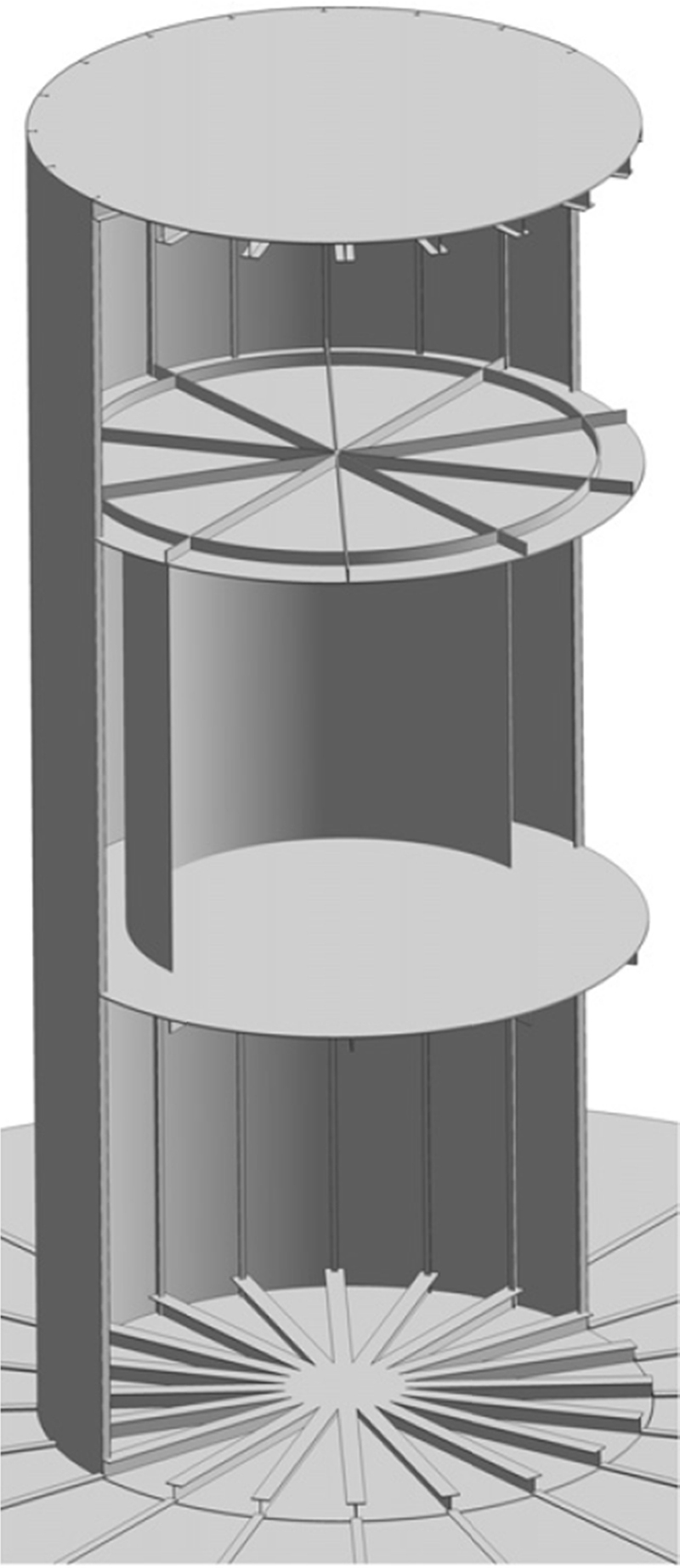
The next step taken was to carry out a detailed analysis of the Tri-floater structure, Fig. 11.2, investigating static and dynamic stability and potential mooring configurations. During this process the shell thickness was reduced from 20 to 15 mm by the inclusion of stiffeners, depicted in Fig. 11.3, as the dynamic analysis revealed that the original thickness resulted in an unnecessarily more costly structure. In this stage the actual diameters of the bracings were also derived, depicted in Fig. 11.4, such that the steel yield strength was not exceeded considering the relevant safety factors.
image
Figure 11.2 Structural components of the Tri-floater configuration (Lefebvre and Collu, 2012).
image
Figure 11.3 Illustration of column internal structure (Lefebvre and Collu, 2012).
In conjunction with the structural assessment, the hydrostatic stability carried out in the preliminary assessment was reiterated, now considering the refined structural composition of the support structure. Both intact and damaged scenarios were considered, although in the latter case it was assumed that the turbine would not be operational in such a scenario and hence a maximum allowable inclination angle of 20 degree was prescribed. In any case, the stability simulations produced inclination angles of 9 and 14.5 degrees for the intact and damage scenarios, respectively, well within the prescribed allowable inclination angles.
Likewise a hydrodynamic stability assessment was carried out, whereby numerical simulations were performed to derived the system RAOs and dynamic response in the operational and survival sea states. During initial hydrodynamic stability analyses it was seen that the system heave natural frequency was well within the range of most energetic wave spectrum frequencies, and to reduce heave motion, footplates were added to the bottom of each support column to augment the heave natural frequency, depicted in Fig. 11.2. Following the inclusion of the footplates, the system natural frequencies were found to be well outside the most energetic wave spectrum frequencies and that the maximum allowable inclination angles were not exceeded for either operational or survival sea states.
Finally, due to the relatively shallow water depth, a taut mooring system was considered. Both a three-line and nine-line mooring system were considered, and using the hydrodynamic analysis, the line length, pre-tension and stiffness were tuned such that the above requirements were still met, in addition to the requirement that line elongation must not exceed 10%. As both systems satisfied the requirements, the three-line system was adopted as the nine-line system was significantly more costly.
image
Figure 11.4 Bracings dimensions (Lefebvre and Collu, 2012).

11.5. Future trends

11.5.1. Size 10 MW and beyond

The size of the offshore wind turbine has been constantly increasing over the years, as, in general, the higher the rated power of the wind turbine, the lower is the final LCOE (Ashuri, 2012).
While there are already commercially available wind turbines with a rated power of 8 MW,4 wind turbines with a rated wind power equal to 10–12 MW and beyond are already being studied and developed (INNWIND FP7 project,5 HiPRWind FP7 project6). This trend is certainly going to continue, with some of the most current ambitious projects looking at 15–20 MW rated power offshore wind turbines, even if for HAWT there are some indications that it will be more and more difficult to upscale these systems (Tjiu et al., 2015).

11.5.2. Vertical and horizontal axis wind turbines

Whilst HAWTs have been the preferred configuration for onshore wind turbines, due to the significantly different conditions experienced in the floating offshore environment, other wind turbine configurations may be more advantageous from both technical and economic aspects.
There is a re-emerging interest in VAWTs for floating foundation applications, due to several potential advantages. This led to a number of studies being performed for this class of turbine by different researchers (Shires, 2013).
Nonetheless, there have been only a few research attempts to quantitatively compare HAWTs and VAWTs for floating offshore applications. Borg and Collu (2015) focused on comparing the static and dynamic responses of floating HAWT and VAWT systems. It was shown how a VAWT configuration can be characterised by a smaller inclining moment, a lower wind turbine mass and a lower wind turbine G, all factors that can be exploited to lower the cost of the support structure, and therefore the final LCOE. Nonetheless, the highly oscillatory nature of the aerodynamic forces acting on a VAWT system are also highlighted, bringing different challenges to the design of these wind turbines.
Referring to Section 11.3.1, VAWT wind turbines, even though they are commercially less mature than HAWTs, still have the opportunity to adopt an integrated design approach (wind turbine + support structure) from the early phases, ensuring that the optimisation process can investigate solutions modifying both the support structure and the wind turbine design. This should allow a substantial reduction of the LCOE.

11.5.3. Multipurpose platform integration

In some cases, future floating wind turbines may be integrated with other energy-harvesting devices, such as wave and tidal, as well as other ocean uses such as aquaculture. The main perceived benefit of integrating such different technologies is that infrastructure such as electrical grid connections, power conversion equipment and floating support structures can be shared, thereby reducing the cost of energy.
There have been a number of initiatives to investigate such integrated designs; H2OCEAN (www.h2ocean-project.eu), TROPOS (www.troposplatform.eu) and MERMAID (www.mermaidproject.eu) projects assessed the feasibility of multipurpose platforms; the MARINA project (www.marina-platform.info), Aubault et al. (2009), Roddier and co-workers (Peiffer et al., 2011), Floating Power Plant (www.floatingpowerplant.com) and Borg et al. (2013) are several examples of investigations into combined wind–wave energy-harvesting devices; and the SKWID (www.modec.com/fps/skwid) concept combined wind and tidal current energy extraction.
The main challenge is carrying out an integrated engineering and logistical design of such complex systems to provide competitive products.

11.5.4. Toward an integrated multi-disciplinary design and optimisation

Wind turbines, and especially offshore floating wind turbines, can be considered complex systems, similar in complexity to aeroplanes, cars and ships.
The design, analysis and optimisation of these complex systems require a multi-disciplinary approach. Multidisciplinary design, analysis and optimisation (MDAO) is an engineering field focussing on the use of numerical tools for the design of systems involving a number of disciplines or sub-systems. The main reason for MDAO is that such systems cannot be optimally designed by designing, analysing and optimising separately the several sub-systems, but it is necessary to take into account their interactions (Martins and Lambe, 2013).
MDAO was firstly applied for aircraft wing design, due to the strong coupling between the aerodynamics, structural, and control aspects of the problem. It has then been extended to complete aircraft and other engineering systems (eg, bridges, buildings, railway cars, automobiles, spacecraft, etc.) (Martins and Lambe, 2013).
In recent years, the first studies to apply an MDAO approach to wind turbines have been presented (Fuglsang and Madsen, 1999; Fuglsang et al., 2002; Kenway and Martins, 2008), for onshore and offshore fixed foundation wind turbine systems. Furthermore, the first open-source programs are becoming available. FUSED-Wind (http://www.fusedwind.org/) is: ‘an open-source framework for multi-disciplinary optimisation and analysis (MDAO) of wind energy systems, developed jointly by DTU and NREL’. NREL-WISDEM (https://nwtc.nrel.gov/WISDEM) is ‘built on top of the FUSED-Wind software framework and includes wrappers for a full suite of wind plant models including turbine aerodynamics, component structural analysis, component costs, plant balance of station costs, plant operations and maintenance costs, financial models, wind plant layouts, and wind turbine aeroelastic simulations’.
Multidisciplinary design, analysis, and optimisation approaches will play a fundamental role to lower the costs of offshore (fixed and floating) wind structures in the near future.

Nomenclature

B   Centre of buoyancy
C55,moor   Rotational stiffness coefficient (pitch) due to the mooring stiffness (Nm/rad)
C55,tot   Total rotational stiffness (pitch) (Nm/rad)
CP(env)   Centre of pressure of environmental forces
d.o.f.   Degree of freedom
F   Centre of flotation
FB   Buoyancy force (N)
Fenv   Sum of environmental forces (wind and current) (N)
Fmoor,V   Vertical component of the total force due to the mooring system (N)
G   Centre of gravity
M   Total mass (kg)
FOWT   Floating Offshore Wind Turbine
Ixx   Second moment of the waterplane area in roll (m4)
Iyy   Second moment of the waterplane area in pitch (m4)
MI   Inclining moment (Nm)
MLA   Centre of mooring force line action
MR,roll   Restoring moment in roll (Nm)
MR,pitch   Restoring moment in pitch (Nm)
RAOi   Response Amplitude Operator (m/m), i-th d.o.f. (i = 1,2,3) (m/m), Response Amplitude Operator, i-th d.o.f. (i = 4,5,6) (deg/m)
TLP   Tension Leg Platform
V   Displaced volume (m3)
X   Horizontal axis of reference (m)
Y   Lateral axis of reference (m)
Z   Vertical axis of reference (m)
zCP(env)   Vertical coordinate of CP(env) (m)
zMLA   Vertical coordinate of MLA (m)
θ   Angle of inclination (deg)
ρ   Seawater density (kg/m3)

Sources of further information

As previously mentioned, specific guidelines, recommended practices and certification documents are starting to be issued by the main classification and certification societies, and will probably be updated regularly. DNV GL, ABS and BV documents are freely available.
There are several international peer-reviewed conferences with sessions specifically focused on FOWT, the most important being the conferences organised by the European Wind Energy Association (EWEC and EWEA offshore), the ASME International Conference on Ocean, Offshore and Arctic Engineering (OMAE), and the conference organised by the International Society of Offshore and Polar Engineers (ISOPE).
At the moment there are no books specifically dedicated to offshore floating wind turbines, but there are a number of books that can be taken as references for offshore floating wind turbine support structures, and here only a few examples are given (with the caveat explained in Section 11.3.2): ‘Handbook of offshore engineering’ (Chakrabarti, 2005), ‘Offshore Hydromechanics’ (Journée and Massie, 2001), ‘Dynamics of Offshore Structures’ (Patel, 1989).

References

ABS. Guide for Building and Classing Floating Offshore Wind Turbine Installations. 2013.

Ashuri T. Beyond Classical Upscaling: Integrated Aeroservoelastic Design and Optimization of Large Offshore Wind Turbines. Delft University of Technology; 2012. Available at: http://mdolab.engin.umich.edu/content/beyond-classical-upscaling-integrated-aeroservoelastic-design-and-optimization-large (accessed 01.12.14.).

Aubault A, Cermelli C, Roddier D. WindFloat: a floating foundation for offshore wind turbines part III: structural analysis. Engineering. 2009:1–8.

Blue H. Blue H – Concept. 2004. Available at: http://www.bluehgroup.com/concept/index.php (accessed 25.02.15.).

Blue H. Blue H – Products – Phase 1. 2004. Available at: http://www.bluehgroup.com/product/phase-1.php.

Borg M, Wang K, et al. A comparison of two coupled model of dynamics for offshore floating vertical axis wind turbines (VAWT). In: Proceedings of the ASME 2014 33rd International Conference on Ocean, Offshore and Arctic Engineering OMAE 2014. San Francisco, CA: ASME; 2014.

Borg M, Collu M. A comparison between the dynamics of horizontal and vertical axis offshore floating wind turbines. Philosophical Transactions of the Royal Society A. 2015;373(2035).

Borg M, Collu M. Frequency-domain characteristics of aerodynamic loads of offshore floating vertical axis wind turbines. Appl. Energy. 2015;155:629–636.

Borg M, Collu M. Offshore floating vertical axis wind turbines, dynamics modelling state of the art. Part III: hydrodynamics and coupled modelling approaches. Renewable and Sustainable Energy Reviews. 2014;46:296–310. Available at: http://www.sciencedirect.com/science/article/pii/S1364032114009253 (accessed 01.12.14.).

Borg M, Collu M, Brennan F.P. Use of a wave energy converter as a motion suppression device for floating wind turbines. Energy Procedia. 2013;35:223–233. Available at: https://nbl.sintef.no/project/DeepWind 2013/Deepwind presentations2013/E/Borg.M._Cranfield Univ.pdf (accessed 18.11.13.).

Borg M, Collu M, Kolios A. Offshore floating vertical axis wind turbines, dynamics modelling state of the art. Part II: mooring line and structural dynamics. Renewable and Sustainable Energy Reviews. 2014;39:1226–1234. Available at: http://www.sciencedirect.com/science/article/pii/S1364032114005747 (accessed 03.11.14.).

Borg M, Shires A, Collu M. Offshore floating vertical axis wind turbines, dynamics modelling state of the art. Part I: aerodynamics. Renewable and Sustainable Energy Reviews. 2014;39:1214–1225. Available at: http://www.sciencedirect.com/science/article/pii/S1364032114005486 (accessed 01.12.14.).

Bulder B.H. Study to Feasibility of and Boundary Conditions for Floating Offshore Wind Turbines (Studie naar haalbaarheid van en randvoorwaarden voor drijvende offshore windturbines). 2002.

BV. Classification and Certification of Floating Offshore Wind Turbines, Bureau Veritas. 2010.

Chakrabarti S.K. Handbook of Offshore Engineering. Structure, I. 2005:2005–2006. Available at: http://books.google.com/books?hl=en&lr=&id=Snbuzun9LUQC&oi=fnd&pg=PP2&dq=HANDBOOK+OF+OFFSHORE+ENGINEERING&ots=vceQzo3Fnx&sig=LgsOQlU5AvXIOAHYJ8F2k4SV2To.

Collu M, et al. A comparison between the preliminary design studies of a fixed and a floating support structure for a 5 MW offshore wind turbine in the North Sea. In: RINA Marine Renewable and Offshore Wind Energy. 2010.

Cordle A, Jonkman J.M. State of the art in floating wind turbine design tools. In: ISOPE 2011 Conference. 2011:367–374.

DNV. DNV-OS-J103 Design of Floating Wind Turbine Structures. 2013.

DNV GL. PROJECT FORCE – Offshore Wind Cost Reduction Through Integrated Design. 2013.

Driscoll F, et al. Validation of a FAST model of the statoil hywind demo floating wind turbine. In: Proceedings of the ASME 2015 34th International Conference on Ocean, Offshore and Arctic Engineering. St. John's, Newfoundland, Canada. 2015:1–10.

Ferreira C.S, et al. Comparison of aerodynamic models for vertical Axis wind turbines. Journal of Physics: Conference Series. 2014;524(1):012125. Available at: http://stacks.iop.org/1742-6596/524/i=1/a=012125 (accessed 01.12.14.).

Fuglsang P, Bak C, Schepers J. Site-specific design optimization of wind turbines. Wind Energy. 2002;5:261–279. Available at: http://onlinelibrary.wiley.com/doi/10.1002/we.61/abstract (accessed 01.12.14.).

Fuglsang P, Madsen H. Optimization method for wind turbine rotors. Journal of Wind Engineering and Industrial Aerodynamics. 1999;80(1–2):191–206. Available at: http://www.sciencedirect.com/science/article/pii/S0167610598001913 (accessed 01.12.14.).

Van Hees M, et al. Study of Feasibility of and Boundary Conditions for a Floating Offshore Wind Turbines. 2002.

IEC. IEC 61400-3, Wind Turbines – Part 3: Design Requirements for Offshore Wind Turbines. 2007.

ITTC. ITTC Wiki. 2014. Available at: http://www.ittcwiki.org/doku.php.

Jonkman J. Definition of the Floating System for Phase IV of OC3. 2010. Available at: http://www.nrel.gov/docs/fy10osti/47535.pdf (accessed 02.12.14.).

Jonkman J.M. Dynamics Modeling and Loads Analysis of an Offshore Floating Wind Turbine. ProQuest; 2007. Available at: http://books.google.com/books?hl=en&lr=&id=66F_VT7Px-kC&oi=fnd&pg=PA1&dq=Dynamics+Modeling+and+Loads+Analysis+of+an+Offshore+Floating+Wind+Turbine&ots=N9lpZfiBw1&sig=0lbYYU9zsz1HrcfoCVBt3leCYFs (accessed 10.02.12.).

Jonkman J.M, et al. Offshore code comparison collaboration within IEA wind task 23 : phase IV results regarding floating wind turbine modeling. In: EWEC. 2010.

Jonkman J.M, Matha D. Dynamics of offshore floating wind turbines — analysis of three concepts †. Wind Energy. 2010.

Journée J, Massie W.W. Offshore Hydromechanics. TU Delft, 2000. 2001.

Kenway G, Martins J. Aerostructural shape optimization of wind turbine blades considering site-specific winds. In: Proceedings of 12th AIAA/ISSMO Multidisciplinary Analysis and Optimization Conference. 2008. Available at: http://arc.aiaa.org/doi/pdf/10.2514/6.2008-6025 (accessed 01.12.14.).

Larsen T, Hanson T. A method to avoid negative damped low frequent tower vibrations for a floating, pitch controlled wind turbine. Journal of Physics: Conference Series. 2007;75(1):012073. Available at: http://iopscience.iop.org/1742-6596/75/1/012073 (accessed 01.12.14.).

Laura C.-S, Vicente D.-C. Life-cycle cost analysis of floating offshore wind farms. Renewable Energy. 2014;66:41–48. Available at: http://www.sciencedirect.com/science/article/pii/S0960148113006642.

Lee K.H. Responses of Floating Wind Turbines to Wind and Wave Excitation. Massachusetts Institute of Technology; 2005.

Lefebvre S, Collu M. Preliminary design of a floating support structure for a 5 MW offshore wind turbine. Ocean Engineering. 2012;40:15–26.

Martins J, Lambe A. Multidisciplinary design optimization: a survey of architectures. AIAA Journal. 2013;51(9). Available at: http://arc.aiaa.org/doi/abs/10.2514/1.J051895 (accessed 01.12.14.).

Merz K.O, Svendsen H.G. A control algorithm for the deepwind floating vertical-axis wind turbine. Journal of Renewable and Sustainable Energy. 2013;5(6):063136. Available at: http://scitation.aip.org/content/aip/journal/jrse/5/6/10.1063/1.4854675 (accessed 01.12.14.).

Myhr A, et al. Levelised cost of energy for offshore floating wind turbines in a life cycle perspective. Renewable Energy. 2014;66:714–728. Available at: http://linkinghub.elsevier.com/retrieve/pii/S0960148114000469.

Patel M.H. Dynamics of Offshore Structures. Butterworth-Heinemann Ltd; 1989.

Paulsen B.T, et al. Forcing of a bottom-mounted circular cylinder by steep regular water waves at finite depth. Journal of Fluid Mechanics. 2014;755:1–34. Available at: http://journals.cambridge.org/abstract_S0022112014003863 (accessed 01.12.14.).

Paulsen U, et al. Outcomes of the DeepWind conceptual design. In: 12th Deep Sea Offshore Wind R&D Conference. Trondheim, Norway. 2015.

Peiffer A, Roddier D, Aubault A. Design of a point absorber inside the WindFloat structure. In: Ocean Space Utilization; Ocean Renewable Energy. Volume 5. ASME; 2011:247–255. Available at: http://proceedings.asmedigitalcollection.asme.org/proceeding.aspx?articleid=1624862 (accessed 01.12.14.).

Principle Power. WindFloat Prototype. 2012. Available at: http://www.principlepowerinc.com/products/windfloat.html.

Robertson A, et al. Summary of conclusions and recommendations drawn from the DeepCWind scaled floating offshore wind system test campaign. In: ASME 2013 32nd International Conference on Ocean, Offshore and Arctic Engineering. Nantes, FR: ASME; 2013.

Sclavounos P.D. Nonlinear impulse of ocean waves on floating bodies. Journal of Fluid Mechanics. 2012;697:316–335. Available at: http://journals.cambridge.org/abstract_S0022112012000687 (accessed 01.12.14.).

Shires A. Design optimisation of an offshore vertical axis wind turbine. Energy. 2013;166(EN1):7–18. Available at: http://www.icevirtuallibrary.com/content/article/10.1680/ener.12.00007 (accessed 29.12.13.).

Statoil. Hywind Demo. 2010. Available at: http://www.statoil.com/en/TechnologyInnovation/NewEnergy/RenewablePowerProduction/Offshore/Hywind/Pages/HywindPuttingWindPowerToTheTest.aspx?redirectShortUrl=http://www.statoil.com/hywind.

Tjiu W, et al. Darrieus vertical axis wind turbine for power generation II: challenges in HAWT and the opportunity of multi-megawatt darrieus VAWT development. Renewable Energy. 2015;75:560–571. Available at: http://www.sciencedirect.com/science/article/pii/S0960148114006661 (accessed 01.12.14.).

Wayman E.N, et al. Coupled dynamic modeling of floating wind turbine systems. In: Offshore Technology Conference. Houston, Texas. 2006.


1 Response Amplitude Operators.

2 Whilst verification and validation are sometimes used interchangeably, verification is the process of verifying that the numerical model has been correctly implemented (‘solving the equations right’), and validation is confirming that the implemented numerical model actually represents what occurs in reality (‘solving the right equations’).

3 It has to be said that the floating wind turbine ‘WindFloat’ was the first prototype of its kind, a one-off production, and therefore the CAPEX/MW reported here cannot be considered to represent the likely CAPEX/MW of the same configuration at a commercial mature stage.

4 http://www.mhivestasoffshore.com/Products-and-services/The-Turbines/V164.

5 http://www.innwind.eu/.

6 http://www.hiprwind.eu/.

..................Content has been hidden....................

You can't read the all page of ebook, please click here login for view all page.
Reset
3.139.80.209