
13
Cabling to connect offshore wind turbines to onshore facilities
Abstract
This chapter presents a review of general aspects and practical challenges of subsea power cables for offshore wind farm applications. Interarray, interplatform and export cables are key components which require careful analysis and design in view of their mechanical properties, electrical voltages and installation methodologies. Some lifecycle cost savings related to offshore cables are discussed, including the use of higher-voltage cables, the layout optimization of interarray cables, the post-lay burial activities, the cable burial depth identifications and the J-tubeless interfaces. For offshore floating wind turbines and substations in deeper waters, the dynamic cable concepts are proposed along with discussion of some environmental impacts due to waves, currents and on-bottom dynamic stability. The outlook for offshore wind farm cables is provided, with a list of potential innovative cabling technologies of current industrial interest.
Keywords
Cable installation; Cabling technology; Dynamic cable; Export cable; Interarray cable; J-tube; Offshore wind farm; Renewable energy; Wind turbine13.1. Introduction
Cabling systems play a vital role in integrating an offshore wind farm into a national grid or electricity transmission network by conveying a vast amount of electricity over a long distance to thousands of homes and millions of people. The cabling industry has experienced significant growth over the years as demand for subsea cables is growing steadily. Many countries make commitments to offshore renewable wind energy and interconnect to their national grids. As more projects of offshore wind farms in deeper waters with variable environmental conditions are proposed to improve the financial return, advanced cabling technology is required to develop higher-capacity and larger-diameter power cables.
For safe and cost-efficient energy transmission, subsea cable layouts must be optimized, depending on the desired wind turbine locations, offshore and onshore infrastructures, geophysical and geotechnical properties. In light of the international commitments to significantly increase offshore wind capacity, the interarray and export cabling systems have been identified by the offshore wind industry as ones of the key areas where related cost savings should be considered. In practice, the capital expenditures can be reduced by increasing the cable voltage levels. For a specific wind farm, the lifecycle cost reductions, particularly for interarray and export cables, can be further achieved through the cable installation procedure, sequence and failure prevention. These are controlled by several influential factors, including the offshore wind farm and coastline architecture, water depth, wind turbine size, fixed or floating foundation substructure type, environmental sea state and seabed conditions, and the arrangement of construction, transportation and installation (Department for Business Enterprise & Regulatory Reform, 2008).
This chapter is devoted to a review of general and practical aspects of offshore wind farm cables, current technical challenges, potential technology developments and innovations to minimize cable installation costs, damage rates and hence insurance costs. Some theoretical background and analysis formulae are provided with attention being paid to the global structural mechanical behaviours of flexible cables rather than their electrical, manufacturing or material counterparts which can be found in other excellent textbooks (Burton et al., 2011; Worzyk, 2009) and recognized offshore standards (DNV, 2012, 2014).
13.2. Offshore wind farm cables
An offshore wind farm consists of a number of wind turbine generators, substructures and supporting foundations which need to be appropriately positioned to minimize the overall operational costs and the energy loss due to the wind interference effect from upstream or nearby turbines. The impact on the environment must also be thoroughly assessed as was done, for example, for the Beatrice wind farm (2011). The electrical transmission system for offshore wind farm technologies includes interarray, interplatform and export cables of different specifications, offshore collector or substation and converter (if required) infrastructures. The key design mechanical parameters of cables with composite materials include outer diameters, dry and submerged weights, lengths, axial and bending stiffness, and end connections, apart from the dynamic properties such as natural frequencies, modal shapes and viscous damping coefficients. These are chosen variably, depending on the wind farm site physical and environmental characteristics, turbine rating and sizes, distribution network connection and operational voltages, polymeric insulation properties such as cross-linked polyethylene (XLPE) or ethylene propylene rubber (EPR), conductor materials (copper or aluminium) and cross-sectional areas, embedded fibreoptic communication control lines, external sheath protections and offshore routes to mainland facilities (Worzyk, 2009).
Fig. 13.1 illustrates different functions of offshore wind farm cabling systems for fixed and floating foundations. Tables 13.1–13.3 demonstrate properties including the approximated outer diameters and weights of some typical interarray (33 kV, AC), export HVAC (132 kV) and export HVDC (300 kV, bipole) cables, respectively.
13.2.1. Interarray cables
Interarray cables link several wind turbines to offshore substation platforms to allow the electricity generated from each turbine to be collected and transformed before being transmitted to onshore facilities. Within the turbine tower, each cable end is terminated onto the high-voltage switchgear, which is able to isolate cable failures and keep the remaining functioning parts of the turbine in operation. Cables between wind turbines are relatively short in length being approximately less than 1500 m, depending on the turbine rotor diameter (DR) and the minimum spacing requirement (typically more than 5DR–7DR) between the two turbine systems. However, those connecting turbines to the offshore substations could be longer and possibly up to 3000 m.
Interarray cables are typically three-core copper conductors with steel wire armoured and conductor/insulation screening components (Worzyk, 2009). The nominal operating voltage of the cable system is in the medium voltage range, ie, 33 kV. The 33-kV cable is traditionally the standard for offshore wind distribution, but a higher voltage cable (ie, 66 kV) is under investigation to be considered by the future offshore wind industry for larger wind farms with high wind turbine ratings (Ferguson et al., 2012). The higher voltage 66-kV cable with a smaller cross-section and lower current would allow for greater power capacity and a reduction of system power losses. In addition, a fewer offshore substations with significantly lighter transformers would be required with the potential cuts of overall cable component necessities. Together with the optimization of the wind turbine spacing and interarray cable layout, the higher-voltage transmission could offer lower lifecycle cost savings. By using aluminium conductors, costs might be further reduced by about a third. However, due to the lighter weight of aluminium, attention must be paid to the greater dynamic cable movement and a higher bending radius during the installation in water.

Figure 13.1 Offshore wind farm cables for fixed (a, b) and floating (c) wind turbines, substations (a–c) and converter (b, c) platforms.
Table 13.1
Example of interarray cable properties
| Details | Nominal cross-sectional area of conductor (mm2) | |||
| 95 | 120 | 185 | 240 | |
| Outer diameter (mm) | 104 | 106 | 114 | 119 |
| Weight (kg/m) | 16 | 18 | 21 | 23 |

Table 13.2
Example of interplatform cable properties
| Details | Nominal cross-sectional area of conductor (mm2) | |||
| 300 | 400 | 500 | 800 | |
| Outer diameter (mm) | 167 | 168 | 176 | 194 |
| Weight (kg/m) | 48 | 51 | 58 | 74 |

Table 13.3
Example of export cable properties
| Details | Nominal cross-sectional area of conductor (mm2) | |||
| 300 | 800 | 2000 | 3000 | |
| Outer diameter (mm) | 102 | 118 | 140 | 155 |
| Weight (kg/m) | 22 | 33 | 53 | 70 |

Recently, the UK Carbon Trust estimated that the use of 66-kV interarray cables could cut the cost of offshore wind energy by about 1.5% (Carbon Trust launch race for next generation of offshore wind cables, 2013). Accordingly, several manufacturers now aim to design, qualify and certify 66-kV cables to be integrated into relevant switchgears and transformers whose specifications are available at 66 kV.
13.2.2. Interplatform cables
A number of offshore collector platforms are typically required to gather power from wind turbine generators through interarray cables (see Fig. 13.1). To minimize the transmission loss versus increasing distance to shore, the step-up transformers located on the collector platforms are used to increase the cable voltage to the higher level (eg, 132 kV and higher). If the HVDC (high-voltage direct-current) export cables are desired for a wind farm located very far from the mainland (more than 60–100 km or 80 km on average), the electricity from the offshore collector platforms will be transmitted to a converter platform via the HVAC (high-voltage alternating-current) interplatform cables. The HVAC is converted into the HVDC with nominal voltage possibly up to ±525 kV (ABB launches world's most powerful cable system for renewables, 2014).
Both interarray and interplatform three-core cables are substantially similar, except for the thickness of the insulation layers and thus the resulting outer diameters which may be different (up to 250 mm for interarray cables and 300 mm for interplatform cables) according to the different carried voltages. For HVAC interplatform cabling, a single-core cable design may also be used. Fig. 13.2(a) illustrates a three-core copper XLPE 33-kV interarray cable. Fig. 13.3 presents a schematic cross-sectional structure of the three-core XLPE 66-kV cable proposed for the Fukushima offshore wind farm (Tominaga et al., 2014).
13.2.3. Export cables
The key function of offshore export cables is to efficiently transmit the electrical power with minimal loss from the offshore wind farm to the cable connection facility at the landfall point. Export cables may operate with HVDC (single-core) or HVAC (one- or three-core) technology, depending on several balancing factors, particularly the offshore distance to shore, the total generated power of the wind farm, material and operational costs. HVDC cables require both offshore (AC/DC) and onshore (DC/AC) converter stations, and the erection of an offshore converter station is fairly expensive. However, HVDC cables have greater advantages when a larger amount of power is transmitted over a long distance due to the power loss reduction as compared to the HVAC transmission as shown in Fig. 13.4 (Gevorgian and Hedrington, 2010). In addition, the HVDC system reduces cable quantities or constraints on supply and allows the transmission to better handle the occurrence of strong wind gusts.


The baseline offshore export cable design assumption is a pair of single-core HVDC cables (typically XLPE insulated and with copper conductor) for each converter platform, with a high positive and negative voltage relative to the earth. The two cables of each HVDC circuit and associated fibreoptic cables or health-monitoring sensors may be bundled together as a single unit and buried in the same subsea trench until they approach the landfall location. Alternatively, they can be installed separately, depending on the cable burial strategy and local seabed conditions. It is noted that the installation cost per km of a single bundle export link is considerably lower than that of individual cables. Fig. 13.2(b) illustrates a single-core HVDC export cable.
Based on a recent report summary towards the end of December 2014, there are currently 47 export cables for 21 offshore substations and 1309 wind turbines operating in UK waters (The Crown Estate, 2015a).
13.2.4. Cable layout and spacing
For known locations of offshore wind turbines which depend mainly on the prevailing wind direction and geotechnical properties, interarray cables are more constrained than interplatform and export cables in terms of the layout and spacing within a wind farm. From an economical viewpoint, the shortest routes (so-called strings) to the substation platforms for interarray cables should be wisely determined and optimized from the outset of any development plan by also taking into account several factors and risk-based assessments. At the present time, wind turbines in several offshore wind farms are spaced apart for a certain distance which can in turn influence the access of subsequent activities including cable (laying and burial) installation and turbine-substructure maintenance. Since local information and circumstances of different wind farms are site-specific, the cable layout and spacing analysis should be carried out on a case-by-case basis (United States Department of Interior Bureau of Safety and Environmental Enforcement (2014)).
Depending on the number of turbines per string, the number of strings, the substation and converter locations, and the export cable orientations within a wind farm, several subsea layouts of interarray cables can be proposed. The main categories may include the radial (open-loop), radial with branching, and ring (closed-loop) designs as shown in Fig. 13.5. With respect to the cable lengths, capital costs and operational power losses, the radial-branching networks may be more optimal than the radial ones for fixed wind turbine locations (Jenkins et al., 2013). In all layout cases, the use of 66-kV cables with possible aluminium conductors will potentially reduce capital costs for offshore cabling if higher bending radius can be accommodated.

13.3. Offshore cable installation, protection and challenges
Large offshore wind farms in deep waters experience several technical challenges and unexpected delays related to the installation activities of subsea cables. Recommendations and standardization of cable-laying burial techniques and sequences are needed to reduce the scheduling and operational costs. There are also risks associated with the cable transportation and installation which can affect the cable long-term performances. The financial, technical and insurance-related costs and potential damage to corporate reputations have significant implications. Offshore cables require diligent planning to minimize potential risks at an early design stage.
Typical key stages of offshore cable installation include the preinstallation survey, route clearance, cable laying and burial, and postinstallation assessment. To safeguard subsea cables from environmental hazards, offshore works normally take place outside the winter months, based on a 24-h basis and the cables are installed in narrow trenches (typically about 250 mm wide) or buried into the seabed at a predetermined depth depending on the soil conditions. Where cable burial is unfeasible (eg, near the wind turbine foundation) or insufficient (eg, due to the active seabed scour), reliable protection means should be alternatively considered and implemented. These include, for example, the use of controlled rock placements, rock dumping, preformed concrete mattresses, positioning of grout or gravel bags, ducting and use of sleeves (Beindorff and Baalen, 2013). Estimation of the installation time and cost related to cable installations can be found in Kaiser and Snyder (2012).
13.3.1. Preinstallation survey
Detailed preinstallation survey and mapping of offshore geotechnical, environmental, archaeological and meteorological conditions are essential to the selection of subsea cable routes, corridors, layouts, installation planning and methodologies. They are also useful for the identification of potential hazards and obstacles which can impact on the cable laying and burial operations. These include, for example, large rocks, wrecks, unexploded ordnances, areas near an aquaculture farm, and existing pipeline and cable infrastructures, especially in the North Sea regions. In general, a 500-m Advisory Safety Zone (ASZ) is requested around all installation vessels, while in the wind farm construction area a 50-m ASZ around each installed turbine is required. A 250-m ASZ is required along the export cable route (The Crown Estate, 2012).
For geotechnical explorations, the preinstallation frameworks may include the cone penetrometer, boreholes and vibrocore tests of soil samples at a maximum depth of 5 m below the mean seabed level, within a wind farm and along the potential export cable routes (Worzyk, 2009). Cable burial trials may also be conducted in advance to make sure that the desired burial equipment is appropriate for actual seabed conditions while achieving the burial depth requirements. Such trials should be planned and carried out through a certain length (eg, 1 km) covering different soil types.
From a geophysical standpoint, the location and mobility of sand waves along the cable route should be determined to assess whether such features could be avoided or, if impossible, whether seabed preparation or clearance is required to ensure the stable seabed character maintaining the burial depth index and without uncovering the buried cables in a short period of time.
13.3.2. Cable laying and burial practice
In practice, there are several approaches available for cable installation and the finally selected one would be based on overall data obtained from the preinstallation site investigations. For a large offshore wind farm such as the Dogger Bank Creyke Beck (FOREWIND, 2013), a combination of ploughing, jetting and trenching may be considered for cable installation, depending on the water depth, seabed condition and level of sedimentary variation along cable routes. In practice, the interarray cabling operation would take place before the export one. For export cables, the installation may start from the wind farm towards shore or in the opposite direction. The most common wind farm cable-laying and burial philosophy may be largely classified as follows.
13.3.2.1. Simultaneous lay and burial
The laying and burial operations are coupled. Cables are laid by a turntable and buried simultaneously with burial equipment, such as a plough, being towed by a self-propelled large vessel or spread-moored barge, cutting a narrow trench, lifting the soil out of the trench and then backfilling over the laid cables. This continuous operation is typically considered for long export cables because of their lengths and heavy weights.
The main advantage of this coupled laying-burial method is minimized risks to the cable from exposure. However, this system requires synchronized control of lay and burial factors as well as a large and more reliable weather window such as in the summer, with the laying effectiveness being naturally governed by the burial speed. A slow burial process would hence slow down the entire laying operation and this is particularly costly for a high day-rate, which could be as high as £200,000 a day, of a specialized large cable payload vessel used for the cable deployment. In addition, the ploughing performance achieving the target burial depth is dependent on the plough equipment geometry and seabed conditions with a very stiff clay or dense sand providing greater challenges. For very stiff and bedrock-type seabed layers, modern mechanical trenchers may be alternatively used.
Delay in laying subsea cables can lead to rising operational costs, as seen from the Lewis Wind Farm in the Western Isles where delays in cable laying or assessing the cable business case have been blamed, resulting in a withdraw of the project plan (Lewis wind farm backer pulls out over cable delay, 2014).
13.3.2.2. Post-lay burial
The laying and burial operations are decoupled. Cables are laid separately in advance by a cable-laying vessel and they are subsequently buried by a separate dynamically positioned vessel using, for example, a high-pressure water jetting combined with a remotely operated vehicle (ROV) tracking system.
The post-lay burial method has the advantage of the laying operation being able to be completed more rapidly with the slower burial being performed independently and at a convenient time. This cable burial operation can be done by a lower day-rate vessel. However, hazards may arise when the cable is left unprotected for some time on the seabed. These can lead to cable lateral and vertical movements, the so-called on-bottom stability, or damage due to the penetration of fishing gear and drag anchor during the bottom-trawling and vessel-positioning activities. Therefore, if the post-lay burial solution is used for reducing the installation time and cost, the period of cable exposure should be limited (ie, within a few hours) and a guard vessel should be deployed patrolling the cable route to warn fishing boats. It is crucial that the fishermen are informed of unburied cables which may pose a risk to their fishing activities. As realized from the Greater Gabbard offshore wind farm, problems with unburied cables covered with improperly laid subsea mattresses have been criticized by fishermen (Greater Gabbard OWF's Cabling Infrastructure Worries Local Fishermen, 2014).
An example of the post-lay burial method is the Gwynt y Mor Offshore Wind Farm project. There are four HVAC export cables with the copper conductor, XLPE insulation, 132-kV nominal voltages and an average length of 21.3 km. In addition, there are 161 interarray XLPE copper 33-kV cables with a total length of 148 km (Gwynt y Môr cabling complete, 2015).
13.3.3. Cable burial depth identification
One of the challenging aspects for offshore wind farm cables is to identify the minimum burial depth which can provide long-term safe protection of subsea cables against any underwater hazards or threats such as trawling, fishing gear and ship anchoring throughout their operational lifetime. This is important because the damage, integrity loss or fault of the cabling system is difficult to repair and the associated energy losses and insurance claims can be significant. Depending on the seabed condition and the level of protection or hazard type, the burial depth of several wind farm cables is typically in the range of 0.5–2 m following a detailed burial risk assessment and the widely recognized ‘Burial Protection Index’ (BPI) based on the real ploughing database and developed originally for fibreoptic telecommunication cables (Mole et al., 1997).
Recently, the Carbon Trust's Offshore Wind Accelerator (OWA) joint industrial programme has published recommendations for a new optimization-based Cable Burial Risk Assessment (CBRA) methodology to determine the cable optimal and minimum ‘Depth of Lowering’ (DoL), which is practically and economically acceptable from a cable protection viewpoint based on the probability of attack (eg, due to an anchor) on the cable (Carbon Trust, 2015). Generally speaking, the CBRA method is intended to reduce the conservatism and uncertainties in the use of a significant burial depth normally required by stakeholders or operators. Depending on the site updated survey data, the CBRA method can be used several times during the wind farm development from design, routing, trenching, laying and decommissioning, and should be used independently for interarray and export cables. Fig. 13.6 shows the definition of the trench minimum versus target DoL suggested by the CBRA method and the cable installer, respectively. It is noted that because of a lower DoL suggested by the CBRA method, the overall cost of cable installation can be reduced.
13.3.4. J-tube and J-tubeless interface
Each end of the interarray, interplatform and export cables is typically connected to the wind turbine generators, substation or converter platforms through the so-called J-tube entry and interface system (DNV, 2014). This steel conduit with a nearly ‘J’ shape may be placed inside or outside the foundation substructure (monopile, jacket, gravity base or tripod) with position being fixed (inside and outside the tube) or adjustable with respect to the optimal height and angle (outside the tube). The J-tube path runs vertically from the cable termination or hang-off point at the tower base above sea level down to the seabed bottom and has an outward opening bellmouth where the cable is pulled through by means of a messenger wire and winch. To guarantee a smooth transition without damage and ripping of the cable during the pull-in operation, the bellmouth radius should be larger than the cable minimum bending radius (MBR). Fig. 13.7 displays the standard J-tube and J-tubeless systems of a monopile and jacket foundation.


The number and size of J-tubes required for each wind turbine and substation depend on the wind farm capacity and subsea cable layouts. Two J-tubes are normally found for turbine generators. For cable interlaying between the two end J-tubes, the cable part close to the second end should be laid with a greater slack condition to allow for additional movement or stretching. For a single large J-tube accommodating several cables, for example, to a substation platform, the thermal and heat condition within the crowded tube should be given special attention. To replace the requirement for costly steels and their lifetime corrosions, a J-tube with composite materials may be designed and implemented.
To reduce the cable installation time and cost by eliminating the need for protective J-tubes and pull-in operations, a novel concept of a J-tubeless entry system has recently been introduced to modern offshore wind farms. Because the cable suspended from the hang-off location is flexible and susceptible to movement, this J-tubeless system should be internally routed inside the wind turbine substructure to avoid the dynamically environmental impact from waves and/or currents. The feasibility, benefit and risk of a free-hanging cabling design should be carefully explored with respect to the cable dynamics to fully understand the mechanical fatigue versus electrical testing results and determine realistic capital and operational costs versus the potential impact on the wind farm development schedule.
For both J-tube and J-tubeless interfaces, the subsea protection of a free-spanning section (typically about 20 m long) outside the wind turbine foundation of an interarray cable is needed. This protection is normally based on the recognized techniques including the use of rock dumping (also for scour protection), concrete mattresses plus sandbags, and the inflatable grout bags, some of which requiring diver intervention or assistance. For a zero-diver operation, the static or dynamic bend restrictors may be implemented by utilizing a heritage of standards from the oil and gas industry. A series of bend restrictors control and protect the cable from the variation of MBR or overbending during the installation and operation.
13.4. Dynamic cables for floating wind turbines and substations
For offshore floating wind turbines, attention must be paid to the development, design and optimization of a robust dynamic power cable which requires a high level of flexibility, compliance with a floater motion and fatigue resistance subject to dynamic environments. The combined effects of waves, currents, seabed touchdown interactions and top-end floater movements on the cable connected to a floater are critical. These need to be fully investigated via a global fluid–structure interaction and multibody coupling model together with the experimental tests.
Resembling offshore risers used in the oil and gas applications for transporting fluids from the seabed wells to the platforms (Bai and Bai, 2014), potential configurations for floating turbine or platform cables are displayed in Fig. 13.8 which includes the so-called ‘W’ (Fig. 13.8(a)) and lazy wave (Fig. 13.8(b)) shapes. The latter concept has recently been considered for some floating wind turbines such as the Statoil Hywind (Offshore wind farms: Floating solutions for deep-water cables, 2010) and those applied to the Fukushima offshore wind farm (Tominaga et al., 2014).

The W-type cable may be used for connecting between the two floating wind turbines or between the floating substation and wind turbines, whereas the lazy wave cable may be used as an interarray, interplatform and export cable. In any case, there is a requirement for a design of buoyancy modules (typically made of synthetic foams) to be distributed along a certain mid-water part of the cable. Secure fastening and precise positioning of buoyancy modules are ensured by using internal clamps. The use of such distributed buoyancy is mainly aimed at minimizing the overall cable dynamic responses and accommodating the cable dynamic tension or curvature changes in harsh weather conditions, by decoupling the platform motion from the cable touchdown point at the seabed. Since the W or wave cable configuration is significantly controlled by the change of additional buoyancy, designers must accurately estimate the buoyancy particulars such as the diameter, submerged weight (density) and spacing: these should be maintained throughout the lifetime operations by avoiding any buoyancy loss and/or slippage.
Fig. 13.9 displays the effect of buoyancy change on the overall configurations of lazy wave cables manifesting different hang-off, arch bend and touchdown catenaries. Depending on the hang-off angle, water depth, platform offset, footprint and soil stiffness, areas of local maximum static tensions typically occur at the hang-off point and the two ends (ie, lift and drag points) of the distributed buoyancy portion, whereas areas of local maximum static bending moments correspond to the sagging, hogging and touchdown areas where maximum curvatures occur. These parameters should be systematically verified through a cable shape sensitivity study. Nevertheless, in practice there are some other effects such as the mean drag force and its direction owing to the combination of wave and current, marine growth and installation imperfection (eg, due to the water absorption or ingress to a buoyancy module) which can lead to variable or uncertain hydrodynamic (normal and tangential) drag coefficients to be used in the design of non-uniform cable sections in comparison with the bare sections. These effects have to be accounted for using a more sophisticated finite element or computational fluid-structural dynamics software.

The free-hanging dynamic cable also requires a special protection at the platform hang-off location and seabed end termination using, for example, a bend stiffener or restrictor to avoid high local bending stresses leading to the increased fatigue damage of the cable (Bai and Bai, 2014).
13.5. Some mechanical aspects of subsea cables
Cable is a one-dimensional structure being inherently flexible, having a high slenderness, high aspect (length-to-diameter) ratio, high axial but lower bending rigidity. Three-dimensional large cable displacements and associated axial or bending stresses can be induced by different environmental loading during operational phases (Srinil, 2004). Therefore, it is of practical importance to understand some fundamental properties and mechanical aspects of cable structures installed at sea and connecting different support structures. To evaluate cable static and dynamic behaviours as well as fatigue, there are several models, formulae and governing (eg, thermal, electrical, mechanical, boundary condition) factors to be parametrically considered during the early stage analysis and design of subsea cables. Herein, some of the key mechanical and global structural analyses are discussed with reference to Fig. 13.10.
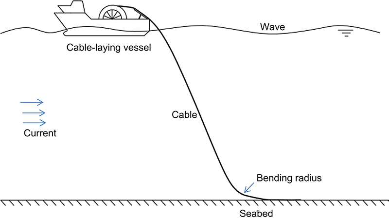
13.5.1. Catenary configuration
A single-span cable shape during the laying operation may be described based on a simple catenary theory, as shown in Fig. 13.10, which assumes that the cable configuration only depends on its own effective weight per length in water (w) and axial tension (T). The effects of static deformation, bending moment and drag force are neglected as they may be considered to be of secondary importance. By further assuming a zero tangential slope at the cable seabed touchdown, a horizontal tension component (TH) is thus a constant and equal to the seabed bottom tension. Accordingly, the Cartesian x-y coordinates along the arc length (s) can be derived as (Berteaux, 1976)
![]() [13.1]
[13.1]
![]() [13.2]
[13.2]
13.5.2. Minimum bending radius (MBR)
During the cable vertical laying operation, the maximum bending stress normally occurs near the seabed where the minimum radius (maximum curvature) occurs. Using a linear moment–curvature relationship and Eqs. [13.1] and [13.2], the minimum bending radius (MBR) at the seabed may be simply approximated as
![]() [13.3]
[13.3]
Alternatively, if the total length (L) and vertical location of the hang-off or laying point (H) of the cable is known, it may also be approximated that
![]() [13.4]
[13.4]
For a horizontally radial laying operation where a straight-line laying approach is not feasible due to, eg, an obstacle, Worzyk (2009) suggested, by introducing a safety factor of two and the cable-soil lateral friction coefficient μ, that
![]() [13.5]
[13.5]
13.5.3. Laying tension and hang-off angle
As the cable is being laid vertically from the vessel, the cable tensile force at the laying wheel (TL) may be approximated as
![]() [13.6]
[13.6]
Correspondingly, the departure or hang-off angle with respect to the horizontal level at the laying wheel may be approximated in different ways as
![]() [13.7]
[13.7]
13.5.4. On-bottom stability
In shallow water with a high energetic environment, it may be necessary to understand the on-bottom stability of interarray cables being laid on the seabed prior to the post-lay burial operation which is aimed at cable installation cost reduction. For a certain period of time, how much the unburied cable laterally or even vertically displaces is checked when subject to the hydrodynamic lift and drag loading from the combined wave and current against the soil resistance and cable weight in water. In practice, the cable on-bottom stability may be preliminarily verified following the DNV-RP-F109 guidelines (2007) which have been developed specifically for pipeline installations in deep waters. Two relevant approaches are the absolute and generalized lateral stability which allow zero and certain (up to 10 diameters) displacements of the cable, respectively.
In DNV-RP-F109, the specific weight of a pipe required for obtaining the stability is very much dependent on the pipe diameter. The design curves for the generalized stability are obtained from a large number of one-dimensional dynamic analyses, ie, on the flat seabed by neglecting bending and axial deformation of the pipe. In comparison with the pipelines (eg, 24–42 in. diameters and 489 kg/m submerged weight for the 24-in. pipe), the diameter and unit weight of the cables are much smaller (eg, up to 11–13/16 in. for export cables and 68 kg/m submerged weight for a 132-kV HVAC cable); thus, cables are more flexible. In addition, as wind farms are presently located in shallow waters, the effects of hydrodynamic loads on subsea cables are very significant.
Depending on the weather and soil conditions, spatial and temporal movements of subsea cables are fairly complicated and it may be too conservative to achieve the stability requirement when using the pipeline design code. The dynamic stability method is needed to understand actual physical mechanisms based on the cable–soil–fluid interaction modelling and dynamic investigation.
13.5.5. Vortex-induced vibration (VIV)
As flow passes a long cylindrical bluff body such as underwater cable, alternating vortices are naturally created in the wake of the cylinder and make the cylinder oscillate due to a resonance or so-called ‘lock-in’ condition between the vortex-shedding and structural natural frequencies. This lock-in, typically called ‘strumming’ for a cable (The Crown Estate, 2015b), takes place in a wide range of flow velocities, depending on the Reynolds number, structural-fluid mass and damping ratios, cable natural frequencies and mode shapes, amongst other parameters. For free-span static cables near the fixed foundations and free-hanging dynamic cables of floating foundations, the fatigue effect due to VIV can become detrimental due to the associated fluctuating lift and drag forces combined with the amplified mean drag components along the cable span.
In practice, it is challenging to predict accurately the long-term quantitative damage effect from VIV due to the associated complicated fluid–structure interaction mechanisms, although several theoretical and experimental studies have been carried out in the past decades (Sarpkaya, 2004). Nevertheless, it is possible to check the likelihood of VIV occurrence based on a certain set of parameters. Theoretically speaking, the vortex-shedding frequency in Hz (fs) can be found from the following relationship
![]() [13.8]
[13.8]
where St is the Strouhal number (typically assumed to be 0.2), V is the flow velocity and D the cable outer diameter. To check the resonance (fs ≈ fn), the lateral natural frequencies in Hz (fn) of the free-span cable may be approximated by
 [13.9]
where n is the mode number, L the cable length, T the averaged tension, m the cable mass per unit length in water, ma the associated added mass and EI the bending rigidity. Note that Eq. [13.9] is most suitable for a taut cable (string or tensioned beam) with pinned–pinned boundary conditions. For a cable with significant sag-to-span ratio, more than 1/8 and/or different boundary conditions, a hybrid analytical-numerical approach should be used to find natural frequencies and modes which can be classified as planar (in-plane of curvatures) and non-planar (out-of-plane) shapes (Srinil, 2004). These in-plane and out-of-plane modes are coupled due to combined cross-flow and in-line VIV excitations which would further complicate the fluid–structure interaction phenomena due to the effect of cable curvatures (Srinil, 2010). For the VIV analysis with a given V, a multimode response should be realized with regard to the lock-in condition.
Other parameters that can influence the flow physics and cable VIV behaviours, but less understood in the literature, include the effect of oscillatory flows due to waves, current direction and variation along the water depth and cable span (Srinil, 2011), the angle of attack of the flow with respect to the inclined cable axis, the proximity to seabed and free surface, the marine growth and the floating platform motions in different degrees of freedom. In order to understand these individual or combined effects, experimental and computational fluid dynamics studies should be carried out along with the mathematical reduced-order model development tools (Srinil et al., 2009).
13.6. Outlook for offshore wind farm cables
Future offshore wind farm cables will be in deeper waters and remote areas farther from shore with a greater layout of interarray cables and longer distance for export cables to transfer a greater wind generation capacity from the larger (ie, above 5 MW) wind turbines. In particular, both wind turbine and subsea cable layouts will be more complicated and need to be well optimized with respect to the wind, wave and current directions apart from a proper route survey and site selection based on certain geotechnical conditions. Different novel models of floating wind turbine platforms and substations based on the tension leg, spar and semisubmersible concepts are potential solutions in deep waters (EWEA, 2015), and the ideal hybrid configurations of dynamic power cables with distributed buoyancy are considered using the design concepts similarly to those of flexible risers in oil and gas applications. Accordingly, there is a need to fully understand the non-linear dynamic behaviours of the free-hanging cables coupled with the moving floaters subject to different environmental wave and current conditions.
The offshore wind industry will focus on several areas of potential cost reductions related to the offshore installation, operation and maintenance as well as the avoidance of risk, failure and transmission loss of subsea cables. Innovative offshore cabling technologies will be focussing on.
• the wet cable design with a cost-efficient and robust sheath prevention of water treeing and protection from extreme stresses,
• the development of powerful (eg, >525 kV) and cost-efficient HVDC export cables,
• the development and certification of interarray 66-kV cables as, eg, driven by the UK Carbon Trust's Offshore Wind Accelerator (OWA) programme,
• the development of aluminium versus copper conductors for 66-kV cables,
• the standardized and optimal process of cable construction and installation,
• the efficient post-lay burial operations for multidirectional interarray cables,
• the cost-efficient simultaneous laying-burial techniques,
• the identification and optimization of cable burial depth for different soil properties,
• the pull-in operation with J-tubeless cable entry systems,
• the feasibility of using free-hanging interarray cables subject to energetic dynamic environments, and
• the robust cable protection and maintenance strategies without divers.
Health monitoring and conditioning technologies for subsea cables will also be of practical and industrial significance since any faults – typically unknown or difficult to distinguish – can lead to a breakdown of the cables, make a whole wind farm offline for several weeks (Cable fault shuts 400MW Anholt, 2015) and certainly lead to high insurance and repair costs. A pair of vessels may be needed to conduct the repair activities including the uncovering of the cable from the seabed and the cable lift up to the surface for the repair, which is much more difficult and lengthy than the on-land operation. Like other offshore infrastructure, the offshore repair will require several days of fairly calm weather conditions. Therefore, the reduction in cable repair and reinstallation times will significantly lead to the associated cost savings (The Crown Estate, 2015a).
Abbreviations
| ASZ | Advisory safety zone |
| BPI | Burial protection index |
| CBRA | Cable burial risk assessment |
| DoL | Depth of lowering |
| Table Continued | |

| EPR | Ethylene propylene rubber |
| HVAC | High voltage alternating current |
| HVDC | High voltage direct current |
| MBR | Minimum bending radius |
| OWA | Offshore wind accelerator |
| ROV | Remotely operated vehicle |
| VIV | Vortex-induced vibration |
| XLPE | Cross-linked polyethylene |

Acknowledgements
The author would like to thank researchers at the University of Strathclyde, namely Xu Ji for drawings, Nguyen Dat and Hossein Zanganeh for gathering some information, and Bowen Ma for references.
..................Content has been hidden....................
You can't read the all page of ebook, please click here login for view all page.