
14
Integration of power from offshore wind turbines into onshore grids
Abstract
The installed capacity of offshore wind farms in Europe is expected to increase from 8 GW in 2014 to about 23.5 GW in 2020. Wind farm collection systems gather the power generated from wind turbines and submarine power transmission systems transfer the electricity generated from offshore to onshore grids. This chapter describes the technologies of wind farm collection systems and explains the basic principles of submarine power transmission based on high-voltage direct-current technologies.
Keywords
HVDC transmission; Offshore grids; Submarine power transmission; Voltage source converters; Wind farm collection14.1. Introduction
In 1991, the first offshore wind farm to become operational was the 4.95-MW Vindeby project, which was located at a grid connection distance of 2.5 km from the shore of Denmark [1,2]. By 2014, around 8045-MW offshore wind capacity had been installed in the North Sea (63.3%), Atlantic Ocean (22.5%) and Baltic Sea (14.2%), and connected to the electricity grids of 11 European countries [3–5]. The installed offshore wind capacity in Europe is expected to increase to 23.5 GW by 2020 [6]. Wind farm collection systems gather the power generated from wind turbines and submarine power transmission systems transfer the electricity generated from offshore to onshore grids. This chapter describes the technologies of wind farm collection systems and explains the basic principles of submarine power transmission based on high-voltage direct-current (HVDC) technologies.
14.2. Wind farm collection systems
Wind farm collection systems use array cables to connect different wind turbines together, forming a string. Wind farm collection systems can be based on either alternating-current (AC) or direct-current (DC) technologies. AC collection systems are mature, while DC collection systems are a more recent development which are intended to occupy less space than AC collection systems.
14.2.1. AC collection systems
Fig. 14.1 shows an AC collection system with array cables to collect the electricity produced from an offshore wind farm with permanent magnet synchronous generators (PMSGs). In this arrangement, the power output of each wind turbine generator is first rectified from AC to DC and then inverted from DC back to AC, using fully rated converters.

The array cables operate at a medium voltage (MV) of 33 or 66 kV AC and connect the wind turbine generators to an MVAC busbar system. The rated power, Pstring, for one string is around 35 MW for a 33-kV circuit. The number of strings, n, to be connected to a busbar is limited by the MV cable capacity, SMVA [7]:
![]() [14.1]
[14.1]
At a voltage, VL−Lrms of 33 kV, the rated current, Irated, is 2500 A and the downstream circuit capacity SMVA is:

The number of strings, n, to be connected to the 33-kV busbar system is:
![]() [14.2]
[14.2]
The number of wind turbines per string, m, depends on the rated power, Pwt, of individual wind turbines. If each wind turbine has a rated power of 5 MW, then the total number of wind turbines, m, in a string is:
![]() [14.3]
[14.3]
The total number of wind turbines, Tmn, connected to a busbar of the wind farm collection system is:
![]() [14.4]
[14.4]
Increasing the voltage of the array cables from 33 to 66 kV can reduce electrical losses, increase possible transmission distance, increase the power transfer capacity for a given conductor size and result in fewer offshore AC substations. The 66-kV array cables would preserve the number of wind turbines in each string, m, of the collection system as the turbine ratings increase [8].
14.2.2. DC collection system
A DC collection system is a concept that is intended to use direct-current array cables to gather the power generated from wind turbines. Each DC cable is to connect different wind turbines together in order to form a string. DC array cable systems can be built in medium voltages and low voltages [9,10].
14.2.2.1. Medium voltage
Fig. 14.2 shows a medium-voltage DC (MVDC) array cable system, where the array cables operate at a medium voltage of 33 kV DC. In this arrangement, the generator output is first rectified using an AC/DC converter and then stepped up to a higher DC voltage, using a turbine DC–DC converter [10]. The DC–DC converters are to eliminate the need for offshore AC substations and platforms in the wind farm collection system and reduce project costs [11–13].
The turbine DC–DC converter in Fig. 14.2 uses three substages – an inverter, a transformer and a rectifier – to achieve a transformation ratio of 1.2 kV/33 kV. This will result in higher complexity and lower efficiency [10]. In the UK, it is expected that medium-voltage DC array cable demand will surpass MVAC array cable demand by 2020 [11].
14.2.2.2. Low voltage
Fig. 14.3 shows a low-voltage DC (LVDC) array cable system, where the array cables operate at a low voltage of 1.2-kV DC. In this arrangement the output of the generator is rectified using one power conversion stage. LVDC strings are to connect the wind turbine generators to MVDC converters, which step up the collection voltage to 33 kV. The MVDC converters would be installed on offshore platforms.


14.3. Offshore wind power transmission systems
Offshore wind power transmission systems use submarine cables to transmit the electricity generated from offshore wind farms to land and interconnect AC grids of different countries. Fig. 14.4 shows three key offshore wind power transmission technologies. These are: medium-voltage alternating-current (MVAC), high-voltage alternating-current (HVAC) and high-voltage direct-current (HVDC). The transmission technologies are described in this section.
14.3.1. MVAC transmission
Fig. 14.4(a) shows an MVAC transmission system, in which medium-voltage export cables are used to connect wind farms, located at a transmission distance of up to 20 km, to onshore substations. The export cables operate at a medium voltage of 33 kV. The onshore substations use step up transformers to transform the medium voltage to the onshore grid voltage. It is the simplest arrangement for offshore wind power transmission [7].
14.3.2. HVAC transmission
HVAC technologies are mature and suitable for submarine power transmission at distances between 20 and 70 km. Fig. 14.4(b) shows an HVAC transmission system, where AC array cables connect offshore wind turbines to offshore substations. The transformers of the offshore substation step up the collection voltage from 33 kV to a high voltage of 132 kV or above. HVAC export cables connect the offshore substations to onshore substations and transmit the total power generated to shore. They can operate at a high voltage of up to 245 kV (although more usually at around 150 kV) and use three-core crosslinked polyethylene (XLPE) cables. At transmission distances beyond 70–80 km and at a voltage of 150 kV and above, HVAC is not practical due to the capacitance and hence charging current of submarine cables.

14.3.3. HVDC transmission
Fig. 14.4(c) shows an HVDC transmission system, where HVAC subsea export cables connect offshore AC substations to HVDC networks. Three key components of the HVDC networks are offshore converter platforms, submarine power cables and onshore converter stations. HVDC submarine power cables can also interconnect the grids of two or more countries, thereby creating an offshore grid.
14.3.3.1. Offshore converter platforms
Two main components of an offshore converter platform are the topside and the foundation support structure. Topsides house the offshore HVDC converter stations. Foundation support structures host the topsides. There are three possible foundation support structures: fixed, mobile jack-up and gravity-base.
Fixed platforms use jacket support structures which are attached to the seabed through piles. The topsides and jackets are installed by lifting from a barge using a heavy-lift crane vessel. A mobile jack-up platform has a self-installing topside which is mounted on a substructure. These topsides house offshore converter platforms which have an embedded jack-up system. The gravity-base platform consists of a topside welded to a gravity-base support (GBS) structure. These GBS platforms are constructed onshore, towed into position and secured to the seabed by their own weight and ballasting.
14.3.3.2. HVDC submarine export cables
HVDC submarine export cables connect offshore converter platforms and onshore converter stations of the HVDC networks. HVDC submarine cables have a sheathed and armoured layer for protection against harsh conditions associated with offshore installation and service [14].
The two designs of HVDC subsea cables available on commercial terms are mass impregnated (MI) cables and extruded XLPE plastic cables.
The insulation of MI paper cables consists of clean paper impregnated with a high-viscosity compound based on mineral oil. The next generation of MI paper cables would use paper polypropylene laminate as insulation to achieve ratings of 650 kV and 1500 MW per cable by 2020. A single-core MI paper cable could have conductor size up to 2500 mm2 and weigh about 37 kg/m [14].
14.3.3.3. Onshore converter stations
There are two main HVDC converter technologies: line-commutated converter (LCC) and self-commutated voltage source converter (VSC). LCC-HVDC is a mature technology and is suitable for long-distance bulk power transfers. The main power electronic device used in the LCC-HVDC scheme is the thyristor. LCC requires strong AC grids to be connected to both ends of the converter stations with large footprints for relatively low-order harmonic filters, hence they are not suitable for offshore wind power transmission [17].
VSC-HVDC is a more recent development and has independent control of active and reactive power, improved black start capability, and occupies less space than LCC-HVDC. Therefore, VSC-HVDC is the key technology for offshore wind power transmission.
14.4. Voltage source converters
This section describes the physical structure, operating characteristics and topologies of VSC-HVDC schemes.
14.4.1. Physical structure
Fig. 14.5 shows the schematic diagram of a VSC-HVDC transmission scheme. The main components of a VSC scheme are the converter stations, phase reactors, AC filters and transformers.
14.4.1.1. Converter station
VSCs use insulated gate bipolar transistors (IGBTs) to transform electricity from AC to DC at a transmitting station (rectifier) and from DC to AC at the receiving station (inverter) [18]. The IGBT is a three-terminal power semiconductor device which is controlled by a voltage applied to its gate. It is a fully controllable device and allows power flow in the ON state and stops power flow in the OFF state. Many IGBT cells can be connected in series to form an IGBT valve, increase the blocking voltage capability of the converter and increase the DC bus voltage level of the HVDC system [17–19].
The DC capacitors of the VSCs shown in Fig. 14.5 store energy, enable the control of power flow, provide a low inductance path for the turned-off current and reduce DC voltage ripple [17,19–21]. The DC side of the converter station A and B may be connected through a combination of DC subsea cables, underground cables and overhead lines [18,22]. Each converter station has a cooling system, auxiliary system and control system [22]. The rectifier station A is mounted on an offshore converter platform.
14.4.1.2. Phase reactors
Phase reactors are connected in series between the converter bridge and the transformers of the VSC scheme as shown in Fig. 14.5. They create a voltage difference between the output of the converter bridge and the AC system. The alternating current flowing through the phase reactor controls active and reactive power of the VSCs [17,19,23]. Phase reactors also reduce high-frequency harmonic components of the alternating current.
14.4.1.3. AC filters
VSCs can operate at a high switching frequency of 1 kHz and above and create high-frequency harmonic components in their output voltage. AC filters are connected in parallel between the phase reactors and the grid transformers to eliminate the high-frequency harmonic contents of the output voltage of the VSCs.

14.4.1.4. Transformers
14.4.2. VSC operating characteristics
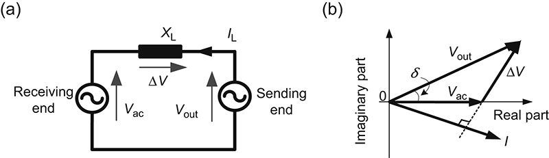
VSCs create an AC voltage waveform on their output in order to exchange active and reactive power with another AC system. Fig. 14.6 shows the schematic diagram and phasor diagram of two AC voltage sources connected through a reactor. The AC voltage, Vout, at the sending end is generated by a VSC and the voltage, Vac, at the receiving end is the voltage of the AC system.
Assuming that there are no power losses in the reactor, XL, shown in Fig. 14.6(a), and that the AC system connected to the AC filter is ideal, then the active power, P, the reactive power, Q, and apparent power, S, transferred through the VSC are:
![]() [14.5]
[14.5]
![]() [14.6]
[14.6]
![]() [14.7]
[14.7]
where δ is the phase angle between the voltage phasor Vout and Vac (in Fig. 14.6(b)) at the fundamental frequency, and is it usually called power angle.
14.4.3. VSC topologies
VSCs can use two-level, three-level and multilevel topologies. These VSC topologies are described in this subsection.
14.4.3.1. Two-level
Two-level VSCs use IGBTs valves to switch between the positive polarity and negative polarity of a charged DC capacitor [20,24]. Fig. 14.7 shows the circuit for one phase of a two-level VSC with the DC capacitor grounded at the midpoint. The two-level VSC is capable of generating an output voltage with two levels ½ Vdc and −½ Vdc between the midpoint of the DC capacitor and the point ‘a’ shown in Fig. 14.7.
Two-level VSCs use a pulse width modulation technique to control the magnitude and phase angle of their output AC voltage. They operate at a high switching frequency of 1 kHz and above, produce high-frequency harmonic components, have high switching losses and require AC filters at their output. Two-level VSCs use a special converter transformer with the capability to withstand high-voltage stresses due to the large DC voltage steps at the converter output. The total power losses of a two-level converter are about 1.6% at its rated transmission capacity [25].
14.4.3.2. Three-level
The four different designs of three-level voltage source converters are neutral point clamped, T-type, active neutral point clamped and hybrid neutral point clamped [26]. Fig. 14.8 shows the circuit of one phase of a neutral point clamped converter. Three-level VSCs have the capability to generate an output voltage with three different voltage levels (½ Vdc, 0 and −½ Vdc) per phase between the point ‘a’ and a neutral point ‘0’ as shown in Fig. 14.8.
The switching signals of their IGBT valves are generated using the PWM technique. They operate at a reduced switching frequency, have lower switching losses, and their transformers are exposed to lesser voltage stresses than the two-level converters.
14.4.3.3. Multilevel
Multilevel converter designs are a more recent development with lower switching frequency, reduced power losses and reduced harmonic components than the two-level and three-level topologies of VSCs. The two types of multilevel converters available on commercial terms are the modular multilevel converter (MMC) [27,28], and the cascaded two level (CTL) [29–31].


Fig. 14.9 shows the schematic diagram of a MMC. Each multivalve arm of the MMC consists of multiple submodules connected in series with an arm reactor. A submodule is formed by a DC capacitor, IGBTs and diodes. Each submodule is capable of producing a voltage step at its output. The submodules in each phase arm (shown in Fig. 14.9(b)–(d)) are switched in the correct sequence to synthesize a sinusoidal AC voltage at the converter output.
The IGBTs of the submodules are turned on once every cycle during steady-state operation. The transformers of MMCs are not exposed to DC voltage stresses and can utilize a simple two-winding transformer (with star/delta connection) [20]. The arm reactors of the MMCs smooth the phase currents and limit the inrush current during capacitor voltage balancing and circulating currents between the phase arms during unbalanced operation [23].
14.4.3.4. Submodule circuits
The three main types of switching circuits in the submodules of the MMCs are half-bridge, full-bridge and clamp double. The half-bridge circuit is the simplest design. It consists of two IGBTs with antiparallel diodes and a DC capacitor as shown in Fig. 14.9(b). The output voltage of the half-bridge circuit is either 0 or the DC capacitor voltage (Vc) [32] and current flows through only one IGBT during steady-state operation. The half-bridge circuit has the lowest cost and the least conduction losses [17,20].

Figure 14.9 Schematic diagram of an MMC-HVDC Scheme (a) Three-phase Topology (b) Half-bridge submodule (c) Full-bridge submodule (d) Clamp double submodule.
The full-bridge circuit has four IGBTs with antiparallel diodes and a DC capacitor as shown in Fig. 14.9(c) [20,32,33]. The voltage output of the full-bridge circuit is +Vc, 0 or −Vc and the current flows through two devices during steady-state operation. It has higher capital costs and increased conduction losses than the half-bridge circuit [34].
The clamp double circuit consists of two half-bridge designs connected in series. The positive terminal of one half-bridge is connected to the negative terminal of the other as shown in Fig. 14.9(d) [23,32,34]. It has five IGBTs with antiparallel diodes, two DC capacitors and two additional diodes. The voltage output of the clamp double circuit is 0, Vc or 2Vc and the current flows through three IGBTs during steady state operation [32–34]. The switch S5 is always in the ON state during normal operation and contributes only to conduction losses. The clamp double circuit has improved efficiency compared to the full-bridge circuit and has higher conduction losses than the half-bridge circuit [33,34].
14.4.3.5. Examples of VSC-HVDC projects
Table 14.1 outlines some examples of existing VSC-HVDC transmission schemes with their converter topologies, ratings, application and commissioning year.
Table 14.1
Examples of existing VSC-HVDC schemes
| Project name (country) | Converter topology | Ratings per converter | Application | Year | |
| Capacity (MW) | Voltage (kV) | ||||
| Estlink (Estonia–Finland) | Two-level | 350 | ±150 | Electricity interconnection and grid reinforcement | 2006 |
| Borwin 1 (Germany) | Two-level | 400 | ±150 | Connection of offshore wind farms | 2009 |
| Cross Sound (USA) | Three-level | 330 | ±150 | Electricity interconnection and grid reinforcement | 2002 |
| Murray Link (Australia) | Three-level | 220 | ±150 | Electricity interconnection and grid reinforcement | 2002 |
| Trans Bay (USA) | Modular multilevel | 400 | ±200 | Electricity interconnection and grid reinforcement | 2010 |
| Borwin 2 (Germany) | Modular multilevel | 800 | ±300 | Connection of offshore wind farms | 2013 |
| Dolwin 1 (Germany) | Cascaded two-level | 800 | ±320 | Connection of offshore wind farms | 2015 |

Information taken from C.-C. Liu, L. He, S. Finney, G.P. Adam, J.-B. Curis, O. Despouys, T. Prevost, C. Moreira, Y. Phulpin, B. Silva, Preliminary Analysis of HVDC Networks for Off-shore Wind Farms and Their Coordinated Protection (Online). Available: http://www.twenties-project.eu/node/18, 2011 (accessed 19.04.15); G. Justin, Siemens Debuts HVDC PLUS with San Francisco's Trans Bay Cable, Living Energy (Online). Available: http://www.energy.siemens.com/hq/pool/hq/energy-topics/publications/living-energy/pdf/issue-05/Living-Energy-5-HVDC-San-Francisco-Trans-Bay-Cable.pdf, 2011 (accessed 18.11.14); D. Das, J. Pan, S. Bala, HVDC light for large offshore wind farm integration, in: 2012 IEEE Power Electronics and Machines in Wind Applications (PEMWA), 2012, pp. 1–7; ABB, DolWin1 (Online). Available: http://new.abb.com/systems/hvdc/references/dolwin1, 2013 (accessed 18.08.14).
14.5. Development of future submarine power transmission schemes
This section describes the development of offshore wind power transmission schemes. The key technologies for future submarine power transmission systems are low-frequency AC transmission, diode rectifiers with VSC inverters, multiterminal VSC-HVDC schemes and the Supernode concept.
14.5.1. Low-frequency AC transmission
Low-frequency AC transmission is a concept that decreases the frequency of AC systems, reduces the cable charging current and extends the distance at which HVAC systems can be cost-effective [26,33]. This could increase the power transfer capacity of a given cable and reduce the number of subsea export cables. At the onshore station, frequency converters would be required to transform the low-frequency AC supply back to the frequency of the onshore grid [26]. There is a need to further research, develop and demonstrate this concept for submarine power transmission systems.
14.5.2. Diode rectifier and VSC inverter
Fig. 14.10 shows an HVDC transmission scheme with a diode rectifier and a VSC inverter for grid connection of offshore wind farms [36–38]. The offshore diode-rectifier platform will have reduced costs, reduced power losses and occupy less space than existing offshore VSC platforms [38].
During start-up operation, an MVAC cable can be used to connect the offshore wind farm to an onshore AC grid, in order to create an AC voltage at the offshore grid. The cable will be disconnected during normal operation and is usually called an umbilical cable.
Multiple diode cells are connected in series to increase the voltage withstanding capability of a converter. The diode valves are arranged into a bridge to form an uncontrolled rectifier. The HVDC transmission scheme shown in Fig. 14.10 consists of an offshore 12-pulse diode-rectifier and an onshore VSC station. It is expected that this new offshore converter design will be available on commercial terms by 2016 [38].

14.5.3. Multiterminal VSC-HVDC schemes
Multiterminal VSC-HVDC schemes are intended to facilitate the transfer of electricity generated from offshore wind farms to land, supply electricity to offshore oil and gas installations and interconnect the grids of adjacent countries. The polarity of a VSC does not change when the direction of power flow changes, hence, multiple VSCs can be connected to a DC bus with fixed polarity to form a multiterminal HVDC (MTDC) system [39–41].
The operation of MTDC grids requires at least one converter terminal to regulate the DC voltage [41]. Onshore converters will connect AC grids and other energy storage plants to DC grids. The onshore converter control will use a DC voltage active power droop control system to maintain the DC voltage and share equal power flow to the converters connected to the DC grid [39]. Offshore converter stations create an AC voltage with a fixed magnitude, frequency, and phase angle at the offshore grid, in order to absorb the active power generated by the wind turbines.
However, the reliable operation of MTDC schemes will require high-power DC circuit breakers and direct current flow control devices, which are still being developed. Manufacturers of DC circuit breakers have announced the results of prototype tests in which direct current exceeding 3 kA was interrupted in less than 3 ms [42,43]. The next step is to deploy such DC breakers into real HVDC networks.
14.5.4. Supernode concept
The Supernode is a concept that is intended to eliminate the requirement for DC circuit breakers in multiterminal HVDC transmission. Fig. 14.11 shows a Supernode for offshore wind power transmission. It consists of an islanded AC network with multiple AC/DC converters. The converters of the Supernode would be required to have fault ride through capabilities and regulate the frequency and AC voltage of the AC island [16]. Additional offshore converter platforms would be required to connect new HVDC circuits to the Supernode and this could result in high grid expansion costs and increased power losses.

14.6. Conclusions
The installed capacity of offshore wind farms in Europe is expected to increase from 8 GW in 2014 to about 23.5 GW in 2020. This chapter described the key technologies required for wind power collection and grid connection of offshore wind farms to onshore grids. Offshore wind farms will use both HVAC and VSC-HVDC submarine power transmission technologies to transfer the electricity generated from offshore wind farms to onshore grids. There is a need to further develop low-frequency AC transmission systems, DC circuit breakers for DC grids and the scheme comprising diode rectifiers and VSC inverters for grid connection of offshore wind farms.
..................Content has been hidden....................
You can't read the all page of ebook, please click here login for view all page.