17

Assembly, transportation, installation and commissioning of offshore wind farms

M. Asgarpour     Energy Research Centre of the Netherlands (ECN), Petten, The Netherlands     Aalborg University, Aalborg, Denmark

Abstract

In this chapter, installation of offshore wind farms is discussed briefly. The installation of offshore wind farms is discussed in four categories corresponding to four main wind farm elements, which are foundations, turbines, substations and cables. For the installation of each category, specialised equipment, vessels and installation methods are necessary. Furthermore, preinstallation activities, such as onshore assembly and offshore transportation, and post-installation activities, such as tests and commissioning are discussed. Precommissioning tests are mandatory to demonstrate proper functionality of turbines and the wind farm as a whole. If all tests are successful, the wind farm can be commissioned and be connected to a grid. In the last section of this chapter, a conclusion is given and innovative offshore installation solutions are described.

Keywords

Array cable installation; Export cable installation; Foundation installation; Offshore transportation; Offshore wind farm commissioning; Onshore assembly; Substation installation; Wind turbine installation

17.1. Introduction

Installation of offshore wind farms is the last step before commissioning of an offshore wind farm, which contributes to approximately 20–30% of development costs or 15–20% of the price of energy. It is projected that the trend of offshore wind installation will grow rapidly in coming years. In Europe alone, by the end of 2014, about 2500 offshore wind turbines were installed, making a cumulative total capacity of 8 GW in 74 offshore wind farms (Corbetta and Mbistrova, 2015). Moreover, there are governmental plans to install another 32 GW of offshore wind energy in Europe by 2020 (European Commission, 2013). This means that the required effort for future distant and large offshore wind farms will be enormous in coming years.
During the development of an offshore wind farm the installation step is typically overlooked, resulting in project delays and noticeable risks and financial consequences. Therefore, it is essential to have a better look into the installation steps and optimise them when possible to reduce the installation costs, risks and delays.
Before the actual offshore installation takes place, the components should be designed and manufactured, be delivered to the onshore assembly site at the harbour, be assembled based on the installation strategy, and then, be transported to the location of the offshore wind farm. The design of the turbine components, such as the tower, the nacelle and blades, is done by the wind turbine manufacturer. In the following sections of this chapter, these steps are briefly described for a typical three-bladed horizontal axis wind turbine.

17.2. Delivery of components

The first step towards installation of offshore wind farms is delivering components to the onshore assembly site at the harbour. These components are:
• Foundation
• Tower sections
• Nacelle
• Rotor
The delivery of onshore and offshore substations is directly to their installation locations and no assembly at the harbour is required. Additionally, array and export cable-laying vessels are already loaded with cables and no harbour assembly is necessary. Foundations of turbines are typically delivered directly to the location of the offshore wind farm and, therefore, no harbour delivery is required.
Typically, a civil engineering office designs the foundation of the turbines and another civil and electrical engineering office designs the onshore and offshore substations. In order to achieve the optimal reliability and minimise the costs, the foundation and the turbine structure should be designed using the same structural tool to make sure all aerodynamic loads are considered in the foundation design and the natural frequency of the complete structure is calculated correctly. Unfortunately, this is not always the case, and turbine manufacturers and foundation designers have strict confidentiality agreements.
When all components are designed and manufactured, they should be transferred to the onshore assembly site at the harbour (Fig. 17.1). Depending of the location of the manufacturer and the component size, the components can be transported on land using oversized trucks or, through the sea, using offshore vessels. It should be noted that there is no need for delivery of all wind farm components at the same time. In fact, there is limited space available at the onshore assembly site and, based on the planned installation strategy, components should be delivered when the previous pack of components is loaded on the installation vessel. Furthermore, typically components providers manufacture the components just before the scheduled delivery date to avoid storage problems.

17.3. Onshore assembly

The onshore assembly site at the harbour is where, based on the installation strategy, all component assemblies are completed and, then, components are loaded onto the installation vessel to be transported to the location of the offshore wind farm (Fig. 17.2).
image
Figure 17.1 Onshore transport of components using oversized trucks on the left or railways on the right.
image
Figure 17.2 Example of onshore assembly site for offshore wind farms at the harbour.
As explained before, there is no assembly required for onshore and offshore substations and typically they are transported to their installation locations. Additionally, there is no assembly necessary for foundations and, depending on their manufacturing location, they can be directly transferred to the location of the offshore wind farm. Therefore, assembly at the harbour only applies to wind turbine components. Based on the installation strategy, the following assembly concepts for wind turbine components are possible:
1. No onshore assembly: all components should be transported to the location of the offshore wind farm and then be installed one by one.
2. Tower assembly: the tower sections (typically three or four sections) are assembled at the onshore assembly site. Then, the whole tower structure is bolted on the deck of the installation vessel to maximise the vessel's loading capacity.
3. Assembly of two blades and the nacelle: the nacelle, hub and two blades are connected together. This concept is also known as the “bunny ear” concept. When the assembly is done, the nacelle with two blades attached is placed on the deck of the installation vessel.
4. Assembly of three blades and the nacelle: this concept is similar to the bunny ear concept, but with the whole rotor attached to the nacelle. The problem of this concept is that the required deck area for each rotor–nacelle assembly is huge and assuming existing offshore vessel designs, only one rotor–nacelle assembly can be loaded on the deck. A workaround is to place the rotor–nacelle assemblies on top of each other, which requires the correct structure on the deck for load handling and damage prevention.
The first concept has been used in installation of several offshore wind farms in the past and has proved to be inefficient for large (more than 15 wind turbines) and far offshore (more than 15 km distance to the shore) wind farms with unsuitable weather conditions. The second concept has proved to be a very efficient choice and nowadays most offshore wind farms are installed using preassembled towers. Based on the deck configuration of the installation vessel, the third concept can be an efficient choice. As stated, the last concept requires specific installation vessels for multiple rotor–nacelle assembly loading and is not an optimal option.
As an optimal assembly concept, depending of the wind farm location and availability of installation vessels, one of the following two concepts can be chosen:
• Tower assembly only
• Tower assembly and the bunny ear rotor–nacelle concept
However, the most optimal installation and assembly concept should be chosen based on the project size, wind farm location and availability of installation vessels.

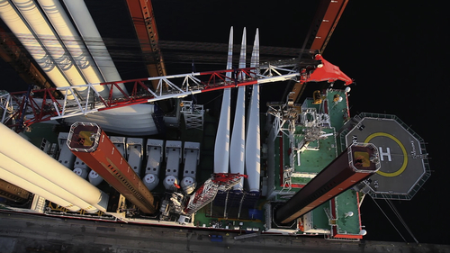
17.4. Offshore transport

The last step before the installation of an offshore wind farm is transportation of all components to the location of the offshore wind farm. As stated before, depending on the location of the harbour, wind farm and manufacturing facilities, the foundations and offshore substations can be directly transported to the location of the farm. However, wind turbine components are typically transported to the onshore assembly site at the harbour and then are loaded on installation vessels.
Currently, there are several installation vessels customised for offshore wind industry and more optimised vessels are in the design phase. Depending on the project specification, one of the following installation vessels can be selected for foundation, substation and turbine installation:
• Floating vessel stabilised with mooring lines
• Floating vessel equipped with motion-compensated crane
• Jack-up barge
Currently, jack-up barges (Fig. 17.3) are used most often for close to shore wind farm locations and floating vessels with motion-compensated cranes are used for deep waters. For array and export cable installation, custom-made vessels are used. These vessels are customised for cable laying, trenching and rock dumping.
For each specific project and installation strategy an installation vessel is reconfigured for equipment placement and deck preparation. This step is normally called the mobilisation and takes place before loading the components from the manufacturing facilities or the onshore assembly site at the harbour to the deck of the vessel. When the installation is finished, the deck area is reconfigured for the next offshore wind installation. This step is normally called demobilisation. Mobilisation and demobilisation of large installation vessels are costly and time-consuming (each operation can take up to one month).
After the mobilisation of the installation vessel and loading the components to the deck of the vessel, the vessel can sail to the location of the wind farm. It should be noted that sailing out to the location of the wind farm can only take place when the weather conditions at the location of the wind farm are suitable for the next installation step. Otherwise, the vessel will wait at the harbour for suitable weather conditions, but the vessel daily rate should still be paid. This delay is normally known as weather delay and for far offshore wind farms can be a significant project risk. Therefore, it is advisable that, based on the historical weather data, the weather delay per installation step be calculated. If this calculation is done, the optimal starting date for the installation can be found to minimise the total weather delay.
image
Figure 17.3 A jack-up barge during loading before sailing out to the location of the offshore wind farm.

17.5. Offshore installation

The installation step of offshore wind farms is when the years of planning come to reality. This step starts when the installation vessel with foundations arrives at the location of the wind farm to install the first foundation, and finishes when the cable installation vessels connect the offshore substation to the onshore substation through export cables. Installation of offshore wind farms can be categorised in four steps:
• Foundation installation
• Turbine installation
Tower
Nacelle
Rotor
• Substation installation
Offshore substation
Onshore substation
• Cable installation
Array cables
Export cables
In the following sections these steps are briefly described.

17.5.1. Foundation installation

Depending on the foundation type, the installation vessel and strategy may differ. Currently, approximately 90% of offshore wind turbines are installed on monopiles and the remainder are installed on jackets, tripods or gravity-based support structures. There are also a few demonstration floating turbines, which have no bottom-fixed foundations.

17.5.1.1. Monopiles

Monopiles are large hollow steel or concrete tubes, whose thickness and diameter vary based on the turbine size, soil condition and water depth. Before installation of a monopile, a layer of scour protection should be applied to avoid seabed erosion around the monopile. This first scour protection layer is made by rock dumping around the monopile position. When the first layer of scour protection is made, monopiles are lifted from the installation vessel and then positioned on the seabed.
Common installation methods of monopiles are pile driving using a hydraulic hammer or pile drilling (Fig. 17.4). On average it takes about one or two days to install a monopile using these methods. If pile driving using a hydraulic hammer is chosen, depending on the seabed condition and water depth, it takes about 2000–3000 hammer hits to drive the monopile into the ground. During the pile driving or drilling, the piling depth is continuously monitored to make sure the monopile is placed into the correct depth. Since for hammering or drilling a stable platform is required, normally jack-up barges are used for monopile installation.
If a monopile is used as a foundation, in order to connect and level the turbine tower to the monopile, an extra component, called the transition piece, is necessary.
image
Figure 17.4 Pile driving by a hydraulic hammer equipped on a jack-up barge.
The transition piece is lifted and placed on the top of the monopile and then the space between the monopile and the transition piece (about 10–20 cm thick) is grouted. The top of the transition piece is used as the work platform and the sides are used for boat landing and ladder placement. Moreover, J-shaped tubes are placed on the side of the transition piece to guide the array cables from the tower to the seabed.

17.5.1.2. Jackets and tripods

The installations of jackets and tripods to some levels are similar to each other. Similar to the monopile installation, a first layer of scour protection by rock dumping is required (Fig. 17.5). The jackets or tripods are transported to the location of the wind farm using jack-up barges or floating vessels with mooring line stabilisation. When the installation vessel is positioned, the jacket or tripod is lifted and placed on the seabed. Alternatively, the jacket or tripod can be floated and then, using a crane, be positioned. In that case, a heavy lift crane is no longer required. When the structure is positioned into the location, for jackets, four piles and for tripods, three piles are driven into the seabed to fix the foundation. The pile-driving methods for jackets and tripods are similar to monopiles. When the foundation installation is finished, the turbine tower can be installed directly on the topside of the jacket or the tripod.

17.5.1.3. Gravity-based foundation

Gravity-based foundations are normally self-buoyant and can be floated or towed out to the location of the offshore wind farm. Since the placement of the gravity-based foundation on the seabed requires a flat area, seabed preparation and scour protection steps are needed. When the seabed is prepared and the foundation is positioned in the right location, the foundation is sunk by influx of water, and then the base of the foundation is filled with ballast to anchor the foundation. When ballasting is finished, the turbine tower can be directly installed on the topside of the gravity-based foundation.
image
Figure 17.5 Scour protection after installation of the monopile (shown in gray) and the transition piece (shown in yellow).

17.5.2. Turbine installation

The turbine components to be installed are the tower, nacelle, hub and blades. The first installation step starts with the tower. As discussed before, the tower sections are typically assembled at the onshore assembly site at the harbour and the complete tower is transported to the location of the wind farm by a jack-up barge (Fig. 17.6). When the installation vessel is in position and stabilised, the tower is lifted and placed on top of the foundation and then bolted. If tower sections are not assembled at the onshore assembly site, the assembly takes place offshore, which logistically takes more time and effort due to the harsh weather conditions offshore.
The second turbine component to be installed is the nacelle. Similar to the tower, the nacelle is lifted by the crane off the installation vessel and placed on the top of the tower. If the blades are not already attached to the nacelle, each blade should be lifted separately and connected to the hub. Then, in order to not change the position of vessel or crane, the rotor is rotated to make space for installation of a new blade. This operation is iterated up to the moment that all three blades are installed.

17.5.3. Substation installation

In order to connect the wind turbine generators to a grid, proper electrical infrastructure is required. If an offshore wind farm is located near to shore, an onshore substation is sufficient; but if the wind farm is located distant from the shore, both onshore and offshore substations are required. In this section, only the installation of offshore substations is discussed (Fig. 17.7), since onshore substation installation follows typical onshore civil works.
image
Figure 17.6 Offshore wind turbine blade installation using a jack-up barge.
Prior to the installation of an offshore substation, its foundation should be installed. Typical choices for the foundation of an offshore substation are jackets or gravity-based foundations. When the foundation is installed, the complete substation should be lifted from the installation vessel and be placed on top of the foundation.

17.5.4. Cable installation

The last step of offshore wind farm installation is cable installation. Depending on the size and location of the wind farm, array cables connecting the output power of turbines are connected to one or two offshore substation busbars. Then, using export cables, the high-voltage electricity produced by the offshore wind farm is transferred to the onshore substation and from there, to the local electrical grid. The array and export cable routes are planned in such a way as to minimise the total cable length and follow all environmental laws and marine restrictions. In the following, the installations of array and export cables are discussed separately.

17.5.4.1. Array cable installation

The array or infield cables are lines of cables connecting several turbines to an offshore substation. If a monopile foundation is used, the array cables are pulled through J-tubes and then are connected to the wind turbine cables in the tower bottom. After cable pulling, a second layer of scour protection by rock dumping should be applied around the foundation.
image
Figure 17.7 Offshore wind substation installation.
image
Figure 17.8 Cable burial into the seabed using a remotely operated cable trencher.
The array cables should be placed 1 or 2 m under the seabed in the space between wind turbines. This is done using trenching remotely operated vehicles (ROV) departed from an offshore vessel and monitored by an experienced pilot so as to not damage the cables (Fig. 17.8). The trenching ROV buries the array cables 1 or 2 m below the seabed, depending on the environmental requirements and IEC and DNV standards (eg, DNV-RP-J301 guideline). The last turbine in a row is connected to an offshore substation. This operation should be done for each row of connected turbines.

17.5.4.2. Export cable installation

After connecting array cables to offshore substations using transformers, the voltage is stepped up for onwards transmission over a longer distance. The export high-voltage AC or DC cables connect the offshore substations to an onshore substation. The installation of export cables is similar to array cables, but larger cable-laying vessels and trenching ROVs are used. Typically, the cables near shore should be buried deeper than those far from the shore. After export cable installation, precommissioning tests can be carried out and then, the offshore wind farm can be commissioned.

17.6. Tests and commissioning

Before and after commissioning of an offshore wind farm several tests are carried out to make sure that the wind farm components have proper functionality and the wind farm can be connected to an electrical grid as a stable power plant. As a generic guideline, DNV-OSS-901 can be used for project certification of offshore wind farms. Depending on the project location and regulations of the wind farm operator, the wind turbine manufacturer and the grid operator, several tests may be mandatory for commissioning of an offshore wind farm. According to NoordzeeWind (2008) and Larsen et al. (2009), the following tests should be carried out on wind turbines, Supervisory Control And Data Acquisition (SCADA) system, foundations and electrical system of offshore wind farms:
• Factory acceptance tests
• Site acceptance tests
• Commissioning tests
• Completion test
• Performance tests

17.6.1. Factory acceptance tests

Factory acceptance tests are several dimensional, material and functionality tests that should be performed during and after manufacturing of foundations and wind turbine components. During factory acceptance tests all component certifications should be reviewed and approved. After the factory acceptance tests, components can be delivered to the onshore assembly site or their installation location.

17.6.2. Site acceptance tests

Site acceptance tests are typically done on the SCADA system to ensure proper communication between wind turbines and the electrical infrastructure of the wind farm. In addition to the communication tests based on IEC 104, aviation lights, uninterruptible power supply (UPS) and automation modules should also be tested.

17.6.3. Commissioning tests

Commissioning tests are performed on wind turbines, foundations and electrical system components to demonstrate their safe and proper operation.
Typical commissioning tests of wind turbines are:
• Test of wind turbine generator while connected to the grid (a few hours)
• Test of wind turbine generator while grid loss occurs
• Wind turbine vibration test
• Test of yaw system
• Test of pitch systems
Typical commissioning tests of the electrical infrastructure and foundations are:
• Test of power measurement system
• Test of array and export cable voltages
• Test of transformer cooling equipment
• Test of control equipment
• Test of the diesel generator, if available
• Conductivity tests of the concrete reinforcement
• Test of proper grounding of cable connections

17.6.4. Completion tests

Completion tests can be performed when all commissioning tests are carried out successfully. Completion tests are done for wind turbines individually and for the wind farm as a whole to demonstrate their promised functionality.
Completion tests of each individual wind turbine are typically planned as a continuous operation of the grid-connected turbine for several days where the turbine faults do not exceed a maximum number. The completion test of the wind farm is also typically planned as a continuous operation of all wind turbines, while all of them are producing power and total availability is above a minimum number. The terms and thresholds of completion tests are normally set by wind farm operator and wind turbine manufacturer.

17.6.5. Performance tests

During the warranty period of the wind farm (typically a 5-year warranty), the wind farm operator has the right to perform several performance tests and check whether the wind farm is functioning and producing power as stated in contract terms. According to Larsen et al. (2009) performance tests on wind turbines are:
• Availability test: time availability of wind turbines, which is defined as the relationship between the time that the wind turbine has been available to produce power to the gird and the time where the grid has been available to receive the produced power from the wind turbine.
• Power cure test: the measured power curve of wind turbines is validated against their reported power curve by the wind turbine manufacturer. The power curve measurement should be based on IEC 61400-12 standard and other regulations set by local authorities.
• Electrical system test: in this test the power losses occurring in the main transformer, high- and medium-voltage cables are measured and their compliance according to defined thresholds is demonstrated.
• Acoustic noise test: the emitted noise of the wind turbines according to IEC 61400-11 is measured and compared to defined environmental thresholds.
If the wind farm passes all commissioning and completion tests, then it can be officially commissioned. It should be noted that for large wind farms, sometimes half of the wind farm is commissioned earlier and the official commissioning takes place when all the turbines and electrical infrastructure are ready for commissioning.

17.7. Conclusions and future trends

The installation of offshore wind farms can only be done successfully if several consecutive and parallel steps are executed according to the project plan and defined budget. Due to the harsh offshore environmental conditions, the installation of offshore wind farms is associated with high risks and costs. It is estimated that future offshore wind farms will be located even further offshore and consequently in deeper waters and with harsher weather conditions.

17.7.1. Optimal installation planning

There is no generally optimal installation strategy for all offshore wind farms. Depending on the wind farm size, the wind farm distance to the shore, water depth and climate conditions, an optimal installation strategy can be defined to minimise the installation costs and risks.
During recent decades, inadequate attention has been paid to installation planning and optimisation of offshore wind farms and only a limited number of planning and optimisation tools, such as OWECOP (Herman, 2002) and ECN Install (Asgarpour et al., 2014) are available in the market for public use. As an example, using the ECN Install tool, the whole process of foundation, turbine and cable installation can be modelled and available resources can be allocated to each installation step (Fig. 17.9). With the chosen installation strategy, the planning of the whole process can be derived and costs and resources associated with each installation step can be calculated. Furthermore, based on the defined installation strategy, total operation time, weather delays and costs are calculated and the commissioning date is estimated.
A generic installation planning tool can be used by all parties involved in the installation of offshore wind farms and facilitate their collaboration. By using such a tool, the owner of the wind farm can monitor the work carried out by different parties and ensure a smooth project execution according to the budget and planned schedule. The insurance and financial institutes can identify risks associated with each individual installation step and update their policies accordingly. The vessel and equipment owners can have an estimation of all possible delays within the project and reschedule their future projects consequently. Moreover, engineering offices can use the installation planning tool to demonstrate the added value of their innovative solutions compared to traditional installation strategies. In the following, two innovative installation solutions are described briefly.
image
Figure 17.9 ECN Install tool for optimal planning of offshore wind installation projects.

17.7.2. Offshore harbour

Offshore installation vessels are the main contributor to high installation costs of offshore wind farms. One way to reduce the installation time and costs is to reduce the operation hours of expensive jack-up barges. In order to reduce the operation hours of the jack-up barges, an offshore harbour can be used (Fig. 17.10). The offshore harbour can be designed as a floating pontoon structure moored to the seabed. If an offshore harbour is available, a cheaper feeder can feed new components to the offshore harbour continuously. Then, the expensive jack-up barge does not need to travel back and forth to the onshore assembly site to load new components.
In Asgarpour et al. (2015) it is shown that for a 300 MW offshore wind farm with 85 km distance to the shore, an offshore harbour can significantly reduce the installation time and costs.

17.7.3. Breakwaters

Vessels and equipment used for offshore wind installation can only operate when the significant wave height is below a certain limit, typically when it is less than 1.5 m. Due to the harsh weather conditions offshore and vessel operational restrictions, significant weather delays, which are associated with high costs, occur during the project. Therefore, it is beneficial to make use of breakwaters around the installation location to attenuate waves to an acceptable level. Moreover, if breakwaters are placed in the surroundings of the wind farm, less expensive installation vessels with lower significant wave height restrictions can be used. In Asgarpour et al. (2015) it is shown that by using one or two rows of breakwaters moored to the seabed around the location of the installation vessel, the wave height and consequently, the weather delays, can be reduced significantly.
image
Figure 17.10 Example of a pontoon structure loaded at the harbour to be used as a floating offshore harbour.
As discussed, offshore wind share in the produced electricity market is growing rapidly, but installation of offshore wind farms is still not mature enough. Therefore, new innovative installation solutions are required to reduce the costs and risks of future large and far-offshore wind farms and to make offshore wind farms competitive with conventional power plants.

References

Asgarpour M, Dewan A, Savenije L.B. Commercial proof of innovative installation concepts using ECN install. In: European Wind Energy Association (EWEA). Copenhagen: EWEA; 2015.

Asgarpour M, Dewan A, Savenije L.B. Robust installation planning of offshore wind farms. In: International Wind Engineering Conference (IWEC). Hannover: Fraunhofer; 2014.

Corbetta G, Mbistrova A. The European Offshore Wind Industry – Key Trends and Statistics 2014. 2015 Brussels.

European Commission. Report from the Commission to the European Parliament, the Council, the European Economic and Social Committee and the Committee of the Regions – Renewable Energy Progress Report. 2013 Brussels.

Herman S.A. Offshore Wind Farms – Analysis of Transport and Installation Costs. 2002 Petten.

Larsen P.E, Larsson Å, Jeppsson J. Testing and Commissioning of Lillgrund Wind Farm. 2009 Sweden.

NoordzeeWind. Off Shore Windfarm Egmond Aan Zee General Report. 2008 The Netherlands.

..................Content has been hidden....................

You can't read the all page of ebook, please click here login for view all page.
Reset
3.135.200.14