
Previous Chapter
17. Assembly, transportation, installation and commissioning of offshore wind farms
18
Condition monitoring of offshore wind turbines
Abstract
In this chapter, vulnerable offshore wind turbine components, which could lead to long downtimes, are discussed based on the reliability data observed. As the failures of these components can potentially lead to long downtimes and significant revenue loss in the offshore environment, their operation and health condition should be properly monitored. In this chapter, the significance of monitoring these vulnerable components is further emphasized through discussing the consequent economic impacts of their failures. Following this, the relevant wind turbine condition monitoring techniques and commercially available wind turbine condition monitoring systems are discussed. Finally, the chapter ends with a summary of the existing challenges and issues as well as the future research tendencies in the field of offshore wind turbine condition monitoring.
Keywords
Condition monitoring; Offshore; Reliability; Wind turbine18.1. Reliability of offshore wind turbines
Up to now, various wind turbine (WT) concepts have been developed. However, the technology of modern wind power has not yet been fully matured and standardized. Based on the configuration of the drive-train subassemblies, these WTs can roughly be classified as [1]:
• Geared WTs, with a gearbox, a high-speed asynchronous generator, and a partially rated converter;
• Geared WTs, with a gearbox, a medium-speed synchronous generator, and a fully rated converter;
• Direct-drive WTs, with no gearbox but a low-speed synchronous generator and a fully rated converter.
Recently, a few innovative concepts of WTs have also been developed, such as the semidirect-drive WT developed by Goldwind [2]; the WT adopting digital displacement transmission [3], etc. In principle, these innovative designs are superior to conventional concepts in system reliability and efficiency. However, they are still currently in research. Further verification of their actual performance under various operation conditions is still required. Therefore, nowadays the mainstream products in the commercial wind power market are geared and conventional direct-drive WTs. To understand the basic reliability and failure modes of both types of WTs, a survey of different concepts of onshore WTs was conducted by the UpWind project [4], and the results are shown in Fig. 18.1.
Fig. 18.1 shows that direct-drive WTs are superior to the conventional gear-driven WTs in the following aspects:
• free of gearbox failure;
• improved reliability for the hydraulic system;
• less problems in mechanical brakes.
However, as concluded in Ref. [6], direct-drive WTs suffer from more problems in electric subassemblies (eg pitch control and power electronic converter), rotor blades, and generators. Similar conclusion also drawn in the survey of the reliability of Enercon E32/33 direct-drive WTs, see Fig. 18.2, where the failure rate and downtime data were taken from Scientific Measurement and Evaluation Programme (WMEP) [7] managed by Fraunhofer IWES under the German publicly funded programme ‘250 MW Wind’ during a 17-year period. The WMEP programme collected 193,000 monthly operation reports and 64,000 maintenance reports from 1500 WTs, which cover approximately 15,000 turbine years. These data are considered to be the most thorough collection of publicly available onshore WT reliability information to date [8].

Figure 18.1 Reliability of geared and direct-drive wind turbines. Reproduced from W. Yang, Condition monitoring the drive train of a direct drive permanent magnet wind turbine using generator electrical signals, J. Sol. Energy Eng. 136 (2014) 021008.

Figure 18.2 Reliability characteristics of WMEP survey. (a) E32/E33 – 1357 turbine-years (b) WMEP survey – 7800 turbine-years. Reproduced from P. Tavner, D.M. Greenwood, M.W.G. Whittle, R. Gindele, S. Faulstich, B. Hahn, Study of weather and location effects on wind turbine failure rates, Wind Energy 16 (2013) 175–187.
From Fig. 18.2, it is seen that in spite of turbine types, electrical, electronic control, hydraulic and yaw systems have shown much higher failure rates than rotor blades, gearboxes and generators do. However, they lead to shorter downtimes as they are easier to replace and repair. In contrast, rotor blades, gearboxes and generators show relatively low failure rates, but result in much longer downtimes due to the difficulties in logistics, lifting, replacing and repairing.
However, it should be known that the information illustrated in Fig. 18.2 was for onshore WTs. A recent study also discloses that in onshore cases, 75% of the faults cause 5% of the downtime, whereas 25% of the faults cause 95% of the downtime [9]. In other words, downtime onshore is dominated mainly by a few large faults, many of which were associated with gearboxes, generators and blades that are difficult to replace or repair. This 5% of the downtime was mostly associated with the electrical and power electronic control systems, whose defects are relatively easy to fix in an onshore environment. As failure modes of an offshore WT are similar to its onshore counterpart, the failure rates of an offshore WT would be similar to those shown in Fig. 18.2, although the wet and corrosive offshore environment could affect more or less the failure rates of WT components. However, it is well known that downtime offshore is significantly affected by the accessibility of the offshore wind farm. Therefore, it is deemed that the downtime figure of an offshore WT would be quite different from those shown in Fig. 18.2. For example, the failure of a power electronic control system results in short downtime onshore attributed to the potential ease of repair. However, it could lead to a very long downtime offshore, as the downtime offshore is often dictated by unfavourable weather and sea conditions rather than being solely dependent on how quick the fault can be fixed [10].
Condition monitoring (CM) of offshore WTs should extend beyond monitoring only drive-train subassemblies (eg blades, gearbox, and generator), to monitoring non-mechanical subassemblies (eg electrical and power electronic control systems). Early practice has shown that offshore operation and maintenance (O&M) is much more costly and sophisticated than onshore O&M [1]. Particularly in unfavourable seasons, the wind farm may be inaccessible for long periods. As a consequence, any breakdown that needs manual repair or reset could lead to a long downtime and significant revenue loss. However, if the breakdown can be predicted in advance with the aid of a CM system, it will be beneficial to the operator in finance. Even in favourable seasons, visiting an offshore site is still expensive due to the high cost of hiring suitable vessels. Nowadays, the operator still prefers to conduct routine offshore WT maintenance via visual inspection at the site. Frequent site visits could lead to many unnecessary costs that increase the cost of energy of offshore wind. However, the kind of costs resulting from unnecessary site visits can be reduced if the WT is equipped with a remote CM system. Therefore, an effective CM system is essential to an offshore WT in order to achieve high availability and good economic return.
18.2. Challenges in offshore wind turbine operation and maintenance
From the point of view of WT CM, the challenges in the O&M of an offshore WT can be summarized as follows:
1. Offshore WTs show few unexpected failure modes associated with the offshore environment, except those due to the offshore AC connector cable arrays and AC export cables. For this reason, the CM techniques used for onshore WTs are equally applicable to offshore WT CM. However, in offshore circumstances more functions need to be considered to avoid the long downtime associated with offshore logistics.
2. Offshore weather has a significant influence on the O&M of offshore WTs. Early experience has shown that the higher the wind speed, the lower the availability. This is due to both the increased outages and the limited access to defective WTs in windy weather. Such a view is supported by the data presented in Ref. [9], which shows that the availability of offshore WTs can be improved if the maintenance and repair activities can be well scheduled. In addition to the impact of offshore weather, the availability of an offshore WT is also influenced by the availability of suitable vessels, spare parts and maintenance crews.
3. The accessibility of the offshore wind farm is pivotal to keeping the desired availability of offshore WTs. Take one of the UK Round 3 projects, Dogger Bank as an example, its minimum distance to Blyth is 118 km, while the maximum distance is 200.6 km [1]. This means that an oilfield support vessel (with excursion speed 12 knots) from Blyth would take over 10 h sailing time to the nearest edge of Dogger Bank and 17 h to the furthest edge of the site. Obviously, the long sailing time and narrow window of favourable offshore weather bring challenges to the maintenance of offshore WTs.
4. At present, the average cost of a transfer boat is about £73 per hour [1]. The daily rate of jack-up vessels that are used for offshore WT installation and big maintenance varies from £67,800 to £259,900, depending on the vessel types and the contract with the ship owner [11]. However, it should be known that many of these vessels are not able to cover those offshore wind farms located far from shore, eg Dogger Bank, because they can only travel up to 111 km from a safe harbour. Moreover, they are not allowed to travel on sea when the significant wave height is more than 1.5 m, which makes the >98% accessibility an impossible target to achieve. In addition, the carrying and lifting capability of such vessels is often limited. For these reasons, installation vessels with access systems and helicopters are still options when carrying out the maintenance of those WTs deployed far from shore. The extremely high cost so caused is an issue.
5. Offshore WT maintenance is a very young industry field. To date, there has not been a purpose-designed vessel available specifically to fit the needs of this market. Currently, the offshore WT maintenance work is undertaken either by offshore wind farm installation vessels or by oil and gas jack-up vessels. Wind farm construction vessels are often bounded on busy wind farm construction activities, their availability to WT maintenance work is limited and, moreover, they are usually oversized compared to the actual requirement by offshore WT maintenance. Meanwhile, oil and gas jack-up vessels are extremely expensive to use and, moreover, they cannot always meet the purposes of offshore WT maintenance. For example, their crane is small, their legs are too short, poor jacking performance, much downtime due to poor workability, etc. Therefore, a purpose-designed offshore WT maintenance vessel is still wanted today.
6. Compared to vessels, helicopters enable quicker access to far offshore sites. Thus, they seem an ideal tool for carrying out maintenance at distant offshore sites. However, the practice of Horns Rev 1 indicates that helicopters are unable to cover all site access issues. In other words, helicopters do overcomes the issue of distance, however, their safe operation is still limited by poor weather conditions (eg low visibility, strong wind shear and turbulence, etc.). Moreover, it should be noted that the oil and gas industry has reduced the use of helicopters in operations because, historically and statistically, helicopters have been identified as one of the most dangerous aspects of offshore activities [1].
In summary, accessing difficulties, low availability, and high cost characterize the O&M of offshore WTs. However, in principle all these challenges can be mitigated through efficient CM of WTs. Therefore, remote CM is essential for offshore WT from the point of view of O&M.
18.3. Offshore wind turbine condition monitoring techniques
Basically, the CM techniques used for monitoring onshore WTs are seen to be applicable to offshore WT. However, there are still a number of fundamental challenges, as listed below, that need to be addressed specifically when developing offshore WT CM systems (CMSs) [12].
18.3.1. Far offshore distance of newly developed offshore wind farms
Statistics [1] show that the average offshore distance of the UK Round 3 offshore wind farms is 93.7–189.4 km, compared to the offshore distance of the Round 1 and 2 offshore wind farms of 8.6–16 km. Moving wind farms to farther offshore brings more challenges to WT maintenance because the far offshore distance makes the site more difficult to access, particularly in winter. For this reason, the time window suitable for WT maintenance becomes narrower as the maintenance activity cannot be performed under unfavourable sea and weather conditions. As a consequence, components that even have minor problems would have to be repaired or replaced in advance to avoid potential long downtime that could result in their failure during unfavourable seasons. This will inevitably waste much of the remaining life of the WT components thus leading to significant financial loss. For this reason, different from those CMSs installed in onshore WTs, the CMSs designed for offshore WTs will play a vital role in remaining life prediction in addition to conducting the conventional operation and health CM tasks. However, it is well known that accurate remaining life prediction is not easy to achieve in practice, particularly in harsh offshore environments, as the ultimate loads in extreme weather and wet, salty and corrosive sea air will accelerate the development of faults.
18.3.2. Large diversity of the offshore WT concepts
Since 2008, the market share of the gearless or direct-drive turbines has increased from 12% to 20% [13]. This means that there are more and more WTs of different concepts appearing in onshore wind farms. At present, the offshore wind market is still dominated by gear-driven turbines. However, the diversity of offshore WTs will increase sooner or later. Since different concepts of WTs have different working mechanisms and hardware configurations, different CMSs and the associated CM techniques are needed to meet the specific CM purposes. Currently, the commercially available WT CMSs are mostly vibration-analysis-based systems, which are good at detecting gear and bearing faults occurring in gear-driven WTs. However, whether these systems can be equally effective in detecting the fault occurring in other concepts of WTs is questionable. For example, Fig. 18.2 shows that a power electronic system leads to a significant number of failures in a WT. However, these failures cannot be successfully detected by the existing vibration-analysis-based systems. Therefore, how to enhance the CM capability of a WT CMS and enable it to be applicable to monitoring more types of faults and more concepts of WTs is a challenging issue that needs to be solved when developing the future offshore WT CMSs.
18.3.3. Increased offshore WT size
Due to less visual, noise, land usage and social constraints, offshore WTs are, in general, larger than their onshore counterpart to maximise the economic benefit. In theory, the reliability of a WT is independent of its size. However, a survey of more than 6000 onshore WT years for turbines ranging from 300 to1800 kW in Denmark and Germany over 11 years has shown that larger WTs did experience more failures than smaller ones [14]. The immature design technology, variable-speed operation, sophisticated control, and lack of experience of operating large WTs can account for such of the survey conclusions. Therefore, an efficient CMS is demanded by large WTs to mitigate this issue. The added value of a CMS is also highlighted by the incurring significant revenue losses due to the breakdown of large offshore WTs. However, how to detect incipient mechanical and/or electrical faults from large offshore WTs operating at constantly variable speeds is a challenging issue that remains to be solved.
18.3.4. Increased use of electrical and power electronic components
Modern WTs use sophisticated control systems for pitch, generator and converter controls. However, practice shows that electrical and power electronic components are in general less reliable than mechanical components [15,16]. Their failure may not a matter on onshore occasions attributed to the potential ease to repair. However, their failure would lead to a long downtime with significant economic losses farther offshore due to reduced accessibility. Current WT CMSs are not designed for detecting the faults that occur in these electrical and electronic systems. Therefore, how to enhance the CM function of the CMSs and enable them to look after more WT components is an issue worthy to consider when developing offshore WT CMSs. Many preliminary researches have been conducted in recent years [17], the achievements of which will be very helpful in obtaining a final solution.
18.3.5. High cost of offshore WT CM
With the continual boom of the offshore wind industry, more and more offshore WTs will be deployed farther offshore in coming years [18]. In the future, hundreds of WTs would be installed in a wind farm. Assume the unit prices of a vibration-analysis-based CMS is approximately £10,000, then to equip each WT with such a CMS will cost the operator at least £10 m. As a CMS is in essence a power electronic system, it is not reliable in a wet, salty and corrosive offshore environment. Once the WT CMSs breakdown due to component failure, not only is the individual WT left unprotected but a large capital loss will result. For this reason, the future offshore WT CMS must be not only efficient and cost-effective but also reliable enough when operating offshore.
To date, there are a number of non-destructive testing (NDT) techniques that can be used in WT CM. They are either proven in the laboratory or have already been used in practice. A brief review of them can be found from Refs. [19–23] and their features are reviewed in Table 18.1 [12]. In the table, the costs of different NDT techniques are classified as follows:
• Low: <£2000
• Medium: £2000–5000
• High: £5000–10,000
• Very high: >£10,000.
However, it should be known that the costs vary depending on measurement accuracy, resolution, functionality and applicable environment.
From Table 18.1, the features and potential applications of various NDT techniques can be summarized as follows:
• Vibration analysis and oil particle counters, being low-cost and well-proven, are feasible monitoring techniques. Moreover, their combined use could be a key to WT drive-train monitoring. Currently vibration analysis is more widely used for tracing the growth of WT gearbox and bearing faults than oil particle counters.
• Oil quality analysis is valuable for gearbox gear and bearing monitoring, in particular fault diagnosis through analysing the composition and shapes of lubrication oil metal particles. In the meantime, it is also an effective approach to monitoring the aging and contamination of the lubrication oil itself. However, it is most likely to be used offline due to high cost.
• Shaft torque and torsional vibration measurement have been investigated but torque transducer installation will be costly and may be limited by the compact structures of new-generation WTs.
• Ultrasonic testing is a potentially effective tool for detecting the early WT blade or tower defects, although its application requires methods for scanning the individual components.
• Thermocouples are cheap and reliable. They are extensively used for monitoring the nacelle, gearbox and generator bearings, lubrication and hydraulic oil, and power electronic temperatures. By contrast, thermography is rarely used because of the high cost of the thermographic camera and difficulties in practical application in operating WTs, although its potential application in WT CMS has been investigated [21].
• Fibreoptic strain measurements are proving a valuable technique for measuring blade–root bending moments as an input to advanced pitch controllers and can be used to monitor WT blades. They have been demonstrated in operation and improvements in costs and reliability are expected. By contrast, mechanical strain gauges are used only in lab tests as they are prone to failure under impact and fatigue loads.
• Acoustic emissions could be helpful for detecting drive-train, blade or tower defects during type tests but is has wide bandwidth and is costly, both to measure and analyse. Vibroacoustic techniques have had success, for example, in the aerospace industry, but their costs would be prohibitive for the wind industry and the WT nacelle is not ideal for collecting microphone data.
• Shock pulse method (SPM) [22] could be an alternative online approach to detecting WT bearing faults, although further experience is still needed in the wind industry.
Table 18.1
Non-destructive techniques applicable to wind turbine condition monitoring
| No | CM techniques | Cost | Online CM | Fault diagnosis | Deployment | WT components |
| 1 | Thermocouple | Low | Y | N | Already used | Bearings Generator Converter Nacelle Transformer |
| 2 | Oil particle counter | Low | Y | N | Already used | Gearbox Bearing |
| 3 | Vibration analysis | Low | Y | Y | Already used | Main shaft Main bearing Gearbox Generator Nacelle Tower Foundation |
| 4 | Ultrasonic testing | Low to medium | Y | N | Being tested | Tower Blades |
| 5 | Electric effects (eg discharge measurement) | Low | Y | N | Already used | Generator |
| 6 | Vibroacoustic measurement | Medium | Y | N | N | Blade Main bearing Gearbox Generator |
| 7 | Oil quality analysis | Medium to high | N | Y | N | Gearbox Bearing |
| Table Continued | ||||||

| No | CM techniques | Cost | Online CM | Fault diagnosis | Deployment | WT components |
| 8 | Acoustic emission transducers | High | Y | N | N | Blade Main bearing Gearbox Generator Tower |
| 9 | Torsional vibration (encoder-based) | Low | Y | N | Being tested | Main shaft Gearbox |
| 10 | Fibre optic strain gauges | Very high | Y | N | Already used | Blade |
| 11 | Thermography | Very high | Y | N | N | Blade Main shaft Main bearing Gearbox Generator Converter Nacelle Transformer |
| 12 | Shaft torque measurement | Very high | Y | N | Being tested | Blades Main shaft Main bearing |
| 13 | Shock pulse method (SPM) [22] | Low | Y | N | N | Bearing Gearbox |

Reproduced from W. Yang, P. Tavner, C. Crabtree, Y. Feng, Y. Qiu, Wind turbine condition monitoring: technical and commercial challenges, Wind Energy 17 (5) (2014) 673–693.
It is worth noting that the aforementioned CM techniques were designed mainly for monitoring WT drive-train components. However, the high failure rate of power electronic components and their potentially long downtime offshore suggest that it is essential to perform the in situ monitoring of those power electronic components. This will be very helpful in achieving high availability of an offshore WT. In recent years, much effort has been spent in this field. Unfortunately, a fully successful technique dedicated to monitoring WT power electronic systems has not yet been achieved. For example, although investigations have been done to understand the failure modes of power electronic components (eg [16,26–28]) and based on which some interesting CM techniques have been developed, such as temperature measurement [29,30], eddy current pulsed thermography [31], resistance and capacitance measurements [32], etc. However, the majority of these techniques were designed for monitoring individual components rather than the whole power electronic control system. In reality, it is not realistic to install a large number of transducers to monitor all individual components within the constraints of both space and cost. Therefore, to develop an innovative technique applicable to the CM of the whole WT power electronic system is still an open issue that remains to be solved.
18.4. Offshore wind turbine condition monitoring systems
• The Supervisory Control and Data Acquisition (SCADA) system. This has already been installed in wind farms in order to provide low-resolution monitoring and supervise WT operation; and
• The purpose-designed WT CMSs. These provide high-resolution monitoring of WT subassemblies for diagnosis and prognosis purposes.
Both types of CMSs have been recently surveyed [12,33]. Their features and issues are discussed below.
18.4.1. Wind farm SCADA system
Fig. 18.3 shows how WTs and the associated equipment in a wind farm are connected to a SCADA system.
The SCADA system monitors signals and alarms, usually at 10-min intervals to reduce the transmitted data bandwidth from the wind farm, and will include the following parameters [34]:
• Active power, and its standard deviation
• Reactive power
• Power factor

Figure 18.3 Schematic diagram of a typical WT SCADA system. Reproduced from W. Yang, P. Tavner, C. Crabtree, Y. Feng, Y. Qiu, Wind turbine condition monitoring: technical and commercial challenges, Wind Energy 17 (5) (2014) 673–693.
• Anemometer-measured wind speed, and its standard deviation
• Turbine and generator shaft speeds
• Gearbox bearing temperatures (for geared-drive turbines)
• Gearbox lubrication oil temperature (for geared-drive turbines)
• Generator winding temperatures
• Generator bearing temperatures
• Average ambient temperature within nacelle.
Alarm status will also be monitored by the SCADA system for operational purposes. Potentially, these alarms can help the turbine operator to basically understand the operation condition of the WT key components. However, in a large wind farm, these alarms are often too frequent for rational analysis. In comparison with those purpose-designed CMSs, the wind farm SCADA system collects operational information from some WT subassemblies, which could be used to accomplish some basic WT CM tasks. However, the concerns are:
• SCADA data are usually 10-min average data. The conventional spectral analysis-based CM techniques that are being popularly adopted in WT CM cannot be applied to interpret the data at so low a rate;
• Values of SCADA data (eg bearing vibration and temperature) vary over wide ranges under varying operational conditions. It is hard to detect an incipient fault from raw SCADA data without an appropriate data analysis tool.
Nevertheless, applying SCADA data to WT CM also possesses a number of advantages. For example, SCADA systems have already been installed in wind farms. No more hardware investment is needed when developing SCADA-based CMSs, hence they are subject to low cost [33]. However, to date few operators are aware of such an added value of SCADA data because its low sampling rate has been considered too low for implementing accurate fault diagnosis. To overcome this issue, SCADA data at higher sampling frequency have been investigated in the EU FP6 CONMOW project [35,36]. However, a successful SCADA-based WT CM has not yet been achieved for the practical reasons mentioned in Ref. [35].
To further explore the added value of wind farm SCADA data on WT CM, more efforts are ongoing. For example, the EU FP7 ReliaWind project [37] is using SCADA data to provide CM for WT generator, gearbox and pitch faults and progress has been made in developing simple signal algorithms to prevent false alarms [38,39]; the CM of WT rotor blade and generator failures were studied in Ref. [40], and so on.
In summary, wind farm SCADA data are potentially applicable to WT CM to reinforce a WT CMS at no additional cost, however further improvement is still needed for the following reasons:
• WT SCADA data are collected under varying operational conditions. In addition to the nonlinear control effects that could dampen the features of faults, it is difficult to detect an incipient fault from SCADA data unless the fault has been fully developed to degenerate the turbine performance significantly. In other words, a serious fault can lead to a change in SCADA data, however the change in SCADA data does not necessarily mean the occurrence of a fault.
• As mentioned above, a number of advanced techniques have been developed to process WT SCADA data. However, further verification of these techniques is still required before commercialization.
• The constantly varying operational condition of a WT requests the CM technique to be intelligent and adaptive. However, such a technique has not yet been fully developed.
• Some SCADA-based CM techniques that are available to date, eg conducting CM through comparing the performances of neighbouring WTs, are simple to implement. However, the reliability of the CM result obtained by using such a method is often affected by the local terrain and wake effect.
Despite low cost, the SCADA-based CMS still cannot replace a purpose-designed WT CMS for the following reasons:
• The SCADA system is not designed to collect all required signals necessary for conducting full WT CM.
• SCADA data are collected at a low sampling rate, which misses detailed information that is essential for conducting full WT CM and fault diagnosis.
• To date, a successful CM-purposed SCADA data analysis tool has not been fully developed.
• The fault-related change on SCADA data, for example an increase in bearing temperature, is usually a late-stage indication of a fault, not giving necessary prognostic lead time for useful WT CM.
18.4.2. Purpose-designed WT CMSs
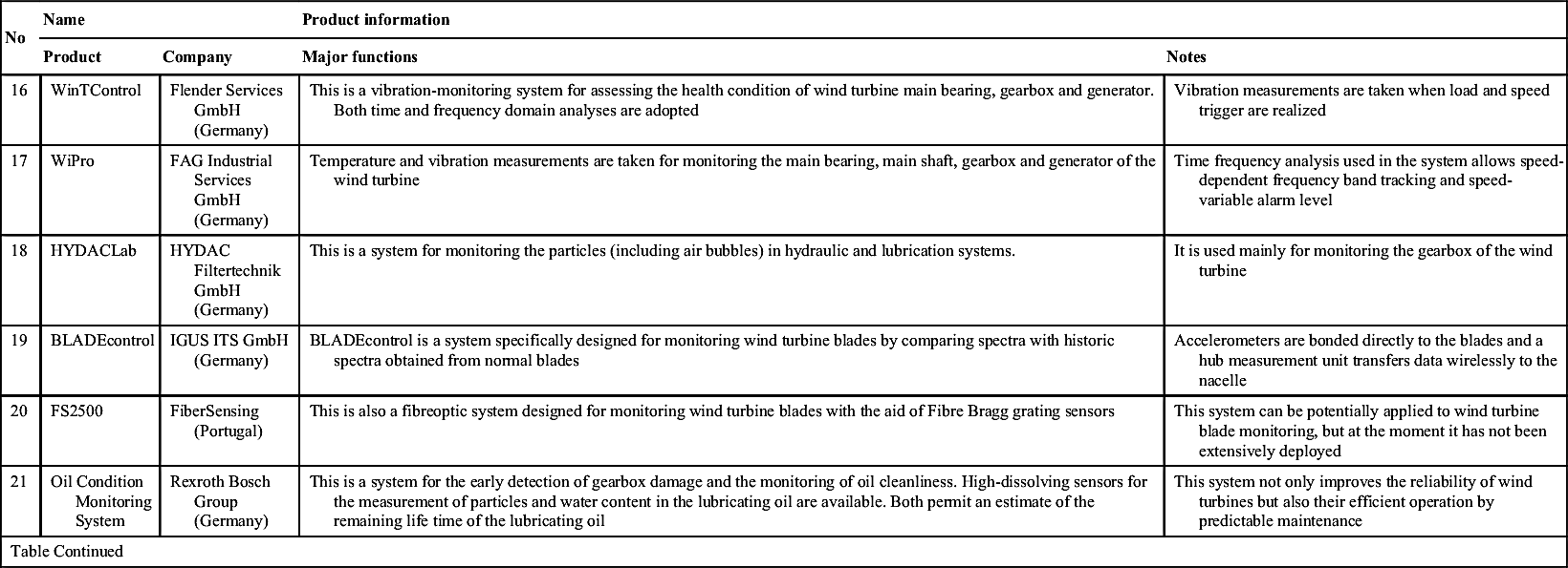
The application of a purpose-designed WT CMS has been strongly recommended by certification bodies, for example Germanischer LIoyd [41–43], following a series of catastrophic WT gearbox failures in the late 1990s. Today, a number of WT CMSs are commercially available to the wind industry [12]. Many of these were developed by experienced CM practitioners, such as SKF, Brüel & Kjær, GE Bently Nevada, Prüeftechnik and Gram & Juhl, based on the long-term experience of monitoring conventional rotating machines. Some of these commercial CMSs are listed in Table 18.2.
Table 18.2 shows that the majority of commercially available WT CMSs are vibration-analysis-based systems, although some are used in combination with oil particle counters and fibreoptic strain gauges to enhance their WT CM capabilities [44,45]. There are a few systems based on shaft torque or torsional vibration measurement and some use structural health monitoring [19,20]. It can also be seen that the available WT CMSs mainly focus on monitoring the WT drive train, i.e. the main bearing, shaft, gearbox and generator, using spectral analysis techniques. A few systems are specifically designed for WT gearbox lubrication oil or blade monitoring. This is because the WT drive train and blade components are expensive and their failure can cause long downtimes [14–16]. A typical vibration-analysis-based WT CMS is outlined in Fig. 18.4, where fibreoptic strain gauges and oil particle counters are optional. In principle, the application of this system will be helpful in reducing WT operational risk. However, to date no published work has demonstrated its effectiveness in improving WT availability and there have been false alarms and ineffective fault reports [12]. The high cost of WT CMSs and their interpretation complexity have discouraged WT operators from making wider use of them, despite the fact that they are fitted to the majority of large WTs (>1.5 MW) to ease certification. The unreliable CM results account for this embarrassed situation.
Different from traditional rotating machines, WTs often operate in remote locations, rotate at low and variable speed and work under constantly varying loads. As a consequence, WT CM signals, such as vibrations and temperatures, are dependent not only on component integrity, but also the operating conditions (eg rotational speed, loading and ambient temperature). In other words, WT component vibration and temperature changes do not necessarily indicate a fault occurrence, although the presence of a fault may lead to such changes. To demonstrate this, Fig. 18.5 shows the transverse vibration of a perfect shaft rotating at variable speed and subject to varying load, collected from a specially designed WT CM test rig, introduced in detail in [46,47].
From Fig. 18.5, it is seen that even without damage the shaft transverse vibration varies with WT load torque and rotational speed. Moreover, the larger the torque delivered, the stronger the vibration. Thus, shaft vibration is affected not only by machine dynamic integrity itself, but also by its operating conditions. Likewise, component temperatures, for example generator bearing or gearbox oil temperatures, also correlate with WT load and nacelle temperature. In order to demonstrate this, a practical CM dataset measured from an operational WT is shown in Fig. 18.6, where generator bearing temperature fluctuations clearly correspond to generator power fluctuations.
Table 18.2
| No | Name | Product information | ||
| Product | Company | Major functions | Notes | |
| 1 | WindCon3.0 | SKF (Sweden) | Collect, analyse and compile condition-monitoring data that can be configured to suit management, operators and maintenance engineers | The system focuses on the condition monitoring of wind turbine blades, main bearing, shaft, gearbox, generator and tower by the combined use of vibration transducers and a lube oil debris counter |
| 2 | TCM | Gram & Juhl (Denmark) | Advanced signal analyses on vibration, vibroacoustic and strain, combined with automation rules and algorithms for generating references and alarms | The WT blades, main bearing, shaft, gearbox, generator, nacelle and tower are monitored by using spectral analysis methods |
| 3 | WP4086 | Mita-Teknik (Denmark) | Integrated with WT SCADA, the system provides real-time frequency and time domain analyses of turbine operational signals and gives off alarms based on predefined thresholds | With the aid of eight accelerometers, the WT main bearing, gearbox and generator are monitored by using both time and frequency domain analysis techniques |
| 4 | Brüel & Kjær Vibro | Brüel & Kjær (Denmark) | Collect and process data at fixed intervals and remotely send results to diagnostic server. The time-waveform of the data at any time is accessible for further analysis | The WT main bearing, gearbox, generator, and nacelle (temperature and noise) are monitored by the approach of vibration analysis in combination with temperature and acoustic analyses |
| 5 | CBM | GE Bently Nevada (USA) | The system gives monitoring and diagnosis of drive-train parameters. Correlate CM signals with WT operational information (eg wind and shaft rotating speeds), and give off alarms via SCADA | The vibrations of WT main bearing, gearbox, generator and nacelle as well as bearing and oil temperatures are monitored |
| Table Continued | ||||

| No | Name | Product information | ||
| Product | Company | Major functions | Notes | |
| 6 | CMS | Nordex (Germany) | Actual vibration values during WT start-up period are compared with the reference values. Some Nordex turbines also use the Moog Insensys fibre optic measurement system | The system focuses on the monitoring of main bearing, gearbox and generator. The WT blades are also monitored if the WTs also install Insensys' fibreoptic system |
| 7 | SMP-8C | Gamesa Eolica (Spain) | Continuous online analysis of WT main shaft, gearbox and generator and compare their spectral trends. Warnings and alarms are given through wind farm management system | WT main shaft, gearbox and generator are online-monitored through the spectral analyses of their vibrations |
| 8 | PCM200 | Pall Europe Ltd (UK) | This is a real-time system for testing and assessing fluid cleanliness | The cleanliness of gearbox lubrication oil is monitored |
| 9 | TechAlert 10/20 | MACOM (UK) | TechAlert 10 is an inductive sensor to count and size the ferrous and non-ferrous debris, while TechAlert 20 is a sensor only for counting ferrous particles | Both systems are designed for monitoring the debris contained in lubrication or other circulating oils |
| 10 | Rotor Monitoring System (RMS) | Moog Insensys Ltd (UK) | RMS is in fact a blade-monitoring system, conducting the condition monitoring of wind turbine blades and rotor by measuring the strains in blade–root sections using fibreoptic technology | The load measurement by RMS is also helpful for the load control of pitch regulated wind turbines |
| 11 | MDSWind MDSWind-T | VULKΛN SEΛCOM (Germany) | MDSWind measures the vibrations of main bearing, gearbox, generator, and tower of the wind turbine, calculates and displays their statistic indices (eg RMS and Crest factor) online | MDSWind-T is a four-channel portable system developed based on MDSWind |
| Table Continued | ||||

| No | Name | Product information | ||
| Product | Company | Major functions | Notes | |
| 12 | Ascent | Commtest (New Zealand) | Ascent is a vibration analysis system for monitoring the main shaft, gearbox and generator of the turbine by the approach of spectral analyses and time domain statistics | System available in three complexity levels. Level 3 includes frequency band alarms, machine template creation, and statistical alarming |
| 13 | Condition Diagnostics System | Winergy (Germany) | The system analyses vibrations, load and oil to give diagnosis, predict and recommend for corrective action. Automatic fault identification is provided. Pitch, yaw and inverter monitoring can also be integrated into the system | It mainly focuses on the health monitoring of wind turbine main shaft, gearbox and generator through vibration analysis and oil debris counter |
| 14 | Condition Management System | Moventas (Finland) | This is a compact system initially designed for monitoring wind turbine gearbox by measuring temperature, vibration, load, pressure, speed, oil aging and oil particles | The system can be extended to monitor the generator and rotor as well as the controller of the wind turbine |
| 15 | OneProd Wind | Areva (France) | This system monitors the main bearing, gearbox and generator of the wind turbine by measuring oil debris, structure and shaft displacement, and electrical signals | It consists of operating condition channels to trigger data acquisitions, measurement channels for surveillance and diagnosis, optional additional channels for extended monitoring |
| Table Continued | ||||

| No | Name | Product information | ||
| Product | Company | Major functions | Notes | |
| 16 | WinTControl | Flender Services GmbH (Germany) | This is a vibration-monitoring system for assessing the health condition of wind turbine main bearing, gearbox and generator. Both time and frequency domain analyses are adopted | Vibration measurements are taken when load and speed trigger are realized |
| 17 | WiPro | FAG Industrial Services GmbH (Germany) | Temperature and vibration measurements are taken for monitoring the main bearing, main shaft, gearbox and generator of the wind turbine | Time frequency analysis used in the system allows speed-dependent frequency band tracking and speed-variable alarm level |
| 18 | HYDACLab | HYDAC Filtertechnik GmbH (Germany) | This is a system for monitoring the particles (including air bubbles) in hydraulic and lubrication systems. | It is used mainly for monitoring the gearbox of the wind turbine |
| 19 | BLADEcontrol | IGUS ITS GmbH (Germany) | BLADEcontrol is a system specifically designed for monitoring wind turbine blades by comparing spectra with historic spectra obtained from normal blades | Accelerometers are bonded directly to the blades and a hub measurement unit transfers data wirelessly to the nacelle |
| 20 | FS2500 | FiberSensing (Portugal) | This is also a fibreoptic system designed for monitoring wind turbine blades with the aid of Fibre Bragg grating sensors | This system can be potentially applied to wind turbine blade monitoring, but at the moment it has not been extensively deployed |
| 21 | Oil Condition Monitoring System | Rexroth Bosch Group (Germany) | This is a system for the early detection of gearbox damage and the monitoring of oil cleanliness. High-dissolving sensors for the measurement of particles and water content in the lubricating oil are available. Both permit an estimate of the remaining life time of the lubricating oil | This system not only improves the reliability of wind turbines but also their efficient operation by predictable maintenance |
| Table Continued | ||||
| No | Name | Product information | ||
| Product | Company | Major functions | Notes | |
| 22 | Gearbox Oil Condition Monitoring | Intertek (UK) | Intertek oil condition monitoring services include testing of gearbox oils and lubricants, helping clients extend runtimes for expensive turbines, windmills and other equipment, while minimizing downtime and costly repairs | This is an offline oil analysis system |
| 23 | Icount system and IcountPD Particle Detector | Parker (Finland) | Parker's system is an all-in-one system to determine whether or not system oil is contaminated and the best way to detect particles online or offline | IcountPD is a particle detector; while the Icount system provides early warning of any unwanted changes in hydraulic or lubrication oil quality. Thus increasing the availability of the machinery by reducing the need for unnecessary downtime |

Reproduced from W. Yang, P. Tavner, C. Crabtree, Y. Feng, Y. Qiu, Wind turbine condition monitoring: technical and commercial challenges, Wind Energy 17 (5) (2014) 673–693.


Thus, it is inferred that whilst a generator bearing fault leads to an increase in bearing temperature, the change of temperature is also correlated with the changes in ambient temperature and the power generated by the WT generator even if the generator cooling system is in good condition.
From the above discussion, one can conclude that vibration, temperature or other WT fault-related parameter responses are not solely dependent on WT integrity. In other words, changes in these fault-related parameters do not necessarily indicate the presence of a fault. In order to reduce false alarms, WT CMSs must carry out more detailed investigations than merely measuring amplitude to discern the true cause of variation, and triggering a fault alarm.
Additionally, the harsh operating environment exposes the WT to extreme temperatures, wind gusts and lightning strikes. As a consequence, WT electrical and power electronic systems are also prone to failure, see Fig. 18.7 [48] taken from the ReliaWind project, and their deterioration may be accelerated in worse offshore environments. Such failures could be repaired quickly onshore. But the strong wind speed offshore and access difficulties to offshore sites will exacerbate the effects of these failures and cause long downtimes. Existing WT CMSs have not fully considered the detection, diagnosis and prognosis of these failures.
The cost of a WT CMS is also an issue, since a large wind farm may require millions of pounds to equip the entire wind farm with such a WT CMS, excluding the fees for periodic recalibration. Additionally, the operator also faces the challenge of processing, transmitting, storing and interpreting the large amount of data generated by these systems.
Apart from this, the development of WT CMS is also limited by present IT technology. It is well known that both low- and high-speed rotating components are included in a WT. In theory, CM data from components with different rotational speeds should be collected by using different sampling frequencies to minimize the CM data size. For example, shaft vibration data are usually sampled at 2 kHz; gearbox and bearing vibration data at 20 kHz and so on. However, this is not normally realized in practice due to hardware limitations. To minimize data transmission, WT CMS processes WT data and transmits trends to the microprocessor continuously. Spectral analysis is conducted only when an unusual change is detected. Such a strategy mitigates the burden of data processing and transmission from offshore to onshore. However, it increases the risks of losing raw historical data once they are requested for detailed analysis.

Figure 18.7 Failure rate proportions attributable to geared-drive onshore WT subassemblies. Reproduced from M. Wilkinson, F. Spinato, Measuring & understanding wind turbine reliability, Proceeding of European Wind Energy Conference & Exhibition (EWEC) 2010, Warsaw, Poland, 20–23 April, 2010.
The last issue concerns WT CMS maintenance. In essence, a CMS consists of a number of electronic components and transducers, which are prone to failure in inclement offshore environments. Therefore, maintenance and recalibration of these electronic components and transducers should be conducted regularly as well to keep their good condition and correct performance. However, it is well known that the offshore WT maintenance window is very narrow. Maintenance activities can hardly cover the maintenance of CMS. Due to a lack of care, how to keep the CMS in good condition during its long service life is a challenging issue.
18.5. Signal processing techniques used for WT CM
The selection of appropriate signal processing and data analysis techniques is critical for the success of WT CM. If the fault-related characteristics can be correctly extracted using these techniques, fault growth can be assessed by observing characteristic variations and these characteristics are also important clues for fault diagnosis. To present a clear review the techniques that are already used by commercial WT CMSs and those that are still in research are discussed separately in the following.
18.5.1. Techniques adopted by commercial CMSs
Both time and frequency domain signal processing techniques have been adopted by commercial CMSs, for example the SKF WindCon3.0 shown in Fig. 18.8.
18.5.1.1. Time domain analysis
The SKF's WindCon system sets time domain warning and alarm levels and plots data trends against time, load or rotational speed, when a trend reaches a predefined threshold, the system triggers an alarm. Time domain trends are usually obtained from well-known parameters, such as overall vibration level, Crest factor, average vibration level and so on and the whole CM process is implemented online. However, CM results are inevitably influenced by varying load and environmental factors. The system also allows the user to review raw signal time waveforms and shaft vibration orbits. However, experience has shown that it is hard to assess WT's health condition by observing the signal waveforms alone, particularly when the turbine is working under varying load. In practice, some WT performance monitoring systems evaluate a WT's health status by comparing signals with neighbouring WTs [49], see Fig. 18.9.
From Fig. 18.9, it can be seen that an almost constant correlation is maintained when both monitored WTs are normal. Once the health condition of either one is changed, their relationship indicated by the correlation coefficient will fall apart. Such a technique is simple in calculation but its reliability will be affected by local terrain of the wind farm and wake effect.


18.5.1.2. Frequency domain analysis
Frequency domain techniques used in the WTCMS, for example envelope analysis [50,51], cepstrum analysis [52] and spectral Kurtosis [53], are based upon the fast Fourier transform (FFT). Considering the FFT was initially designed for processing linear stationary signals with constant amplitudes and fixed-frequency compositions, the maximum variations of the inspected WT CM signals need to be defined in advance, so that signal analysis accuracy can be guaranteed. Historic spectra can be traced with the aid of a waterfall diagram. However, as WTs rotate at variable speed and load, the waterfall diagram obtained is difficult to observe, even after calibration by the rotational speed. The WindCon system also provides a tool aiding the user to calculate the characteristic frequencies of the components at any rotational speed. The cursor function enables the user to select peaks, harmonics and sidebands in the spectrum. If adequate information about the machine or component is known, the type of fault can be readily judged with the aid of this tool. The signal processing techniques used in other WT CMSs are similar, although differences exist between different systems. For example, some WT CMSs use either FFT or cepstrum analyses; some, for example, the WP4086 developed by Mita-Teknik and the CBM by GE Bently Nevada, use acceleration envelope spectra; while some, for example the system developed by Brüel&Kjær, use both envelope and cepstrum analysis. Both envelope and cepstrum analyses are based upon the FFT and have been proved to be powerful in extracting faulty features from gearbox and bearing vibration signals. Although the FFT is widely used, it is not an ideal tool for processing WT CM signals which are nonlinear and non-stationary, due to varying speeds and loads and the negative influences of the environment on WT control. Therefore, more advanced signal processing techniques need to be investigated for WT CM.
18.5.2. Techniques in research
Today, a number of advanced signal processing techniques [54–66], including time-frequency analysis and neural network, are being researched to overcome the problems of conventional FFT-based techniques and to find a better solution for WT CM. To give an overview of these newly developed techniques, a brief review has been made and some are listed in Table 18.3 with the consideration of the following four aspects:
1. Advantages
2. Disadvantages
3. Online CM capability
4. Fault diagnosis capability.
Table 18.3
Technologies being researched for WT CM
| No | Technique | Advantages | Disadvantages | Online CM | Fault diagnosis |
| 1 | High-order spectrum | Able to detect the nonlinear relationships between different orders of the harmonics contained in the signal | It is still a tool for processing linear signals, not ideal for analysing WT CM signals | N | N |
| 2 | Continuous wavelet transform | Able to analyse non-stationary signals satisfactorily | It involves intensive calculations and is still a tool for processing linear signals. However, WT CM signals are often nonlinear | N | Y |
| 3 | Discrete wavelet transform | Able to analyse non-stationary signals efficiently | Unable to analyse nonlinear WT CM signals correctly, and unable to locate a desired frequency range flexibly | N | Y |
| 4 | Empirical mode decomposition | An ideal tool for processing non-stationary and nonlinear signals, like WT CM signals | Unable to locate a desired frequency range flexibly | N | Y |
| 5 | Energy tracking | An efficient tool for analysing WT CM signals | It inherits the disadvantages of wavelet transforms and the accuracy of its results is highly dependent on the correctness of WT speed | Y | Y |
| 6 | Wigner–Ville distribution | Able to analyse non-stationary signals satisfactorily | Unable to analyse nonlinear WT CM signals correctly | N | Y |
| 7 | Neural network | An ideal tool for developing real-time CMS. It takes all CM information into account, however it is able to process them efficiently | Difficult to train the neural network | Y | Y |
| 8 | Data-driven technique | Attributed to ‘natural’ decomposition of original signal and the use of phase information, it is ideal to detect incipient mechanical and electrical defects occurring in WTs | Complex computation and manual selection of interested intrinsic mode functions make it difficult to use online | N | Y |
| 9 | Genetic programming | Able to simulate complex problems mathematically | The physical mean of the obtained mathematical model is unknown | Y | Y |

Reproduced from W. Yang, P. Tavner, C. Crabtree, Y. Feng, Y. Qiu, Wind turbine condition monitoring: technical and commercial challenges, Wind Energy 17 (5) (2014) 673–693.
From Table 18.3 the following concerns arise:
1. Most of the techniques were only suitable for offline CM and fault diagnosis but were not ideal for online use because of the computational complexity;
2. Some newly developed techniques have not been fully demonstrated, although they may have been tested on one or two types of faults. The difficulties of gathering true WT conditions from overhauls and rebuilds and the fact that not all operational WTs have been monitored properly, means that at the moment it is a challenging task to test or prove these techniques;
18.6. Existing issues and future tendencies of WT CM
The CM of offshore WTs is reviewed in this chapter with the following conclusions:
1. SCADA-based and purpose-designed CMSs are currently available to modern offshore WTs with the following features:
a. The SCADA-based CMS requires additional cost. However, the low sampling frequency of SCADA data disables the system from carrying out detailed CM analysis, diagnosis and prognosis functions;
b. The purpose-designed CMS is an independent CM system consisting of data acquisition, data conditioning, data transmission modules and a number of transducers. Therefore, its hardware is expensive. But it collects CM data using high sampling frequency, which enables the detailed analysis, diagnosis and prognosis of key WT components;
c. More effort should be made to integrate these disparate monitoring methods.
2. Massive deployment of offshore WTs brings a pressing requirement for effective WT CM techniques, which should be:
a. Applicable to a wider range of WT concepts than hitherto;
b. Able to monitor the key components in the whole WT system rather than solely focussing on drive-train subassemblies;
c. Capable of detecting incipient defects and preventing secondary damage;
d. Capable of fault detection, diagnosis and prognosis;
e. Cost-effective in hardware and reliable in CM result.
3. In contrast to onshore WTs, offshore WTs are larger in size and moreover experience:
a. Stronger wind and harsher environment;
b. Longer repair and replacement downtimes due to accessing difficulties; and
c. Higher repair/replacement costs owing to the additional expenditure on special vessels and lifting facilities.
Therefore, offshore WT CM would play a more vital role in increasing economic return.
5. Further researches are required to tackle the following issues:
a. Process nonlinear, non-stationary CM signals quickly and accurately;
b. Successfully detect incipient WT faults under constantly varying operation conditions and improve the reliability of the CM result by overcoming the negative influences of external loads and other operational conditions;
c. Develop techniques dedicatedly to monitoring WT electrical and power electronic systems that contribute a large number of turbine failures. The faults of these systems are not an issue onshore due to the potential ease of repairs. However, they can result in long offshore downtimes due to site-accessing difficulties.
..................Content has been hidden....................
You can't read the all page of ebook, please click here login for view all page.